SPL Perfomer s800 User manual

2
Welcome
and thank you for choosing the Performer s.
The Performer s amplifier is an ultra-compact power amplifier that delivers x W to ohms loudspeak-
ers. In bridge mode it delivers W into ohms.
VOLTAiR technology is what we also call the SPL V Rail Technology within the Professional Fidelity series. This
makes the Performer s an outstandig device in terms of dynamic range, signal-to-noise ratio and headroom
delivering an exceptional sound experience with invincible serenity, transparency and realness.
Performer
s800
Stereo Power Amplifier
PWRPROTECT TEMP
VOLTAiR
120V DC Audi o Rail
Voltage Selection:
Fuse:
. Remove Fuse Holder
. Exchange Fuses
. Flip Over . Reinstall
AVIS: RISQUE DE CHOC ÉLECTRIQUE • NE PAS OUVRIR
RISK OF ELECTRIC SHOCK
DO NOT OPEN
CAUTION XLR WIRING
Pin = GND
Pin = Hot (+)
Pin = Cold (–)
Serial
Number
Made in Germany
Mono
,mm
Jack
INPUT L
INPUT L
AMP CTL
AMP CTL
Connect to SPL
Preamplier/DAC
AMP CTL output
for remote
power on/o.
INPUT R
INPUT R
-
.
-
-
.
-
-
.
-
-
.
-
-
.
-
-
.
T
R
I
M
T
H
R
U
T
H
R
U
I
N
P
U
T
I
N
P
U
T
-
.
-
-
.
-
-
.
-
-
.
-
-
.
-
-
.
T
R
I
M
V AC: T A L V
V AC: T A L V
Minimum Load: ΩMinimum Load: Ω
Minimum Load: Ω
~ V AC / ~V AC, Hz / Hz, P max. VA
+–
–
– +
BRIDGE
MODE
BRIDGE
MODE
NOTE: In Bridge Mode
INPUT R is NOT used!
In Bridge Mode
use INPUT L
ONLY.
NOTE: In Bridge Mode
L and R INPUT TRIMS
have to be set at the
same value!
+
BRIDGE MODE
ONOFF
Performer
s800
I
F
R

Content
Getting started
Front view
Rear view (Stereo Mode)
Rear view (Bridge Mode)
VOLTAiR – V Rail Technology
Comparisons
Inputs
Slave Thru
Trim
Bridge Mode
Speaker outputs
Bridge Mode
Protection circuits
DC Protection
Overheating protection circuit
AMP CTL (Amplifier Control)
Specifications
Line Inputs & Line Outputs
Speaker outputs
Output power
Output voltage
Output impedance
Damping factor
Frequency response
Signal-to-noise ratio
Gain
Total harmonic distortion
Internal Voltage
Power supply
Dimensions (incl. feet)
Weight
Important Notes
Declaration of CE Conformity
I
F
R

4
Getting started
Read thoroughly and follow the instructions as well as the security advices of the Quickstart
which is enclosed in the scope of delivery! You can also download the Quickstart here.
By pressing the -Button you get to the table of contents.
By pressing the -Button you get to the front view of the unit.
By pressing the -Button you get to the rear view of the unit.
By pressing the -Button you get to the previous content.
I
F
R
I
F
R

5
Front view
Performer
s800
Stereo Power Amplifier
PWRPROTECT TEMP
VOLTAiR
120V DC Audio Rail
Power LED 1
I
F
R
Protection LED 3
Temperature LED
2

6
Rear view (Stereo Mode)
Voltage Selection:
Fuse:
. Remove Fuse Holder
. Exchange Fuses
. Flip Over . Reinstall
AVIS: RISQUE DE CHOC ÉLECTRIQUE • NE PAS OUVRIR
RISK OF ELECTRIC SHOCK
DO NOT OPEN
CAUTION XLR WIRING
Pin = GND
Pin = Hot (+)
Pin = Cold (–)
Serial
Number
Made in Germany
Mono
,mm
Jack
INPUT L
INPUT L
AMP CTL
AMP CTL
Connect to SPL
Preamplier/DAC
AMP CTL output
for remote
power on/o.
INPUT R
INPUT R
-
.
-
-
.
-
-
.
-
-
.
-
-
.
-
-
.
T
R
I
M
T
H
R
U
T
H
R
U
I
N
P
U
T
I
N
P
U
T
-
.
-
-
.
-
-
.
-
-
.
-
-
.
-
-
.
T
R
I
M
V AC: T A L V
V AC: T A L V
Minimum Load: ΩMinimum Load: Ω
Minimum Load: Ω
~ V AC / ~V AC, Hz / Hz, P max. VA
+–
–
– +
BRIDGE
MODE
BRIDGE
MODE
NOTE: In Bridge Mode
INPUT R is NOT used!
In Bridge Mode
use INPUT L
ONLY.
NOTE: In Bridge Mode
L and R INPUT TRIMS
have to be set at the
same value!
+
BRIDGE MODE
ONOFF
Performer
s800
Stereo Mode
Stereo Mode
Stereo Mode
Stereo Mode
Stereo Mode
Stereo Mode
Stereo Mode
Stereo Mode
Mains Switch 5
Mains Voltage 4
I
F
R
Speaker Output L
11
Speaker Output R 15
AMP CTL 6
Input R 12
Input L
8
Slave Thru R 13
Slave Thru L
9
Input Trim R 14
Input Trim L
10

7
Rear view (Bridge Mode)
Bridge Mode
Bridge Mode
Voltage Selection:
Fuse:
. Remove Fuse Holder
. Exchange Fuses
. Flip Over . Reinstall
AVIS: RISQUE DE CHOC ÉLECTRIQUE • NE PAS OUVRIR
RISK OF ELECTRIC SHOCK
DO NOT OPEN
CAUTION XLR WIRING
Pin = GND
Pin = Hot (+)
Pin = Cold (–)
Serial
Number
Made in Germany
Mono
,mm
Jack
INPUT L
INPUT L
AMP CTL
AMP CTL
Connect to SPL
Preamplier/DAC
AMP CTL output
for remote
power on/o.
INPUT R
INPUT R
-
.
-
-
.
-
-
.
-
-
.
-
-
.
-
-
.
T
R
I
M
T
H
R
U
T
H
R
U
I
N
P
U
T
I
N
P
U
T
-
.
-
-
.
-
-
.
-
-
.
-
-
.
-
-
.
T
R
I
M
V AC: T A L V
V AC: T A L V
Minimum Load: ΩMinimum Load: Ω
Minimum Load: Ω
~ V AC / ~V AC, Hz / Hz, P max. VA
+–
–
– +
BRIDGE
MODE
BRIDGE
MODE
NOTE: In Bridge Mode
INPUT R is NOT used!
In Bridge Mode
use INPUT L
ONLY.
NOTE: In Bridge Mode
L and R INPUT TRIMS
have to be set at the
same value!
+
BRIDGE MODE
ONOFF
Performer
s800
Bridge Mode
Bridge Mode
Input
16
Slave Thru
17
I
F
R
Speaker Output +
18
Speaker Output – 19
Bridge Mode Switch 7

8
VOLTAiR – V Rail Technology
VOLTAiR is the synonym for our V Rail Technology within the Professional Fidelity series. The audio signals are
processed with an unequalled +/-V DC, which corresponds to twice that of discrete operational amplifiers and
four-times that of semiconductor operational amplifiers.
VOLTAiR Technology reaches outstanding technical and sonic performances. Technically especially in terms of
dynamic range and headroom and sonically especially in reproducing the finest details and delivering a totally
relaxed sounding audio experience. Music sounds absolutely natural.
I
F
R

9
Comparisons
These diagrams show how our VOLTAiR Technology compares to other circuits.
The direct relation between operating level and maximum level is fundamental for the classification: the higher
the operating level, the higher the maximum level a circuit can handle. And since virtually all essential acoustic
and musical parameters depend on this relation, a higher operating voltage also has a positive impact on the
dynamic range, distortion limit and signal-to-noise ratio.
0
20
40
60
80
100
120
Volt
30 V
120 V
+ / - Volt + / - Volt + / - Volt
Operating Voltage
120
125
130
135
140
145
dB
124,2
141,4
OPA @ V OPA @ V SPL- OP@ V
Dynamic Range
I
F
R

10
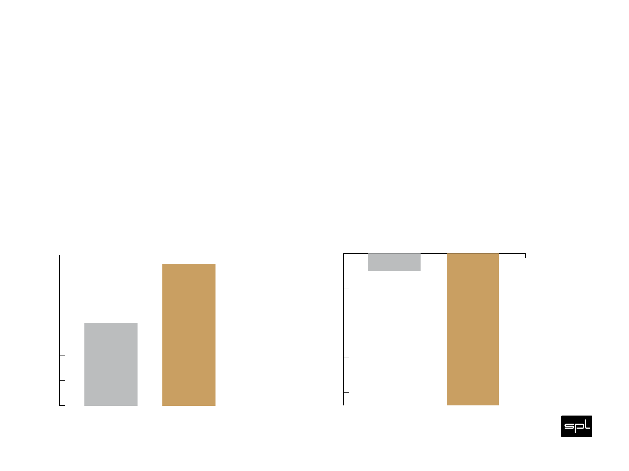
Do bear in mind that dB scales do not represent linear but rather exponential increases. A dB increase corre-
sponds to doubling the acoustic power, +dB correspond to twice the sound pressure level, and +dB corre-
spond to twice the perceived loudness.
When it comes to volume, the VOLTAiR Technology exhibits a performance, in regard to maximum level and dynamic
range, that is twice that of common components and circuits given that its values are approximately dB higher.
THD measurements show a difference of more than dB compared to the OPA at V — in terms of sound
pressure level, that corresponds to an improvement of more than %. The operating level most commonly used for
audio equipment is +/- volts.
Max. Audio Level
OPA @ V OPA @ V SPL-OP@ V
0
5
10
15
20
25
30
35
dBu
21,5
33,2
TL @ V OPA @ V SPL- OP@ V
-115
-113
-111
-109
-107
-105
dBu
-106
-114,2
THD&N
I
F
R

11
Inputs
The Performer s is equipped with XLR inputs (, ) for balanced connection to a pre-
amp. Full output power ( x W RMS into ohms or x W RMS into ohms) is per-
formed at + dBu at the input.
For unbalanced connection with e.g. RCA output connect Pin to Ground in the external
connector.
Voltage Selection:
Fuse:
. Remove Fuse Holder
. Exchange Fuses
. Flip Over . Reinstall
AVIS: RISQUE DE CHOC ÉLECTRIQUE • NE PAS OUVRIR
RISK OF ELECTRIC SHOCK
DO NOT OPEN
CAUTION XLR WIRING
Pin = GND
Pin = Hot (+)
Pin = Cold (–)
Serial
Number
Made in Germany
Mono
,mm
Jack
INPUT L
INPUT L
AMP CTL
AMP CTL
Connect to SPL
Preamplier/DAC
AMP CTL output
for remote
power on/o.
INPUT R
INPUT R
-
.
-
-
.
-
-
.
-
-
.
-
-
.
-
-
.
T
R
I
M
T
H
R
U
T
H
R
U
I
N
P
U
T
I
N
P
U
T
-
.
-
-
.
-
-
.
-
-
.
-
-
.
-
-
.
T
R
I
M
V AC: T A L V
V AC: T A L V
Minimum Load: ΩMinimum Load: Ω
Minimum Load: Ω
~ V AC / ~V AC, Hz / Hz, P max. VA
+–
–
– +
BRIDGE
MODE
BRIDGE
MODE
NOTE: In Bridge Mode
INPUT R is NOT used!
In Bridge Mode
use INPUT L
ONLY.
NOTE: In Bridge Mode
L and R INPUT TRIMS
have to be set at the
same value!
+
BRIDGE MODE
ONOFF
Performer
s800
balancedunbalanced
GND GND
1
2
3
1
2
3
cold –
hot + hot +
I
F
R

12
Slave Thru
The input is passively fed to the SLAVE THRU (, ) output for bi-wiring applications.
Trim
The input can be lowered with the TRIM switch (, ) from dB to -. dB in . dB
steps. This is helpful if you want to use multi speaker sets or speakers in a bi-wiring applica-
tion. It allows to level speakers with different efficiency to equal loudness.
Bridge Mode
In bridge mode only the left input is used. The right input and the trim switches are deactivated.
Voltage Selection:
Fuse:
. Remove Fuse Holder
. Exchange Fuses
. Flip Over . Reinstall
AVIS: RISQUE DE CHOC ÉLECTRIQUE • NE PAS OUVRIR
RISK OF ELECTRIC SHOCK
DO NOT OPEN
CAUTION XLR WIRING
Pin = GND
Pin = Hot (+)
Pin = Cold (–)
Serial
Number
Made in Germany
Mono
,mm
Jack
INPUT L
INPUT L
AMP CTL
AMP CTL
Connect to SPL
Preamplier/DAC
AMP CTL output
for remote
power on/o.
INPUT R
INPUT R
-
.
-
-
.
-
-
.
-
-
.
-
-
.
-
-
.
T
R
I
M
T
H
R
U
T
H
R
U
I
N
P
U
T
I
N
P
U
T
-
.
-
-
.
-
-
.
-
-
.
-
-
.
-
-
.
T
R
I
M
V AC: T A L V
V AC: T A L V
Minimum Load: ΩMinimum Load: Ω
Minimum Load: Ω
~ V AC / ~V AC, Hz / Hz, P max. VA
+–
–
– +
BRIDGE
MODE
BRIDGE
MODE
NOTE: In Bridge Mode
INPUT R is NOT used!
In Bridge Mode
use INPUT L
ONLY.
NOTE: In Bridge Mode
L and R INPUT TRIMS
have to be set at the
same value!
+
BRIDGE MODE
ONOFF
Performer
s800
I
F
R

13
Speaker outputs
You can connect or ohms loudspeakers to the speaker outputs
(, ) in stereo mode. In bridge mode you can connect ohms
loudspeakers to the speaker outputs. You can either use the ø mm
cable hole (screwable) or the banana plugs of the gold-plated loud-
speaker binding posts.
Make sure that you do not mix up the polarity of the speaker connec-
tions and that the power amplifier is switched off when you connect
speaker cables.
Voltage Selection:
Fuse:
. Remove Fuse Holder
. Exchange Fuses
. Flip Over . Reinstall
AVIS: RISQUE DE CHOC ÉLECTRIQUE • NE PAS OUVRIR
RISK OF ELECTRIC SHOCK
DO NOT OPEN
CAUTION XLR WIRING
Pin = GND
Pin = Hot (+)
Pin = Cold (–)
Serial
Number
Made in Germany
Mono
,mm
Jack
INPUT L
INPUT L
AMP CTL
AMP CTL
Connect to SPL
Preamplier/DAC
AMP CTL output
for remote
power on/o.
INPUT R
INPUT R
-
.
-
-
.
-
-
.
-
-
.
-
-
.
-
-
.
T
R
I
M
T
H
R
U
T
H
R
U
I
N
P
U
T
I
N
P
U
T
-
.
-
-
.
-
-
.
-
-
.
-
-
.
-
-
.
T
R
I
M
V AC: T A L V
V AC: T A L V
Minimum Load: Ω
Minimum Load: Ω
Minimum Load: Ω
~ V AC / ~V AC, Hz / Hz, P max. VA
+–
–
– +
BRIDGE
MODE
BRIDGE
MODE
NOTE: In Bridge Mode
INPUT R is NOT used!
In Bridge Mode
use INPUT L
ONLY.
NOTE: In Bridge Mode
L and R INPUT TRIMS
have to be set at the
same value!
+
BRIDGE MODE
ONOFF
Performer
s800
I
F
R

14
Bridge Mode
The Performer s can be operated in bridge mode to combine both channel amps for maximum power ( W
RMS into at least ohms). Only use the left input then.
• Set the BRIDGE MODE () switch to ON.
Warning: Power down the Performer s with the mains switch () before
you activate the BRIDGE MODE switch.
In bridge mode you only connect a single loudspeaker with at least ohms to the Performer s power ampli-
fier. Use the positive binding post (+) of the left speaker output to connect to the positive (+) input of the speaker.
Use the positive binding post (+) of the right speaker output to connect to the negative (–) input of the speaker.
In bridge mode both the Trim switch and the right input are deactivated.
Voltage Selection:
Fuse:
. Remove Fuse Holder
. Exchange Fuses
. Flip Over . Reinstall
AVIS: RISQUE DE CHOC ÉLECTRIQUE • NE PAS OUVRIR
RISK OF ELECTRIC SHOCK
DO NOT OPEN
CAUTION XLR WIRING
Pin = GND
Pin = Hot (+)
Pin = Cold (–)
Serial
Number
Made in Germany
Mono
,mm
Jack
INPUT L
INPUT L
AMP CTL
AMP CTL
Connect to SPL
Preamplier/DAC
AMP CTL output
for remote
power on/o.
INPUT R
INPUT R
-
.
-
-
.
-
-
.
-
-
.
-
-
.
-
-
.
T
R
I
M
T
H
R
U
T
H
R
U
I
N
P
U
T
I
N
P
U
T
-
.
-
-
.
-
-
.
-
-
.
-
-
.
-
-
.
T
R
I
M
V AC: T A L V
V AC: T A L V
Minimum Load: ΩMinimum Load: Ω
Minimum Load: Ω
~ V AC / ~V AC, Hz / Hz, P max. VA
+–
–
– +
BRIDGE
MODE
BRIDGE
MODE
NOTE: In Bridge Mode
INPUT R is NOT used!
In Bridge Mode
use INPUT L
ONLY.
NOTE: In Bridge Mode
L and R INPUT TRIMS
have to be set at the
same value!
+
BRIDGE MODE
ONOFF
Performer
s800
Voltage Selection:
Fuse:
1. Remove Fuse Holder
2. Exchange Fuses
3. Flip Over 4. Reinstall
AVIS: RISQUE DE CHOC ÉLECTRIQUE • NE PAS OUVRIR
RISK OF ELECTRIC SHOCK
DO NOT OPEN
CAUTION
XLR WIRING
Pin 1 = GND
Pin 2 = Hot (+)
Pin 3 = Cold (–)
Serial
Number
Made in Germany
Mono
3,5mm
Jack
INPUT L
INPUT L
AMP CTL
AMP CTL
Connect to SPL
Preamplier/DAC
AMP CTL output
for remote
power on/o.
INPUT R
INPUT R
0
-
5
.
5
-
5
-
4
.
5
-
4
-
3
.
5
-
3
-
2
.
5
-
2
-
1
.
5
-
1
-
0
.
5
T
R
I
M
T
H
R
U
T
H
R
U
I
N
P
U
T
I
N
P
U
T
0
-
5
.
5
-
5
-
4
.
5
-
4
-
3
.
5
-
3
-
2
.
5
-
2
-
1
.
5
-
1
-
0
.
5
T
R
I
M
230V AC: T 4 A L 250 V
115V AC: T 8 A L 250 V
Minimum Load: 4Ω
Minimum Load: 4Ω
Minimum Load: 8Ω
~ 115V AC / ~230V AC, 50 Hz / 60 Hz, P max. 855VA
+
–
–
–
+
BRIDGE
MODE
BRIDGE
MODE
NOTE: In Bridge Mode
INPUT R is NOT used!
In Bridge Mode
use INPUT L
ONLY.
NOTE: In Bridge Mode
L and R INPUT TRIMS
have to be set at the
same value!
+
BRIDGE MODE
ON
OFF
Performer
s800
I
F
R

15
Protection circuits
The Performer s has protection circuits against DC (direct current) voltage at the output and against
overheating.
DC Protection
If DC is detected at the outputs, the Performer s automatically switches off. DC voltage can be an indication
for a defective power stage. The PROTECT LED () on the front indicates that the protection circuit is activated and
the power stage has been switched off.
The Performer s does not automatically switch on again. It needs to be switched off manually with the mains
switch (). Wait at least one minute before switching the Performer s on again.
If the Performer s repetitively switches off due to a DC detection please contact your dealer.
Overheating protection circuit
At about ° C at the heat sink, the Performer s will switch off. After the temperature has fallen below ° C,
the amplifier automatically switches on again. The TEMP LED () on the front indicates the overheating.
I
F
R

16
AMP CTL (Amplier Control)
If you use the Performer s via AMP CTL with a SPL Phonitor x or SPL Director as a pre-
amp, the Performer s can be switched between standby and operation together with the
Phonitorx or the Director. Therefore you only have to connect the AMP CTL jacks () with a
,mm mono mini jack cable.
Warning: Use only SPL Phonitor x or SPL Director for amplifier control.
Never connect other devices to the AMP CTL jack.
Voltage Selection:
Fuse:
. Remove Fuse Holder
. Exchange Fuses
. Flip Over . Reinstall
AVIS: RISQUE DE CHOC ÉLECTRIQUE • NE PAS OUVRIR
RISK OF ELECTRIC SHOCK
DO NOT OPEN
CAUTION XLR WIRING
Pin = GND
Pin = Hot (+)
Pin = Cold (–)
Serial
Number
Made in Germany
Mono
,mm
Jack
INPUT L
INPUT L
AMP CTL
AMP CTL
Connect to SPL
Preamplier/DAC
AMP CTL output
for remote
power on/o.
INPUT R
INPUT R
-
.
-
-
.
-
-
.
-
-
.
-
-
.
-
-
.
T
R
I
M
T
H
R
U
T
H
R
U
I
N
P
U
T
I
N
P
U
T
-
.
-
-
.
-
-
.
-
-
.
-
-
.
-
-
.
T
R
I
M
V AC: T A L V
V AC: T A L V
Minimum Load: ΩMinimum Load: Ω
Minimum Load: Ω
~ V AC / ~V AC, Hz / Hz, P max. VA
+–
–
– +
BRIDGE
MODE
BRIDGE
MODE
NOTE: In Bridge Mode
INPUT R is NOT used!
In Bridge Mode
use INPUT L
ONLY.
NOTE: In Bridge Mode
L and R INPUT TRIMS
have to be set at the
same value!
+
BRIDGE MODE
ONOFF
Performer
s800
I
F
R

17
Specications
Line Inputs & Line Outputs
• Neutrik XLR, balanced, Pin = (+)
• Input impedance: kohms
• Input trimming: dB to -. dB in . dB steps
• Input sensitivity: + dBu
• Output impedance (Slave Thru) is defined by the connected device
• Crosstalk: - dB (@ kHz)
Speaker outputs
• pairs binding posts with ø mm cable hole (screwable) and banana plug; fully encapsulated
Output power
• x W RMS into Ohm
• x W RMS into Ohm
• x W RMS into at least Ohm in bridge mode
I
F
R

18
Output voltage
• V Peak-to-Peak (stereo)
• V Peak-to-Peak (bridge)
• V RMS (stereo)
• V RMS (bridge)
Output impedance
• < ., Hz to kHz (stereo)
• < ,, Hz to kHz (bridge)
Damping factor
• > , Hz to kHz, at ohms (stereo)
• > , Hz to kHz, at ohms (bridge)
Frequency response
• Hz to kHz +, –, dB
• < Hz to kHz +, – dB
I
F
R

19
Signal-to-noise ratio
• > dB (wide-band, unweighted, referred to full power output)
• > dB (A-weighted)
Gain
• dB (stereo)
• dB (bridge)
Total harmonic distortion
• < ,% at kHz, at W, ohms
• < ,% at kHz at W, ohms
I
F
R

20
Internal Voltage
• +/- V
Power supply
• Mains voltage: V AC / Hz; V AC / Hz
• Fuses: V: T A; V: T A
• Power consumption: max VA
• Idle power consumption: W
• Standby power consumption: . W
Dimensions (incl. feet)
• (WxHxD) . x . x in ( x x mm)
Weight
• . lbs (. kg), unit only
• . lbs (. kg), shipping
I
F
R
Table of contents
Other SPL Amplifier manuals

SPL
SPL Phonitor se User manual

SPL
SPL Crescendo duo User manual

SPL
SPL Auditor 2910 User manual

SPL
SPL Phonos User manual

SPL
SPL Channel One Mk3 User manual

SPL
SPL Channel One 2950 User manual

SPL
SPL Phonitor xe User manual

SPL
SPL Phonitor 2 User manual

SPL
SPL Director User manual

SPL
SPL Professional Fidelity Series User manual

SPL
SPL Phonitor e User manual

SPL
SPL performer s800 User manual

SPL
SPL Phonitor x User manual

SPL
SPL Director Mk2 User manual

SPL
SPL Phonitor 3 DAC User manual

SPL
SPL Professional Fidelity Phonitor x User manual

SPL
SPL Reducer 1160 User manual

SPL
SPL Cabulator 2930 User manual

SPL
SPL Professional Fidelity Series User manual

SPL
SPL 9945 User manual