4
The DMC dual-channel mastering console completes the range of SPL 120 V
mastering consoles. Housed in a 19”/5U rack mount chassis the DMC features
the same unique 120 volts rails like the MMC 1 and MMC 2 multi-channel
consoles to achieve the optimum audio performance.
The purpose of the development was the creation of mastering consoles
that would be superior in audio quality to all known and foreseeable audio
formats, whether analog or digital. Such consoles would provide both for
an unaltered reproduction of the sonic quality of SACD and in the process,
remain a safe capital investment for many years.
The DMC is conceived as the center of a mastering environment to provide
speaker management, sources and returns connectivity, input and output
trimming, pure analog 2-channel master fader and monitor level setting. As
an option, the DMC can be supplemented with the SPL MasterBay to provide
an automated 8 x 2 channel insert routing of external processors.
Digital audio formats have undergone continuous development and change
and will continue to do so. The degree of incompatibility created by the
“format war” between PCM and DSD has persuaded us to opt for a technology
that is superior in dynamic range, headroom and sound quality to either or
any other such format – and constitutes discrete analog technology in its
most advanced implementation. Moreover additional prerequisites speak for
the employment of high-performance analog technology:
ThenumberofnecessaryAD/DA conversions should be reduced to a minimum.
With the DMC, digital sources can be connected to a digital router, which
outputs the selected source through the preferred DA converter. This ensures
that the sound quality remains comparable and is not affected by converter
differences.
From a purely aesthetic standpoint, high quality analog outboard processing
consistently proves itself superior to digital processing. The analog concept
allows for problem-free integration of such analog processors.
Monitors and power amplifiers are almost exclusively analog in design. Yet
another converter at this point in the chain only degrades monitoring signal
paths. Furthermore DSD signals cannot be monitored on a digital monitoring
that operates in PCM.
Technolog y
SPL’s new SUPRA operation amplifiers are used throughout the DMC’s design.
They perform at an industry benchmark 120 volts and were developed during
a four-year period during which SPL searched for a new generation of superior
discrete analog op amps. The SUPRA op amp achieves a signal-to-noise ratio
of 116dB with a headroom of 34dB. The dynamic range amounts to 150dB
with a frequency bandwidth of 200kHz.
Withsuchspecifications,theDMC ridescomfortablybeyondtherequire-
ments of either the current maximum 24 bit and 192kHz PCM format or 1 bit
and 256 fs DSD format. It is simply not realistic to expect at any foreseeable
future date a digital technology environment in which the DMC could become
a “bottle neck”.
Fade In
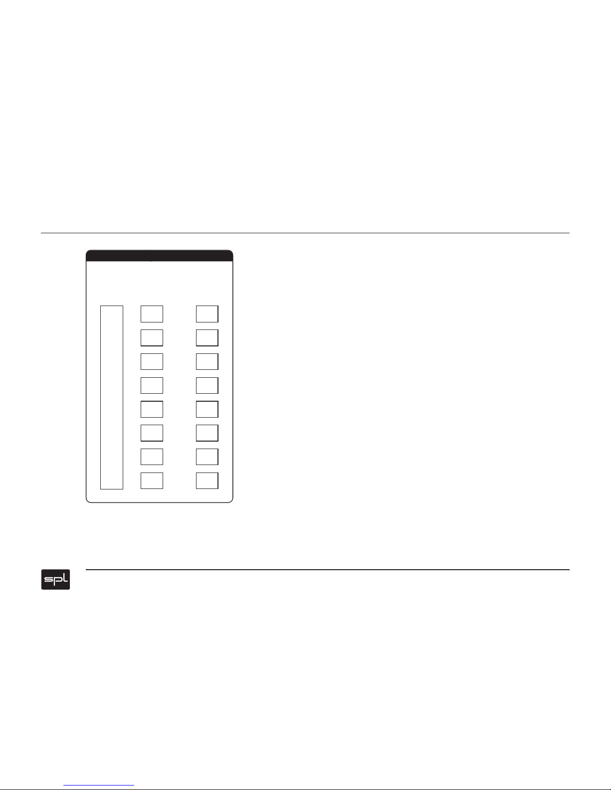
Master Fader
-
8
0
-
5
5
-
4
4
-
4
0
-
3
4
-
3
2
-
2
9
-
2
5
-
2
3
-
2
1
-
1
9
-
1
7
-
1
5
-
1
3
-
1
1
-
9
-
7
-
5
-
3
-
1
0
dB