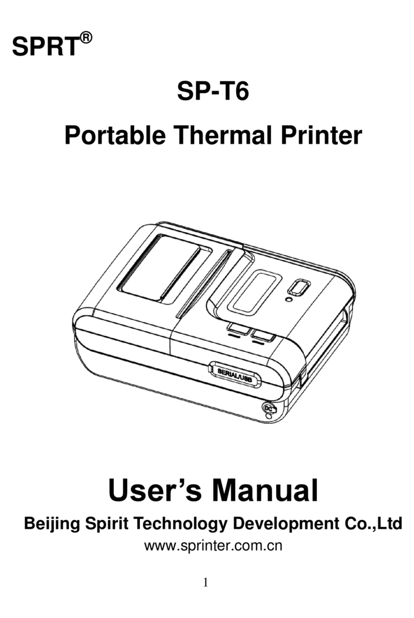
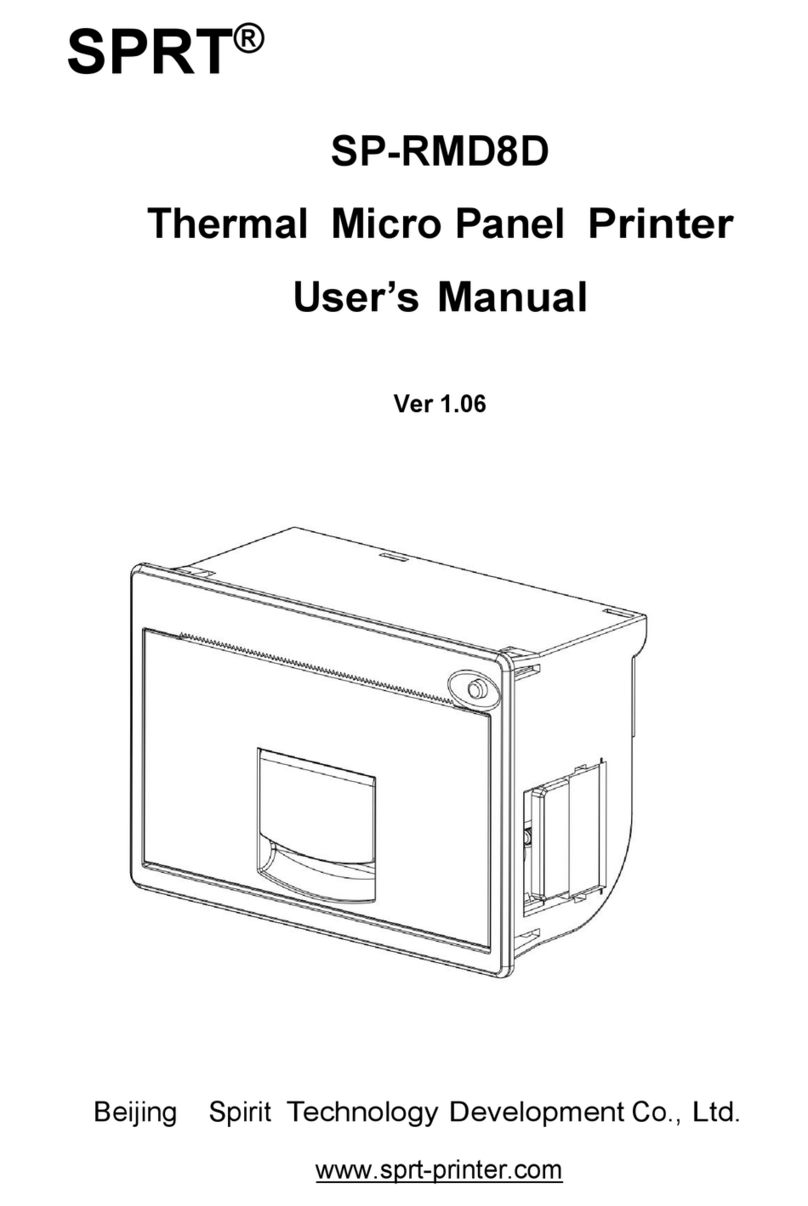
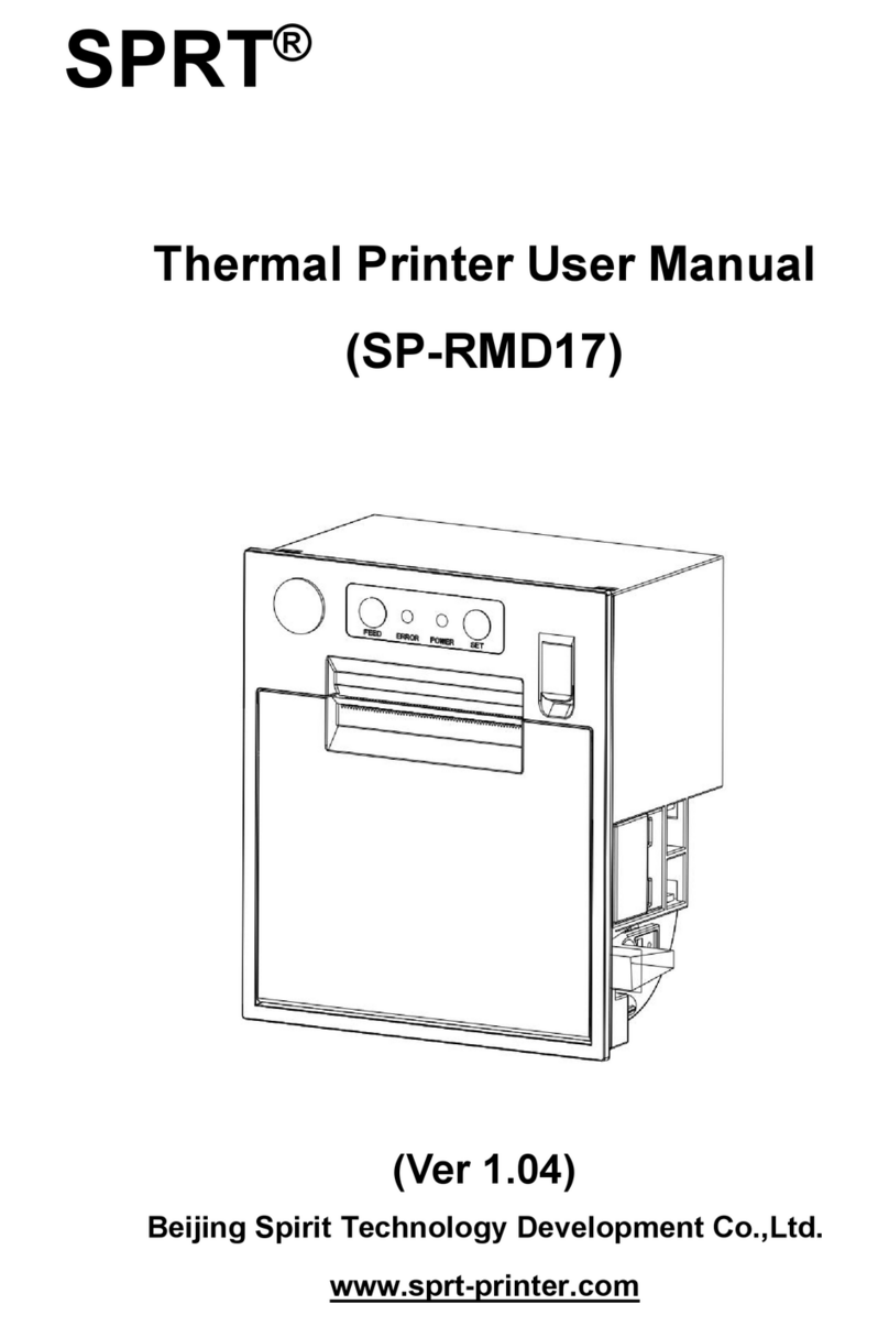
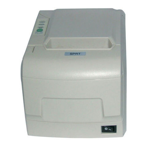
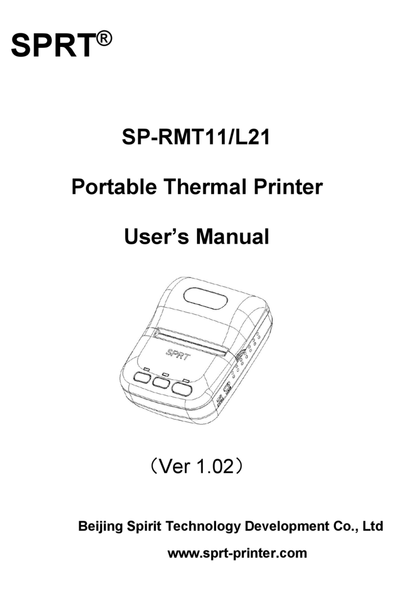
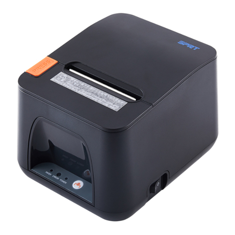
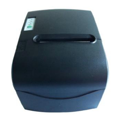
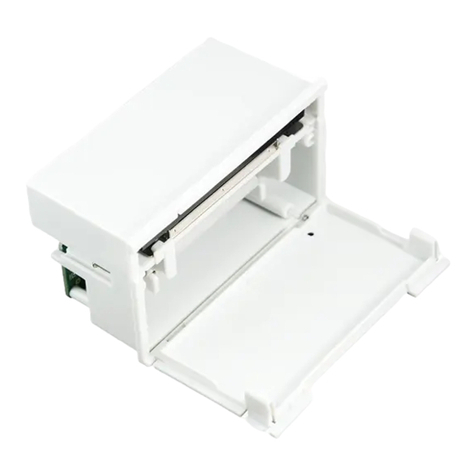
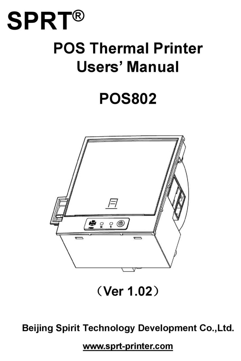
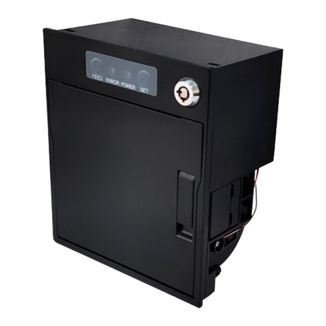
SPRT SP Series User manual

1
SPRT
®
Micro Dot Matrix Printers
User’s Manual
V1.1
Beijing Spirit Technology Development Co, Ltd.
Before using this product please read the manual and keep it for
later use
2010.6

2
File version description
Date Version Amended content
2008 V1.0 /
2010 V1.1 Add content of DVII series

3
Content
Content ............................................................................................................................................. 3
Product brief..................................................................................................................................... 5
Chapter 1 Feature and Performance .............................................................................................. 6
1.1 Features .............................................................................................................................. 6
1.2 Performance Index.............................................................................................................. 6
Chapter 2 System Installation.................................................................................................... 8
2.1 Installation Dimension........................................................................................................ 8
A model diagram2-1 ...................................................................................................... 8
T model diagram 2-2...................................................................................................... 9
C model diagram 2-3 ..................................................................................................... 9
DN model diagram 2-4 ................................................................................................ 10
DⅦmodel diagram 2-5 ................................................................................................ 10
2.2 Paper Roll Installation .......................................................................................................11
A series:........................................................................................................................11
DⅦ series:................................................................................................................... 14
2.3 Power Supply Connection ................................................................................................ 16
Chapter 3 Operation ................................................................................................................ 17
3.1 Serial Interface Connection .............................................................................................. 17
3.1.1 CFseries interface pinsdefinition ........................................................................ 18
3.1.2 DⅦseriesinterface pins definition ...................................................................... 18
3.1.3 Other series(except CF、DⅦ)interface pins definition................................ 19
3.1.4 CF and TF series setup ....................................................................................... 19
3.1.5 DⅦ series setup.................................................................................................. 20
3.1.6 Other series(except CF、TF and DⅦ)setup ............................................... 21
3.2 Parallel connection ........................................................................................................... 23
3.3 Buttons and Indicators...................................................................................................... 24
3.4 self-test ............................................................................................................................. 25
3.5 printer Initialization.......................................................................................................... 25
Chapter 4 Print Commands· ........................................................................................................ 26
4.1 Summary .......................................................................................................................... 26
4.2 Command details.............................................................................................................. 26
4.2.1 Paper Feed Commands .......................................................................................... 26
4.2.2 Format Setting Commands .................................................................................... 27
4.2.3 Character Setting Commands ................................................................................ 33
4.2.4 User-defined Character Setting Commands .......................................................... 37
4.2.5 Graphics Print Commands..................................................................................... 39
4.2.6 Initialization Command ......................................................................................... 40
4.2.7 Data Control Commands ....................................................................................... 40
4.2.8 Chinese Print Control Commands· ........................................................................ 42
4.3 Printer default parameter setting commands .................................................................... 45
4.3.1 Enter、Exit setting mode ...................................................................................... 46
4.3.2 printer basic parameter setting............................................................................... 46
Chapter 5 Printer Model Alteration and Protection..................................................................... 48
4
5.1 Print Head Protection ....................................................................................................... 48
5.2 Other................................................................................................................................. 48
Chapter 6 Printer Using under Windows........................................................................................ 48
Appendix 1 Effective code table ................................................................................................. 49
Appendix 2 Printing commands table ......................................................................................... 51

5
Introd ction
SP series dot panel printer is dot matrix smart printer developed by Beijing Spirit
Technology Development Co Ltd facing the 21st century.Machine itself uses the new import core
comes with single - chip computer small volume、light weight、fully featured、high-speed、high
definition、good appearance、easy operation and easy connection .etc.SP series dot matrix printers
have complete models standard installation dimension is the ideal matching product for updating
by Medical equipment、fire control、industry control and other instruments.
SP micro dot matrix printers not only can print ASCII characters but also can print English
Greek German French Russian Japanese katakana and GB Chinese character library level
I II a large number of mathematics symbols
special-purpose symbols and
various kinds of graphic and curving symbols. May by commands replace the printed word
line spacing and character size self-define partial code character and self-test.
SP micro dot matrix printers have windows driver can print various characters、chinese and
figures directly under WINDOWS of PC.

6
Chapter 1 Feat re and Performance
1.1 Feat res
◇
Adopt impact dot-matrix print method.
◇
Special design for available being installed on the vertical panel of the instrument or
equipment conveniently.
◇Comes with single - chip processor have standard parallel or serial could online use with
various microcomputers or smart instruments conveniently.
◇Real time commands to print chinese、character、figure and others also can print standard
6×7ASCIIcharacter and 16×16、12×12 chinese.Command set could
compatible with traditional
printer.
◇Speed have 1.2line/s、0.7line/s、0.4 line/s、2.5 line/s、1.5 line/s by model.
◇Self-test print full codes character has high definition and elegant fonts.
◇ Power DC 5V±5% 1.5A
◇Operation temp 0~50℃
◇Can work under DOS and Windows interface.
1.2 Performance Index
◇Print Method: impact dot-matrix
◇ Print paper: plain white paper width: 44.5±0.5mm or 57.5±0.5mm
Inner diameter: 40mm (max.)
Outer diameter: 80mm (max.)
◇GB level I II Chinese fonts library.
◇ Enough buffer 32K
◇Print font: total 448 characters including 96 ASCII characters Greek
German French letters Russian Japanese katakana and partial Chinese
characters, mathematics symbols, print symbols and graphic symbols
◇Character structure: ANK: 6×7 dots、Chinese: 8×16 or 6×12
Chinese character: 16×16/12×12
◇Graphic symbols: 6×8 dots

7
◇Interface: parallel interface (compatible with CENTRONICS) or serial
interface (compatible with RS-232C or TTL).
◇Interface connector: parallel port: 26-pin flat cable socket (T is DB25 orifice); serial
port: 10-pin flat cable socket or 5-pin single-row socket(T is DB25 needle);
◇ Control code: ESC、FS control codes
◇ Reliability:MCBF (Average lines of none error)Reliability: MCBF:(5~15)× 106
◇ Power:DC5V±5% 1.5A
◇ Operation temp:0~50℃relative temp:10~80%
◇ Installation dimension details see the chapter 2
The Main Characteristics of SP Series Printers
Model Character/line
(5×7)
Character
dimension(mm)
Dots/line
Speed(line/s)
16Series 16 1.8×2.5(W×H) 96 1.2
24 Series
24 1.7×2.4(W×H) 144 0.7
40Series 40 1.1×2.4(W×H) 240 0.4
24F Series
24 1.7×2.6(W×H) 144 2.5
40F Series
40 1.1×2.6(W×H) 240 1.5

8
Chapter 2 System Installation
2.1 Installation Size
The printer’s outline dimension is as Fig. 2-1 shows:
A
1
10
56+0.2
+0.1
103+0.2
+0.1
开口尺寸
103
108.5
56
61.89
62.3
Fig re2-
--
-1

9
T
40.3
159
106
Fig re2-
--
-2
C
108.2+0.2
+0.1
114+0.2
+0.1
开口尺寸
114
62.9
108.2
4-?3.5
122.4
106.7
128.6
121.8
Fig re 2-
--
-3

10
DN
57+0.2
+0.1
103.1+0.2
+0.1
开口尺寸
61.2
105.2
57
103.1
Fig re 2-
--
-4
DⅦ
ⅦⅦ
Ⅶ
Fig re 2-
--
-5

11
2.2 Paper Roll Installation
SP series dot matrix printer uses 44.5mm/57.5mm paper roll the paper has already been installed
at ex-factory for SP micro dot matrix printers but the paper head has not been inserted in the print
head this is in order to prevent the print head from damage while transporting the printer for
long-distance or storing it for a long time so must insert the head of the paper roll in the print
head firstly before using the printer. The general steps of installing the paper for SP series printers
are as follows:
A:
::
:
(1)Take down the front cover of the printer as Fig. 2-6 shows;
Fig re 2-
--
-6
(2)Take down the whole printer from the instrument panel please according to Fig. 2-7 shows:
clamp the two sides movable handle of the printer with fingers take down the whole printer from
the instrument panel please confirm the power of the printer has already been turned off before
taking down the printer ;

12
Fig re 2-
--
-7
(3)Take down the paper roller from the printer (see Fig.2-8) if there is already paper in the
printer can jump over this step to the fifth step;
Fig re 2-
--
-8
(4)Put the new paper on the paper roller and install the roller firmly according to Fig.2-9

13
shows so that it won’t lose out.
Fig re 2-
--
-9
(5)Cut the paper end like Fig.2-10

14
Fig re 2-
--
-10
(6)Put through the power of printer press SEL button make SEL indicator
to put out then press LF button make the print head to turn and insert the end of paper into the
paper-in slot by hand and make sure that the paper end appears from above the print head the
paper should appear for a certain length press LF button or SEL button again. Turn off the
power and close the front cover pull the paper end out through the paper-out slot in the front
cover.
(7)Install the whole printer to the instrument panel according to following Fig.
C DN series is opening front panel and press feed.
T series is opening front cover first press ESL button then feed button.
Notice:pls not use hand to pull paper forward or back
DⅦ
ⅦⅦ
Ⅶ:
::
:
(1) As figure 2-11:
Push panel center inward then inner shell will auto eject when released.
(2)After inner shell ejected hold both sides and pull them outward until the end as
direction of figure 2-12 rotate it upward and press the whole downward until fastened.
Fig re2-
--
-11

15
(3)Install paper roll to paper reel as figure 2-13 hold both sides of paper reel put paper roll
into paper case then release paper reel and fastened it.
(4)Switch on press feed button and insert paper from feeding paper slot press feed button
again to stop feeding after paper comes out. As figure2-14:
Fig re 2-12
Fig re- 13

16
(5)Hold two sides of inner shell rotate inner shell downward and push it inward as the
same time.
(6)
P sh inner shell f lly,fastened with o ter,paper installation is over.As fig re 2-16:
::
:
Notice:
::
:
1、 The fluffy paper roll will not be pushed easily and happen paper jam hold the paper
tightly and push it inward as the direction of figure 2-17 until inner shell is inserted
Fig re2-
--
-14
Fig re 2-
--
-15
Fig re 2-
--
-16

17
fully.
2、When fail to push inner shell inward pls pull out then push again not use too big
strength or the printer will be damaged.
2.3 Power S pply Connection
Dot matrix printer use +5V DC power.
SP micro dot matrix printers adopt single DC+5V power supply.
A two-line power cable with plug has been offered. The plug has polarity protection mechanisms
can be inserted directly in the socket which is on the control panel of SP micro dot matrix printers.
The red line of the power cable should be connected to the positive pole (+) of power the white
line should be connected to the negative pole (–) of power. Please note that the polarity of the
power shouldn't be connected incorrectly the voltage of the power must be in the permitting range
otherwise will cause permanent damage to the printer.
Chapter 3 Printer Operation
3.1 Serial Interface Connection
The serial interface of SP micro dot matrix printers is compatible with RS-232C standard or TTL
support RTS/CTS and XON/XOFF protocols the interface sockets are IDC10 needle socket、DB25
hole socket、 5-pin single row socket. The pin order of serial port is as Fig. 3-1 shows:
IDC10 needle socket No. as figure 3-1
Fig re 2-
--
-17

18
1 9
21 0
Fig re 3-
--
-1 Pin order of IDC10 needle serial interface
DB25 hole serial interface socket No. as figure 3-2
Fig re 3-
--
-2 DB25 hole serial interface socket No.
5PIN single row serial interface socket No. as figure3-3
Fig re3-3 5PIN single row serial interface socket No.
3.1.1 Pin assignment of CF series interface
CF series interface use IDC-10 socket pin assignment as figure3-4
Signal Pin No. source Instruction
RXD 3 Host Printer receives data from host
TXD 5 Printer Printer transmits control code X-ON/X-OFF and
data to host when using X-ON/X-OFF handshaking
protocol
CTS 4 Printer Signal “MARK” indicates that the printer is “BUSY” and
unable to receive data; “SPACE” indicates that the printer
is “READY” for receiving data
GND 9 - Signal Ground
Figure 3-4 Pin assignment of CF series serial interface socket

19
3.1.2 Pin assignment of DⅦ
ⅦⅦ
Ⅶ series interface
DⅦ series serial sockets have COM1 and COM2 both use IDC-10 their function are the
same only the orders of pin assignment are different assignment detail see the figure 3-5and 3-6.
Notice: Do not use both sockets at the same time.
Signal Pin No. Source
Function
TXD 2 Printer
Printer sends data to host
RXD 3 Host Printer receives data from host
CTS 8 Printer
Printer and host flow control signal(Busy)
DSR 6 Printer
Same to signal CTS
DCD 1 Printer
Same to signal CTS
GND 5 -
Fig re 3-5 Pin assignment of DⅦ
ⅦⅦ
Ⅶ series COM1 socket
Signal Pin No. Source Function
TXD 3 Printer Printer sends data to host
RXD 5 Host Printer receives data from host
CTS 6 Printer Printer and host flow control signal(Busy)
DSR 2 Printer Same to signal CTS
DCD Printer Same to signal CTS
GND 9 -
Fig re 3-6 Pin assignment of DⅦ
ⅦⅦ
Ⅶ series COM2 socket
3.1.3 Pin assignment of other series(
((
(except CF、
、、
、DVII)
))
) interfaces
Pin assignment of serial interface (except CF)as figure3-7
Signal Pin No. of
IDC10
socket
Pin No. of
DB25
socket
Pin No. of
5PIN
socket
Source
Instruction
RXD 3 2 3 Host
Printer receives data
from host
TXD
2
3 2
Printer
Printer transmits control code
X-ON/X-OFF and data to host
when using X-ON/X-OFF
handshaking protocol
CTS 8 5 8 4 Printer
Signal “MARK” indicates that
the printer is “BUSY” and
unable to receive data;

20
“SPACE” indicates that the
printer is “READY” for
receiving data.
DSR 6 6 1 Printer
Signal “SPACE” indicates that
the printer is “ONLINE”
GND 5 7 5 -
Signal Ground
DCD 1 8 Printer
Same to signal CTS
Fig re 3-7 Pin assignment of serial interface socket(except CF)
Notice:① “Source” denote the source that signal come from;
② Logical signal level is EIA
3.1.4 Serial setting of CF and TF series
About CF and TF serial the baud rate in serial interface mode is selected in the range of 1200
2400 4800 and 9600bps and it is set by DIP switch on the control panel. You can do some
adjustments according to your demands.
Also you can select suitable baud rate according to Fig.3-8. It has set the baud rate to 9600bps at
ex-factory.
transmission speed
(bps)
K1 K2
1200 OFF OFF
2400 ON ON
4800 OFF ON
9600 ON OFF
Fig re 3-8 CF and TF series ba d rate setting
The data structure of serial interface is as Fig.3-9 shows:
Start Bit Data Bit Parity Bit Stop Bit
1bit 7/8bits 1bit 1bit
Fig.3-9 Data Str ct re of Serial Interface
Thereof the start bit and stop bit are both 1 bit. Data bit is 7 or 8 bits parity bit is 1bit.The checking
mode and data bit can be selected through DIP switch K4、K5 and K6 as Fig.3-10 shows. It has
set no parity 8bit data at ex-factory.
Checking mode and
data bit
K4 K5 K6
This manual suits for next models
5
Table of contents
Other SPRT Printer manuals
Popular Printer manuals by other brands

EFI
EFI Fiery X3eTY2 Configuration and setup

Jolimark
Jolimark bp-900kll user manual

Panasonic
Panasonic KX-P7100 Specifications

Epson
Epson Stylus Pro 7880 ColorBurst Edition - Stylus Pro 7880... user guide

Printekmobile
Printekmobile I-820 Operator's manual

Epson
Epson Stylus Photo PX700W Basic operation guide