SPT SUPERDOME Technical Document
INSTALLATION MANUAL AND
OPERATING INSTRUCTIONS
Manual P/N SPTSDL-1
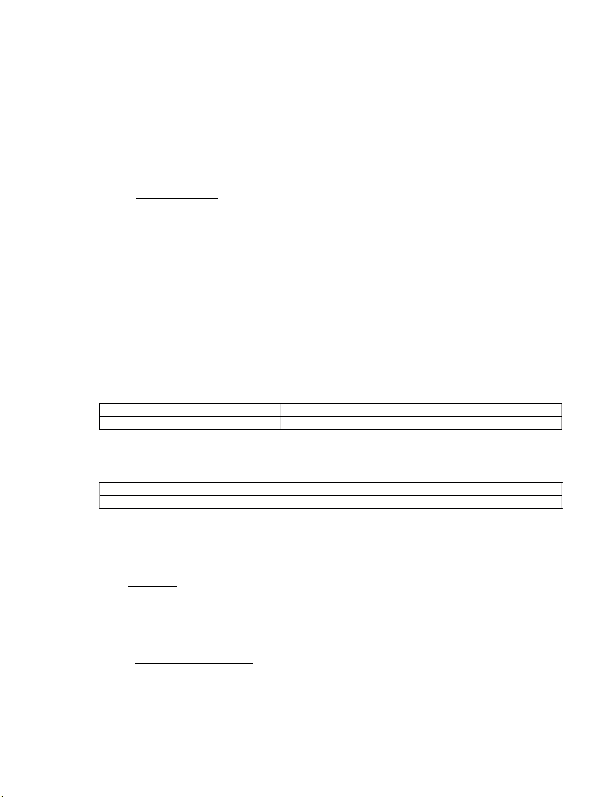
SPT SUPER DOME
COBB LED DOME LIGHT
P/N – SPTSDLB/SPTSDLC
14 volt
SPT SUPERDOME
By Superior Panel Technology
FOREWORD
This manual provides information intended for use by persons who, in accordance with current
regulatory requirements, are qualified to install this equipment. If further information is required,
please contact:
Superior Panel Technology
PO Box 1562 Chesterfield, VA 23832
Phone: 562-776-9494
Copyright 2019
Revision A, June 10, 2019 1 Manual Number SPTSDL-1

REVISION HISTORY
Rev. Date Approved Detail
A 06/10/19 WB Initial release.
TABLE OF CONTENTS
SECTION 1 GENERAL DESCRIPTION
1.1 INTRODUCTION
1.2 TECHNICAL SPECIFICATIONS
1.2.1 ELECTRICAL ATTRIBUTES
1.2.2 PHYSICAL ATTRIBUTES
SECTION 2 PRE-INSTALLATION CONSID
2.1 COOLING
2.2 EQUIPMENT LOCATION
2.3 ROUTING OF CABLES
SECTION 3 INSTALLATION PROCEDURES
3.1 GENERAL INFORMATION
3.2 UNPACKING AND INSPECTING
3.3 CABLE HARNESS
3.3.1 WIRE GAUGE SELECTION
3.3.2 WIRE ASSIGNMENT INFORMATION
3.3.3 HARNESS VERIFICATION
3.4 MOUNTING
3.5 INSTALLATION COMPLETION
SECTION 4 CONFORMANCE
4.1 CONTINUED AIRWORTHINESS STATEMENT
SECTION 5 WARRANTY
Revision A, June 10, 2019 2 Manual Number SPTSDL-1
SECTION 1 GENERAL DESCRIPTION
1.1 INTRODUCTION
The SPTSDLB OR SPTSDLC here on out will be referred to as the “SPTSDL”. This is the same exact
unit with the exception of the color anodizing of the front face plate (B=BLACK, C=CLEAR).
The SPTSDL Is an ultra-bright Dome light that can be used in a variety of aircraft locations: Cabin,
Baggage, Door entry, etc. The SPTSDL super dome provides a bright, wide angle, cool-white flood
light. A dimmer is highly suggested for use with this light. The recommended dimmer is the Superior
Panel Technology dimmer model SPTPWMLEDS. This dimmer will provide even, full-range dimming
from barely visible to full bright. This dimmer has a buillt in circuit breaking off switch which allows
you to connect directly to a battery with an inline fuse so that you to turn on the light without turning
on the master switch (if desired).
1.2 TECHNICAL SPECIFICATIONS
1.2.1 ELECTRICAL ATTRIBUTES
Input Voltage: 14-VDC
Input Power: 4 watts max; .25 amps @ 14 VDC
Table 1.1
1.2.2 PHYSICAL ATTRIBUTES
Weight: 1.41 oz
Dimensions: (not including connector) 2 inches wide X 3.33 inches long X .25 inches thick
SECTION 2 PRE-INSTALLATION CONSIDERATIONS
2.1 COOLING
No external cooling is required. The unit will become warm when in use. This is normal and within
operational parameters. No special mounting considerations are required; however, mounting to a
metal surface can help dissipate any heat generated and extend the life of the product.
2.2 EQUIPMENT LOCATION
The SPTSDL Super Dome Cobb LED light is designed for mounting flexibility, allowing for installation in
the cockpit, cabin, baggage compartment, or under seat lighting. Another great installation location is
in gullwing doors as puddle lights, for example the doors in a Vans RV-10.
Revision A, June 10, 2019 3 Manual Number SPTSDL-1

2.3 ROUTING OF CABLES
Avoid sharp bends in cabling and routing near aircraft control cables. Avoid close proximity and contact
with aircraft structures, avionics equipment or other obstructions that could chafe wires during flight
and cause undesirable effects.
SECTION 3 INSTALLATION PROCEDURES
3.1 GENERAL INFORMATION
This section contains interconnect diagrams, mounting dimensions and other information pertaining to
the installation of the SPTSDL. After installation of cabling and before installation of the equipment,
ensure that power and ground are applied to the proper wire leads as described in the wiring
description.
3.2 UNPACKING AND INSPECTING EQUIPMENT
When unpacking this equipment, make a visual inspection for evidence of any damage that may have
occurred during shipment. The following parts should be included:
Equipment Provided:
a. Super Dome Cobb LED Light SPTSDL
b. Two 6/32 100 degree stainless c/s screws
c. Two 6/32 nylon locknuts
e. Pulse width modulation dimmer (IF ORDERED) SPTPWMLEDS
Equipment Not Provided:
a. Cable Harness Wire
b. Circuit Breaker Recommend 1 amp (14v sys)
3.3 WIRING
Use the appropriate wire gauge size as indicated in table 3.1 below to bring the ground wire to the
lamp to connect to the black wire. Bring a second wire from the 14V DC power source (normally the
output from SPT's PWM dimmer-yellow screw) and connect to the red wire. Refer to Section 2: Pre-
Installation Considerations, for routing precautions.
3.3.1 WIRE GAUGE SELECTION
Use of PTFE, ETFE, TFE, Teflon or Tefzel insulated wire is recommended for aircraft use.
The wire harness should utilize 20-22 AWG stranded wire. Refer to table 3.1 below.
Wire Gauge Wire Length
20 AWG stranded wire >14 ft
22 AWG stranded wire <14 ft
TABLE 3.1
Wire Gauge and Length
Revision A, June 10, 2019 4 Manual Number SPTSDL-1

3.3.2 WIRE ASSIGNMENT INFORMATION
INPUT POWER:
Red wire – Positive DC input +14 VDC power
Black wire – Negative DC input / ground
3.3.3 HARNESS VERIFICATION
WARNING:
Failure to install aircraft power and ground wires in the proper wiring configuration will
permanently damage the unit.
Once the cable harness is prepared, prior to connecting the SPTSDL, activate the aircraft
power bus and use a multimeter to verify that aircraft power and ground is supplied with
appropriate voltage on the proper wire to be connected to the SPTSDL.
3.4 MOUNTING
Prepare the panel cutout using the dimensions on the hole cutout drawing below. It is best practice to
first use the aluminum Super Dome frame as a marking guide using a sharpie fine point marker or
mechanical pencil to locate where to drill the 9/64” holes mounting holes. This is easily preformed by
holding the front face of the SuperDome toward the panel to be drilled. Then simply mark the center
point between the two mounting holes to locate the center point for the 1.5” holesaw. The depth of the
1.5” hole needs to be at least 1/2” for clearance for an electronic component and wires.
Revision A, June 10, 2019 5 Manual Number SPTSDL-1

FIGURE 3.2
SPTSDL Outline Drawing
3.5 INSTALLATION COMPLETION
Prior to operating the unit in the aircraft, it is recommended to verify the output and functionality of the
unit.
SECTION 4 CONFORMANCE
4.1 CONTINUED AIRWORTHINESS STATEMENT
No periodic scheduled maintenance or calibration is necessary for continued airworthiness of the SPTSDL
Super Dome LED Light. If the unit fails to perform to specifications, the unit must be removed and
serviced by Superior Panel Technology.
SECTION 5 WARRANTY
5.1 WARRANTY
SPT will repair or replace at its expense and at its option any SPT Super Dome light manufactured by SPT
which in the normal use has proven to be defective in workmanship or material, provided that the
customer returns the product prepaid to SPT along with proof of purchase of the product within a 2 year
period and provides SPT with reasonable opportunity to verify the alleged defect by inspection. SPT will
not be responsible for any asserted defect which has resulted from misuse, abuse or over stressing
above published specifications. SPT will under no circumstances be liable for incidental or consequential
damages resulting from the defective products. This warranty is SPT's sole warranty and sets forth the
customer's exclusive remedy with respect to defective products. All other warranties, expressed or
implied, whether of merchantability, fitness for purpose, or otherwise, are expressly disclaimed by SPT.
Revision A, June 10, 2019 6 Manual Number SPTSDL-1
This manual suits for next models
2
Table of contents
Popular Work Light manuals by other brands


PowerSmith
PowerSmith PWLD080T Operator's manual

MaxLite
MaxLite 73683 installation instructions

Heitronic
Heitronic Trend 27867 Installation and operating instructions

Monzana
Monzana Gore MZCL10 manual

EINHELL
EINHELL TE-CL 18/2000 LiAC Original operating instructions

Bayco
Bayco NIGHTSTICK Dual-Light Xtreme Lumens... instruction manual