SPX FLOW Power Team HS2000 User manual

SPX Hydraulic Technologies
5885 11th Street
Rockford, IL 61109-3699 USA
Tech Services: (800) 477-8326
Fax: (800) 765-8326
Order Entry: (800) 541-1418
Fax: (800) 288-7031
powerteam.com
Operating Instructions for:
HS2000
HS3000
1
© SPX FLOW, Inc. Form No. 1000665
Rev. 0 Sept. 9, 2019
Hydraulic Spreader
Max. Pressure: 690 bar (10,000 psi)
Unit Weight: HS2000 = 2.17 kg (4.8 lb)
HS3000 = 9.98 Kg (22 lb)

2
© SPX FLOW, Inc. Form No. 1000665
Rev. 0 Sept. 9, 2019
Table of Contents
Description. . . . . . . . . . . . . . . . . . . . . . . . . . . . . . . . . . . . . . . . . . . . . . . . . . . . . . . . . . . .3
Safety Symbols and Denitions............................................4
Safety Precautions .....................................................4
Initial Setup ...........................................................6
Operating Instructions ...................................................7
Performance Specications...............................................7
General Maintenance ...................................................8
Troubleshooting Guide ..................................................9
Power Team Facilities & Contacts .........................................11
Declaration of Conformity ...............................................12
3
© SPX FLOW, Inc. Form No. 1000665
Rev. 0 Sept. 9, 2019
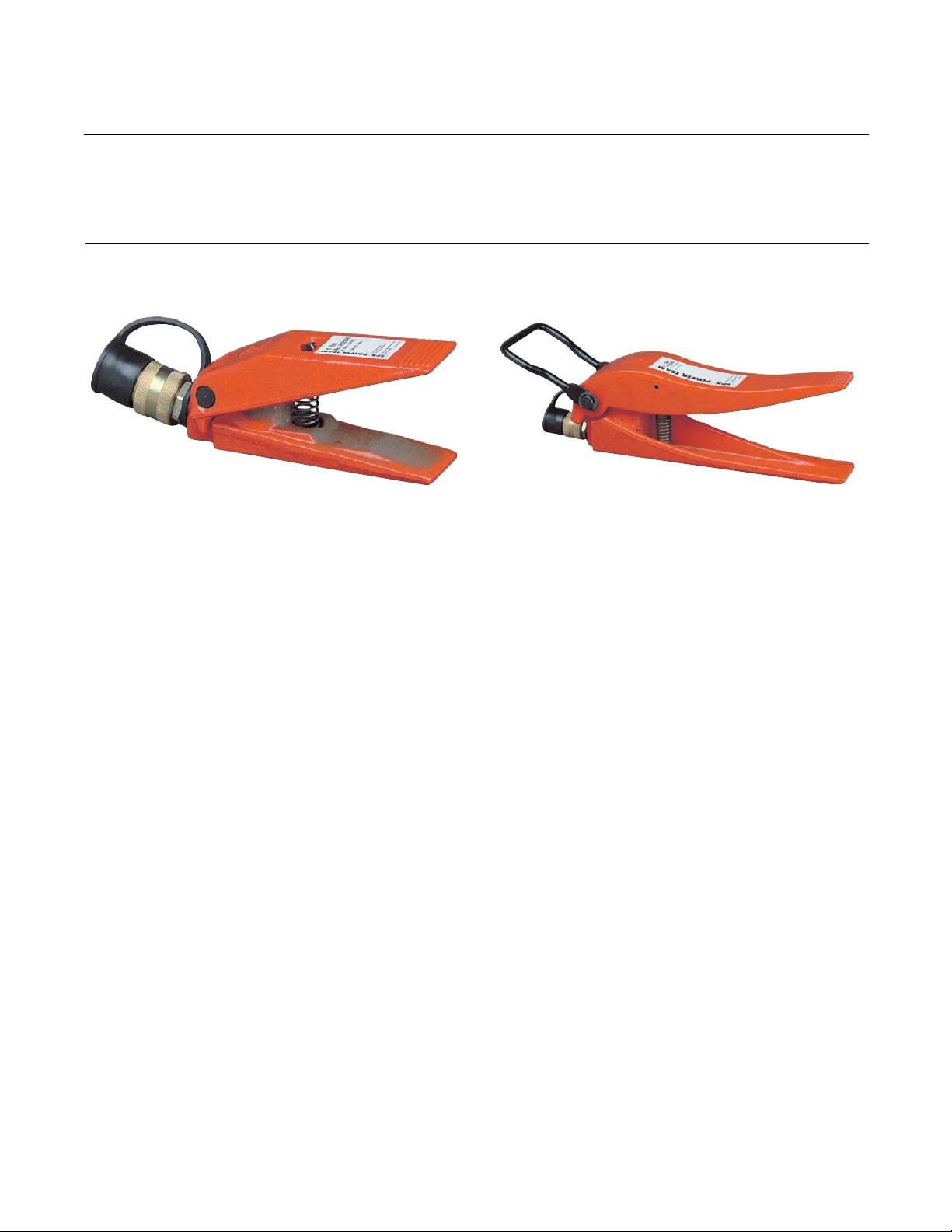
Description
Figure 1. HS2000 Figure 2. HS3000
HS2000 Hydraulic Spreader
See Figure 1. HS2000 Hydraulic Spreader is well
suited for lifting, clamping, or spreading tasks.
HS3000 Hydraulic Spreader
See Figure 2. HS3000 Hydraulic Spreader is well
suited for lifting, clamping, or spreading tasks.
Hydraulic spreaders (HS2000 and HS3000) have been developed to separate heavy
materials or rebar and straightening tasks alike. The HS2000 has a 19 cm (4 in.) jaw
spread and rated at 690 bar (10,000 psi). The HS3000 has a 29 cm (11.5 in.) spread
and also has 690 bar (10,000 psi) rating.
NOTE:
• For a detailed parts list or to locate a Power Team Authorized Hydraulic Service Center, contact
your nearest Power Team facility. A list of all Power Team facilities is located at the end of this
document.
• Carefully inspect the tool upon arrival. The carrier, not the manufacturer, is responsibile for any
damage resulting from shipment.

4
© SPX FLOW, Inc. Form No. 1000665
Rev. 0 Sept. 9, 2019
The safety signal word designates the degree or level of hazard seriousness.
: Indicates an imminently hazardous situation which, if not avoided, will result in death or
serious injury.
: Indicates a potentially hazardous situation which, if not avoided, could result in death or
serious injury.
: Indicates a potentially hazardous situation which, if not avoided, may result in minor or
moderate injury.
CAUTION: Used without the safety alert symbol indicates a potentially hazardous situation which, if
not avoided, may result in property damage.
IMPORTANT: Important is used when action or lack of action can cause equipment failure, either
immediate or over a long period of time.
Safety Symbols and Denitions
• The following procedures must be performed by qualied, trained personnel who
are familiar with this equipment. Operators must read and understand all safety
precautions and operating instructions included with the device. If the operator
cannot read these instructions, operating instructions and safety precautions must
be read and discussed in the operator's native language.
• These products are designed for general use in normal environments. These
products are not designed for use in special work environments such as: explosive,
ammable, or corrosive. Only the user can decide the suitability of this product in
these conditions or extreme environments. Power Team will supply information
necessary to help make these decisions. Consult your nearest Power Team facility.
• Safety glasses must be worn at all time by the operator and anyone within sight of
the unit. Additional personal protection equipment may include: face shield, goggles,
gloves, apron, hard hat, safety shoes, and hearing protection.
• The owner of this tool must verify that safety-related decals are installed, maintained,
and replaced if they become hard to read.
• Shut OFF the motor before opening any connections in the system.
• The guide cannot cover every hazard or situation so always do the job with SAFETY
FIRST.
• When extending a spreader under load, always insure that the coupler(s) or
port thread(s) have not been damaged or do not come in contact with any rigid
obstruction. If this condition does occur, the coupler’s attaching threads may
become stripped or pulled from the spreader resulting in instant release of high
pressure hydraulic uid, ying objects, and loss of the load. All of these conditions
could cause serious injury or death. Never use a spreader with bent or damaged
couplers or damaged port threads.
• Always support the base against a rigid, at surface at least 75% as large as the
hydraulic spreader base for stability.
Safety Precautions
WARNING
WARNING
5
© SPX FLOW, Inc. Form No. 1000665
Rev. 0 Sept. 9, 2019
• Avoid o-center loads which could damage the hydraulic spreader and/or cause loss
of the load, possibly causing serious injury or death.
• Control the load at all times. Do not drop the load.
• The user must be a qualied operator familiar with the correct operation,
maintenance, and use of the spreader. Lack of knowledge in any of these areas can
lead to personal injury.
• Wear safety glasses at all times.
• Read and understand all safety and warning decals and instructions.
• Use only approved hydraulic uid. Hoses, seals and all components used in a
system must be compatible with the hydraulic uid used.
• Do not exceed the rated capacities of the spreader. Excess pressure can result in
personal injury.
• Inspect each spreader and coupler before each shift or usage to prevent unsafe
conditions from developing. Do not use cylinders if they are damaged, altered or in
poor condition. Never use extreme heat to disassemble a hydraulic spreader. Metal
fatigue and/or seal damage will result and can lead to unsafe operating conditions.
Safety Precautions continued
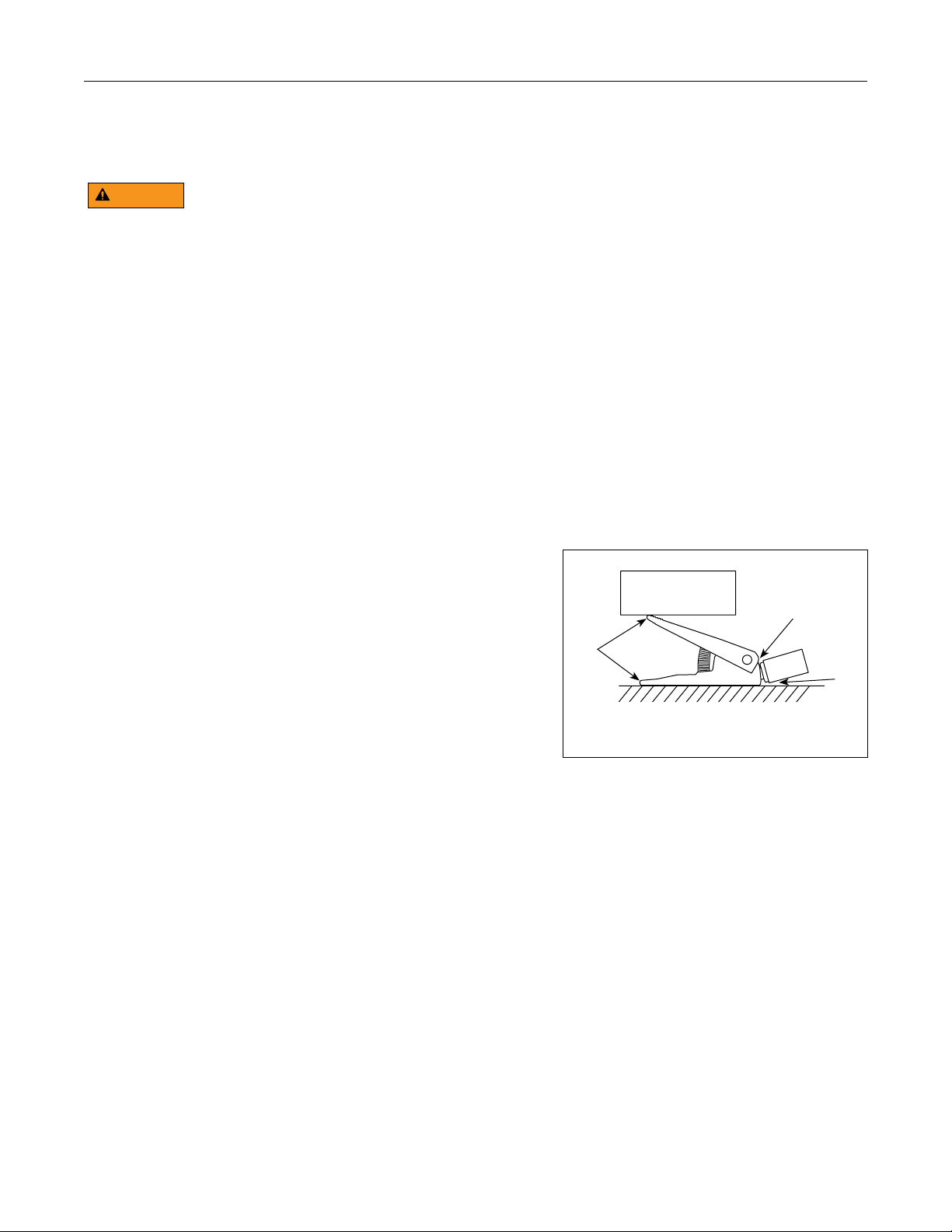
• Avoid pinch points or crush points that can be
created by the load or parts of the spreader.
• To help prevent material fatigue if the spreader
is to be used in a continuous application,
the load should not exceed 85% of the rated
capacity or stroke. Hydraulic spreaders should
not be continuously operated to the stops
without a load.
• A spreader must be on a stable base which
is able to support the load while pushing or
lifting.
• To help prevent personal injury, use shims, friction material or constraints to prevent
slippage of the base or load.
• Do not set poorly-balanced or o-center loads on a spreader. The load can tip or the
spreader can "kick- out" and cause personal injury.
• If this component is used to lift, lower, or separate loads, be certain that the load is
under operator control at all times and that others are clear of the load. Do not drop
the load.
• As the load is lifted, use blocking or cribbing to guard against a falling load or a load
that will come together after being spread apart. All personnel must be clear of the
load before lowering.
LOAD
* = PINCH POINTS
*
*
*
WARNING

6
© SPX FLOW, Inc. Form No. 1000665
Rev. 0 Sept. 9, 2019
Initial Setup
1. Remove all packing materials from the assembled unit.
2. Inspect the unit upon arrival. The carrier, not the manufacturer, is responsible for any
damage resulting from shipment.
IMPORTANT:
• Keep the spreader clean at all times.
• While at a job site, when the spreader is not in use, keep the piston rod fully
retracted and upside down.
• Use an approved, high-grade pipe thread sealant to seal all hydraulic connections.
Teon tape can be used if only one layer of tape is used and it is applied carefully
(two threads back) to prevent the tape from being pinched by the coupler and broken
o inside the pipe end. Any loose pieces of tape could travel through the system and
obstruct the ow of uid or cause jamming of precision-t parts.
• Use only Power Team hydraulic uid. Never use brake or transmission uids.
• Always use protective covers on disconnected quick couplers.
• Limiting the stroke will prolong spring life of this tool.
• Limiting the stroke and pressure on spreaders will also prolong their life.
Introduction
These instructions are written to help you, the user, more eectively use and maintain your hydraulic
spreader. If any questions, please call your nearest Power Team facility (see listing).
NOTE: For a detailed parts list or to locate a Power Team Authorized Hydraulic Service Center,
contact your nearest Power Team facility. A list of all Power Team facilities is located at the end of this
document.
Some of the information included in these instructions was selected from A.N.S.I. B30.1 and applies
to the construction, installation, operation, inspection and maintenance of hydraulic spreaders. It is
strongly recommended that you read A.N.S.I. B30.1 to answer any questions not covered in these
instructions. The complete A.N.S.I. B30.1 standard which contains additional information can be
obtained at a nominal cost from the American Society of Mechanical Engineers, United Engineering
Center, 345 East 47th, New York, New York 10017.
An inspection checklist (Form No. 105503) is available on request from your nearest Power Team
facility.
System Evaluation
The hydraulic spreader, hoses, couplings and pump all must be rated for the maximum operating
pressure of 690 bar (10,000 psi), correctly connected and compatible with the hydraulic uid used. An
unmatched system can cause the system to fail and serious injury. Please contact your nearest Power
Team facility with any technical questions or clarications as required.

7
© SPX FLOW, Inc. Form No. 1000665
Rev. 0 Sept. 9, 2019
Operating Instructions
Performance Specications
Inspection
Before each use, visually inspect for the following items:
• Cracked or damaged spreader
• Excessive wear, bending, damage, or insucient thread engagement
• Leaking hydraulic uid
• Scored or damaged piston rod
• Loose bolts, pins, or ttings
• Modied, welded, or altered equipment
• Bent or damaged couplers or port threads
Note: If any of the above conditions are present, do not use the tool.
Preventive Maintenance (yearly or sooner, if the spreader condition suggests damage)
Visual examination by the operator or other designated personnel with a dated and signed
equipment record.
Operation
Do not exceed the maximum lift and stroke of the tool.
HS2000 HS3000
Maximum Rated Capacity 907 kg (1 ton) 1360 kg (1.5 ton)
Maximum Spread Capacity 10 cm (4 in.) 29.2 cm (11.5 in.)
Minimum Clearance Required 1.5 cm (.6 in.) 3.2 cm (1.25 in.)
Cubic CM. (cu.in) of Fluid Required 10.3 (0.63) 57.4 (3.5)
Table 1. HS2000 & HS3000 Specifications

8
© SPX FLOW, Inc. Form No. 1000665
Rev. 0 Sept. 9, 2019
General Maintenance
• Repairs and maintenance are to be performed in a dust-free area by a qualied
technician.
12
3
4
5
6
Figure 3. HS2000 Components
Item Description
1 Trade Name Decal
2 Upper Jaw
3 Extension Spring
4 Lower Jaw
5 Pivot Pin
6 Ram Half Coupler (w/Dust Cap)
12
3
4
5
6
7
Figure 4. HS3000 Components
Item Description
1 Trade Name Decal
2 Upper Jaw
3 Extension Spring
4 Lower Jaw
5 Pin
6 Ram Half Coupler (w/Dust Cap)
7 Handle
Inspection
See Figure 3 and Figure 4. Before each use,
visually inspect for the following items:
• Cracked or damaged spreader.
• Excessive wear, bending, damage, or
insufficient thread engagement.
• Leaking hydraulic fluid.
• Scored or damaged piston rod.
• Loose bolts, pins, or fittings.
• Modified, welded, or altered equipment.
• Handle.
Preventive Maintenance
Visual examination by the operator or other
designated personnel with a dated and signed
equipment record should be done yearly (or
sooner) if the spreader condition suggests
damage.
Storage
Store the unit in a dry, well-protected area where
it will not be exposed to corrosive vapors, debris,
or other harmful elements. If a unit has been
stored for an extended period of time, it must be
thoroughly inspected before it is used.
WARNING

9
© SPX FLOW, Inc. Form No. 1000665
Rev. 0 Sept. 9, 2019
• Repair work or troubleshooting must be performed by qualied personnel who are familiar
with this equipment.
• Disconnect the power supply before removing the electrical cover. Electrical work should be
performed by a qualied electrician.
• Check for system leaks by using a hand pump to apply pressure to the suspect area. Watch
for leaking uid and follow it back to its source. Never use your hand or other body parts to
check for a possible leak.
Notes:
• For a detailed parts list or to locate a Power Team Authorized Hydraulic Service Center, contact your
nearest Power Team facility.
• Plug the outlet ports of the pump when checking for leakage to determine if the leakage is in the
pump, in the cylinder, or in the tool.
Troubleshooting Guide
Problem Cause Solution
Erratic action. 1. Air in system or pump
cavitation.
1. Add uid, bleed air and check for
leaks.
2. Internal leakage in double-
acting cylinders or external
leaking in single-acting
cylinders.
2. Replace worn packings. Check for
excessive contaminations or wear.
Replace contaminated uid as
necessary.
3. Spreader sticking or binding.
3. Check for dirt or leaks. Check for
bent, misaligned, worn parts or
defective packing.
Spreader does not move. 1. Loose couplers.
1. Tighten couplers. Make sure all
couplers are fully screwed.
2. Faulty coupler.
2. Verify that female coupler is
not locked up (ball wedged into
seat). Replace both female and
male couplers.
3. Improper valve position.
3. Close release valve or shift to
new position.
4. Low or no hydraulic uid in
pump reservoir.
4. Fill and bleed the system.
5. Air-locked pump.
5. Prime pump per pump operating
instructions.
6. Pump not operating.
6. Check pump's operating
instructions.
7. Load is above the capacity of
the system.
7. Use the correct equipment.
WARNING

10
© SPX FLOW, Inc. Form No. 1000665
Rev. 0 Sept. 9, 2019
Problem Cause Solution
Spreader extends only
partially.
1. Pump reservoir is low on
hydraulic uid.
1. Fill and bleed the system.
2. Load is above the capacity of
the system.
2. Use the correct equipment.
3. Piston rod binding.
3. Check for dirt or leaks. Check for
bent, misaligned, worn parts, or
defective packing.
Spreader moves slower
than normal.
1. Loose connection or coupler.
1. Tighten.
2. Restricted hydraulic line or
tting.
2. Clean and replace if damaged.
3. Pump not working correctly.
3. Check pump operating
instructions.
4. Cylinder seals leaking.
4. Replace worn seals. Check for
excessive contamination or wear.
Spreader moves but does
not maintain pressure.
1. Leaky connection.
1. Clean, reseal with thread sealant
and tighten the connection.
2. Cylinder seals leaking.
2. Replace worn seals. Check for
excessive contaminated uid as
necessary.
3. Pump or valve malfunctioning.
3. Check pump or valve operating
instructions.
2. Loose connections.
2. Clean, reseal with thread sealant
and tighten connection. Make
certain all connections are fully
secured.
Spreader will not retract
or retracts slower than
normal.
1. Pump release valve closed.
1. Open pump release valve.
2. Loose couplers.
2. Tighten couplers.
3. Blocked hydraulic lines.
3. Clean and ush.
4. Weak or broken retraction
springs.
4. Send to service center for repair.
5. Spreader damaged internally.
5. Send to service center for repair.
6. Pump reservoir too full.
6. Drain hydraulic uid to correct
level.
Troubleshooting Guide continued

11
© SPX FLOW, Inc. Form No. 1000665
Rev. 0 Sept. 9, 2019
POWER TEAM FACILITIES & CONTACT
www.spxow.com
SPX Flow Customer Service:
(800) 541-1418
North America Headquarters
5885 11th Street
Rockford, IL 61109
USA
Customer Service/Order Entry
Tel: +1 800 541 1418
Fax: +1 800 288 7031
Technical Services
Tel: +1 800 477 8326
Fax: +1 800 765 8326
European Headquarters
Albert Thijsstraat 12
6471 WX Eygelshoven
The Netherlands
Tel: +31 45 567 8877
SEA Headquarters
20 Pioneer Crescent #06-01
West Park BizCentral
Singapore 628555
Tel: +65 6264 4366
Fax: +65 6265 9133
India Headquarters
SPX Flow Technology (India) Pvt. Limited
Survey No. 275
Odhav, Ahmedabad - 382 415
Tel: +91-99099-85454
+91-97277-19950
China Headquarters
7F Treasury Building
1568 Huashan Road
Shanghai, 200052 China
Tel: +86 21 2208 5888
Fax: +86 21 2208 5682
Australia Headquarters
SPX Flow Technology Australia Pty Ltd
Quad 2, 6 Parkview Drive
Homebush Bay NSW 2127
Tel: +61 02 9763 4900
Fax: +61 02 9763 7888
Ft.aus.cs@spxow.com

12
© SPX FLOW, Inc. Form No. 1000665
Rev. 0 Sept. 9, 2019
Declaration of Conformity
English Original
SPX Hydraulic Technologies
5885 11
th
Street
Rockford, IL 61109-3699
United States of America
SPX Hydraulic Technologies
Andreas J. Klemm
SPX Hydraulic Technologies
Albert Thijsstraat 12
NL-6471 WX Eygelshoven
The Netherlands
EC DECLARATION OF CONFORMITY
We declare under our sole responsibility that our Hydraulic Spreader Model:
* HS2000, HS3000
to which this declaration relates are in conformity with the following:
EN, EN-ISO, ISO standards Title
Per the provisions of the Machinery Safety Directive 2006/42 EC
EN_ISO 12100 Safety of machinery, basic concepts, general principles for
design, risk assessment & risk reduction
EN 4413 Hydraulic Fluid Power –general rules and safety
requirements for systems & their components
We hereby declare that the equipment specified under * conforms to the above quoted
European Community Directive(s) and Standard(s) as per the currently valid revision.
SPX Hydraulic Technologies is certified and registered to ISO 9001: 2015.
The Netherlands September 03
rd
, 2019
------------------------------------------
Andreas J. Klemm, PhD
This manual suits for next models
1
Table of contents


