Buyers SaltDogg 1490757SSE User manual

1
9049 Tyler Blvd. • Mentor, Ohio 44060
Phone (440) 974-8888 • Fax (800) 841-8003
www.saltdogg.com
Installation Instructions
Municipal-Sized Electric Powered
Stainless Steel Hopper Spreaders
—continued inside
Table of Contents
General Information ......................................................... 1
Warranty Information ....................................................... 1
Safety Precautions ........................................................... 2
Installation Instruction ...................................................2-8
Spreader Operation ......................................................2-8
Spreader Maintenance ..................................................2-8
Optional Equipment ......................................................... 5
Repair Parts ................................................................ 6-8
GENERAL INFORMATION
SPREADER WARRANTY INFORMATION
This warranty replaces all previous warranties and no employee
of this company is authorized to extend additional warranties, or
agreements, or implications not explicitly covered herein. Buyers
Products Company warrants all parts of the product to be free
from defects in material and workmanship for a period of one (1)
year from the date of installation. Parts must be properly installed
and used under normal conditions. Normal wear is excluded.
Any part which has been altered, including modifications,
misuse, accident, or lack of maintenance will not be considered
under this warranty. The sole responsibility of Buyers Products
Company under this warranty is limited to repairing or replacing
any part(s) which are returned, prepaid, 30 days after such
defect is discovered, and returned part(s) are found to be
defective by Buyers Products Company. Authorization from
Buyers Products Company must be obtained before returning
any part. The following information must accompany defective
parts returned to Buyers Products Company: RMA#, spreader
model, serial number, date installed, and distributor from whom
purchased. Buyers Products Company shall not be liable for
damage arising out of failure of any unit to operate properly, or
failure, or delay in work, or for any consequential damages. No
charges for transportation or labor performed on any part will
be allowed under this warranty.
MODEL NO.
OVERALL
LENGTH
OVERALL
WIDTH
OVERALL
HEIGHT
EMPTY
WEIGHT
CAPACITY
CU. YDS
1490757SSE 143" 82" 62.3" 2,932 lbs. 7.0
1490957SSE 167" 82" 62.3" 3,433 lbs. 9.0
1. Recommended Vehicle Requirements
Buyers Municipal-Sized Hopper Spreaders are intended
for spreading abrasives and/or chemicals, primarily for
ice and snow control. They are intended for installation
on truck chassis or dump bodies with GVWR 26,000 lbs.
Spreaders are intended to be mounted on trucks with
Cab To Axle/Tandem Dimension minimum of 84 inches.
IMPORTANT
The Cab to Axle/Tandem dimensions are only guidelines.
Consult federal, state and local weight laws and chassis
manufacturer’s ratings to ensure neither government weight
restrictions, nor GVWR and GAWRs are exceeded.
2. Average Material Weights
MATERIAL WEIGHT (POUNDS PER CUBIC YARD)
#1 Rock Salt - 950
#2 Rock Salt - 1,215
Coarse Sand - Dry 2,565
3. Recommended Fastener Torques
Maintain all fastener torques as shown in the following
table. Failure to do so may cause injury to persons.
SAE GRADE 2 ft-lbs SAE GRADE 5 ft-lbs
5/16-18 11 18
3/8-18 19 31
3/8-24 24 46
7/16-14 30 50
1/2-13 45 75
9/16-12 66 110
5/8-11 93 150

2
SAFETY PRECAUTIONS
WARNING
Observe the following Safety Precautions before, during and
after operating this spreader. By following these precautions
and common sense, possible injury to persons and potential
damage to this machine may be avoided.
WARNING
The lifting device must be adequately rated to lift a payload
equal to or greater than the spreader weight. See page 1 for
spreader weights. Empty the spreader before lifting.
1. Read this entire Owner’s Manual before operating this
spreader.
2. Read all safety decals on the spreader before
operating the spreader. IF DECALS BECAME DEFACED-
REPLACE!
3. Check to make sure all safety guards are securely
mounted into place before operating this spreader.
4. Verify that all personnel are clear of the spreader spray
area before starting or operating this spreader.
5. Keep all loose clothing, hair, jewelry and limbs clear of
the spreader before starting or operating this spreader.
6. Do not over-load your vehicle beyond payload limits. If
there are any questions, contact the vehicle manufacturer.
7. Do not adjust, clean, oil or unclog material jams
without first turning off the spreader.
8. Do not climb on or in the spreader during operation.
Do not ride on the spreader while the vehicle is in motion.
9. Make sure the spreader is securely fastened to the
vehicle in accordance with this manual.
10. Do not operate a spreader that is in need of
maintenance or repairs.
11. Always disconnect the wire harness before removing
or replacing any electrical components.
12. Make sure that spreader solidly supported when it is
being mounted, dismounted or stored.
INSTALLATION INSTRUCTIONS
Dump Body Mounting
1. Remove the tailgate from the vehicle if applicable.
2. Lift the spreader using the (4) lifting loops in the
corners of the hopper.
3. Center the spreader in the vehicle. Spreader sills must
overhang 20" beyond the back end of the vehicle.
4. If the dump body is not flat, it is suggested that the
spreader be placed on two 1" x 6" hardwood boards. This
will evenly distribute the weight of the loaded spreader on
the entire cross channels.
5. The spreader may be secured to the vehicle by using
Tie-Down Kit Buyers part #3010548 (sold separately).
6. Periodically check that the spreader mounting
hardware is securely tightened.
Chassis Mounting
1. Hardwood wear strips usually 1" x 3" (not furnished)
must be fitted to the truck chassis.
2. The spreader should be positioned on the wooden
wear strips so hopper sills must overhang 20" beyond the
back end of the vehicle.
3. In addition a distance of approximately 4"-6" must be
left between the truck cab and the front of the hopper.
This will help facilitate any future servicing of the conveyor
chain.
4. Qualified installer must fabricate suitable angles to
attach hopper cross members to track’s frame. DO NOT
weld mounting angles to the truck frame. Doing so can
cause fatigue cracking of the truck frame.
Chute Installation
1. Bolt chute to Chute Guide using screws, washers
and nuts. Place washers between Chute Guide tabs and
Chute brackets.
2. Swing chute towards vehicle. Connect chute to the
hopper by engaging two latches into corresponding holes
in chute brackets.
3. Chute heights can be adjusted by sliding lower chute
assembly up or down inside of upper chute assembly.
Adjustment slots are spaced by 3". Secure lower chute
assembly using all 4 carriage bolts provided. Make sure
all four bolts are used for installation. To increase ground
clearance cut upper chute as shown and use lower slots
in bottom chute.
5"
CUT ALONG THIS LINE
Fig. 1

3
WARNING
Do not drill holes into fuel tanks, fuel lines, through electrical
wiring, etc. that may be damaged by drilling. To insure good
performance of your spreader, check the condition of truck’s
electrical system. Using digital voltmeter, check alternator
and battery voltage. With engine running and head lights and
heater fan ON good voltage reading should fall between 13.0
and 15.3 volts. If voltage reading falls out of this range, check
and adjust your electric system.
IMPORTANT
Make sure all wires securely attached to vehicle or spreader.
Use wire ties and/or wire clamps to attach wires. All excess
wires must be rolled into bungles and attached to vehicle or
spreader.
CAUTION
Do not mount controller in the way of air bag deployment!
Control Box & Vehicle Wiring Harness Installation
Make sure you have connected the proper wire color.
This is wire ground electrical system! No connections to
truck’s frame or body allowed!
NOTE: Always disconnect battery before attempting to
install electrical components on your vehicle.
1. Mount the controller in a convenient location in the
truck cab. It is recommended not to mount the controller
directly in front of heat vents. Allow ample air space
around controller.
2. Route both wire harnesses into truck cab through
firewall (it maybe necessary to drill holes). Install
grommets to protect wire harnesses. Insulate hole to
avoid water leaks.
3. Insure no wires are nicked or damaged during installation.
4. Connect the 4-pin connector on the wire harness to
the control box 4-pin connector.
5. Connect the 2-pin connector on the power cable to the
mating control box mating connector.
6. Connect wire harness single connectors to control box
connectors.
7. Connect fuse connector to the fuse terminal or ignition
switch (5 AMP max).
8. Lay out a path for the power cable to the battery, use
quick ties to secure power cable. DO NOT CONNECT TO
BATTERY AT THIS TIME!
9. Lay out path for wire harness to the rear of the vehicle.
It is recommended to stay clear of the exhaust system.
Excess heat can damage the wire harnesses. Use quick
ties to secure harness to underbody.
10. Connect the wire harness to the motors. Make sure
wire colors on wire harness match colors on the motors.
11. Thoroughly clean battery terminals. Make sure
battery terminals have no tarnish or corrosion. DO
NOT CONNECT WIRE HARNESS TO DAMAGED
OR CORRODED TERMINALS! IT MAY RESULT IN
OVERHEATING, LOST POWER AND POTENTIAL
CONTROLLER DAMAGE!
12. Connect the power cable directly to the battery.
13. Insure all functions of the controller are working
properly.
14. Observe chain moving in proper direction. If direction
is wrong reverse wires between Motor and Wire Harness.
15. Optional spot light (5 AMP max) can be installed on
spreader. Remove cap from single white wire. Connect
3016934
3016944
0203700
3035935
CB150PB
3001379
BATTERY POSITIVE
BATTERY NEGATIVE
CONNECT TO FUSE
OR WIRE IN FUSE PANEL,
CONTROLLED BY
IGNITION SWITCH

4
9049 Tyler Blvd. • Mentor, Ohio 44060
Phone (440) 974-8888 • Fax (800) 841-8003
www.saltdogg.com
light to this wire and trucks frame.
SPREADER OPERATION
The spread pattern and the amount of material dispensed
will depend on the following factors:
• Conveyor speed.
• Spinner RPM.
• Feed gate door position.
• Baffle settings.
CAUTION
Always follow the following precautions so as not to cause
damage to the spreader.
• If the conveyor chain does not move because of dense
material or a material jam, remove all material from the hopper
and free the chain.
• If the material in the hopper freezes, move the spreader into
a warm area to thaw.
• To prevent the feed chain from freezing, do not store material
in the spreader.
• The gearbox is designed to only accept torque from the
electric motor. Therefore, DO NOT ATTEMPT TO FREE THE
CONVEYOR BY USING A PIPE OR SIMILAR TOOL TO MOVE OR
DISLODGE THE CHAIN. This action will void all warranties.
CAUTION
Do not over-tension the conveyor chain. This can cause
damage to the chain, bearings, and gear motor.
• Empty the spreader of all ice control material when not in use
to prevent a frozen feed chain & damage due to corrosion.
• Wash out the spreader when it is not in use. At the end of
the season wash out the spreader to remove all ice control
materials. Thoroughly dry all metal surfaces. Re-paint and oil
all previously painted surfaces and chains to protect from rust.
Properly store the spreader for the next season.
IMPORTANT
Check the Feed Chain tension periodically. Proper chain tension
is illustrated below. Be sure the chain is tensioned equally
on both sides. This adjustment is made on each side of the
spreader at the idler bearing.
Below are illustrations that show the baffles effect on the
spread pattern as viewed from the top of the spinner disk.
SPREADER MAINTENANCE
• Grease the following components regularly:
• Idler shaft bearings (2)
All baffles adjusted
down for a confined
spread pattern
Right baffle deflects
material down;
heavy on right side
Left baffle deflects
material down;
heavy on left side
Both internal
baffles out
Left baffle in,
Right baffle out
Right baffle in,
Left baffle out
Internal Baffle Adjustment
External Baffle Adjustment
• Drive shaft bearing (1)
• Feed Gate Jack
• Lubricate the conveyor chain at least once a week.
Use a mixture of 75% fuel oil and 25% SAE 10 oil in a
pressurized hand spray gun.
• Tighten all screw fasteners to recommended torques
after the first week of operation and annually thereafter.
If loose fasteners are found at any time, tighten to the
recommended torques. Replace any lost or damaged
fasteners or other parts immediately upon finding such
damage or loss. Check body mounting bolts every week.
Feed Chain Rear of Sill Extension
2" - 3"
21" - 25"

5
ITEM PART NO. QTY. DESCRIPTION
13010172 1WELDMENT UPPER, CHUTE
23010202 2WELDMENT, DEFLECTOR INNER
33010278 2RETAINER, DEFLECTORS INNER
4FWF025063007SS 12 WASHER, FLAT 1/4 SAE SS
5FCS025020075SS 8 SCREW, CAP 1/4-20 X 3/4 SST
6FNE025020031SS 8 NUT, NYLON INSERT 1/4-20 SST
73000269 2 WASHER, FLAT 1/2 USS, SST
83008853 2SPRING, SPINNER CHUTE BAFFLE
9FPC019000125 2 PIN, COTTER 3/16" X 1.25" ZN
10 3032824 1WELDMENT, LOWER CHUTE BOTTOM MOTOF
11 FCB037516100SS 4 BOLT, 3/8-16 X 1 CARRIAGE SST
12 FWF038100007SS 10 WASHER, FLAT 3/8 USS SST
13 FWL038069009SS 4 WASHER, LOCK RHS-3/8 SST
14 FNH038016028SS 4 NUT, 3/8-16 HEX SST
15 FCS038016100SS 6 SCREW, HHC 3/8-16 X 1 304 SST
16 3012506 2 BAFFLE SIDE, LOWER CHUTE
ITEM PART NO. QTY. DESCRIPTION
17 FNE038016044SS 6 NUT, NYLOCK 3/8-16 X 7/16 SST
18 BCP84620SS 3 PIN, CLEVIS 3/8 X 1.125 SST
19 FPC009000075SS 3 PIN, COTTER 3/32 X 3/4 STAINLESS
20 3012507 1 BAFFLE REAR, LOWER CHUTE
21 3030222 1GEAR MOTOR .4 HP SPINNER
22 FWL031058008SS 3 WASHER, 5/16 LOCK SST
23 FCS031018063SS 3 SCREW, HHC 5/16-18 X 5/8 SST
24 3030575 1 ENCLOSURE, GEAR MOTOR CHUTE
25 3025065 1BUSHING STRAIN RELIEF
26 3030182 1HUB, SPINNER POLY
27 3007113 1 PIN, CLEVIS, 5/16 X 2-1/2, .141 HOLE ZN
28 3014994 1PIN,COTTER,1/8IN X 1IN SST
29 3030179 1SPINNER 18" POLY CW
30 FWF031075006SS 4 WASHER, 5/16 SAE SST
31 FCS031018175SS 4 SCREW, HHC 5/16-18 X 1 3/4 SS
32 FNE031018034SS 4 NUT, NYLOCK 5/16-18 SS
Repair Parts - Chute
Bill of Materials
1
2
3
4
5
6
7 8
9
10
11
12
13
14
15
16
17
18
19
20
21
22 23
24
25
26
2728
29
30
31
32

6
ITEM PART NO. QTY. DESCRIPTION
13032621 1 HOPPER WELDMENT 10 FT 57 IN SST ELECTRIC
3034751 1
HOPPER WELDMENT 12 FT 9CUYD SST ELECTRIC
23001522 4 BOLT, CARRIAGE 1/2-13X1 SST
33001523 4 NUT, HX FLNG-1/2-13 SST
43034718 1BRACKET CONNECTORS
53010131 2WIPER, RUBBER
6FWF038100007SS 14 WASHER, FLAT 3/8 USS SST
7FCS038016125SS 6 SCREW, HHC-3/8-16X 1.25 SST
8FNE038016044SS 15 NUT, NYLOCK 3/8-16 X 7/16 SST
93019694 1 ADAPTER GEAR BOX
10 3034230 1 GEAR MOTOR 3/4 HP 12VDC 280:1
11 3032660 1 DRIVE SHAFT
12 KS402 1 KEY, 1/4 X 1/4X2
13 4F32SCR 1 BEARING FLANGE 2.0 DIA, 4 HOLES SET SCREW
14 3010989 2 KEY, SQUARE 1/2" X 2 1/2"
15 3010845 2 SPROCKET DRIVE, ASSEMBLY
16 1457150 1 CHAIN, 10 FT. D667H CONVEYOR
3034759 1 CHAIN, 12 FT. D667X CONVEYOR 1.5x.25 BARS
17 3010358 1IDLER SHAFT, ASSEMBLY
18 3010603 2 BEARING, HD TAKE-UP 1.5 DIA.
19 3026276 4 SCREW HH, 3/4-10 X 3.0 FULL THREAD, SST
20 3010659 8 NUT, HEX NYLOCK 3/4-10 SST
21 3023046 2BOLT, WELDED TAKE UP
22 3023022 2SPRING CHAIN TENSION
23 3023044 2TAKE-UP NUT WELDMENT
24 FNH063011054SS 2 NUT, HH 5/8-11 X 17/32 HIGH SST
25 3010312 1FEED GATE, WELDMENT
26 3032849 1 BRACKET, CHAIN CHUTE
27 3010443 1 JACK ASSEMBLY, FEED GATE
ITEM PART NO. QTY. DESCRIPTION
28 FCS031018300SS 1 SCREW, HH CAP 5/16-18 X 3 SST
29 FNE031018034SS 1 NUT, NYLOCK 5/16-18 SS
30 FCS025020100SS 4 SCREW, CAP HEX HD 1/4-20 X 1 SST
31 FWF025063007SS 4 WASHER, FLAT 1/4 SAE SS
32 FNE025020031SS 4 NUT, NYLON INSERT 1/4-20 SST
33 1499020 1LABEL, WARNING 1
34 1499035 2LABEL, WARNING 3
35 1499030 1 LABEL, CAUTION 1 (PAYLOAD)
36 1499045 1LABEL, WARNING 4
37 3010916 1 LABEL, SERIAL NUMBER
38 3010918 1 DECAL, POINTER FEED GATE
39 3010917 1 DECAL, GAUGE FEED GATE
40 3017730 2 CROSS MEMBER, INVERTED VEE
41 3017731 2HANGER, INVERTED VEE
42 3000269 8 WASHER, FLAT 1/2 USS, SST
43 3006723 16 SCREW, HEX HD 1/2-13x1.5 GR5 SS
44 FNE050013053SS 16 NUT, NYLOCK 1/2-13 SS
45 3032805 1DEFLECTOR, INVERTED VEE
3034757 1DEFLECTOR, INVERTED VEE
46 3032688 1 GRATE SUPPORT 10 FT, BLACK
3028914 1GRATE SUPPORT, WELDMENT
47 3025824 1 COVER, BEARING 4F32SCR
48 3026277 1 PLUG, BEARING COVER
49 3011132 3 DECAL, SALT DOGG, BLK/WHT ON CLR 18X6.3125
50 FCS038016100SS 4 SCREW, HHC 3/8-16 X 1 304 SST
51 3017121 2 BRACKET, RECEPTACLE SZ8 DEUTSCH
52 3016740 2 SCREW, HHC-3/8-16 X 1/2 SST
53 FCS038016075SS 3 SCREW, HHC-3/8-16 X 3/4 SST
54 FCS050013100SS 4 SCREW, HHC-1/2-13 X 1 SST
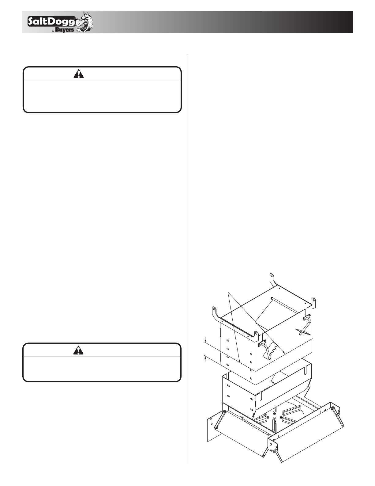
Repair Parts - Hopper Assembly
Bill of Materials
1
2
3 4
5
6 7
8
9
10
11 12
13 14 15
16
17
18
19
20
21
22
23
24
25
26
27
28
29
30
31
32
33
34
35
36
37
38
39
40
41
42 43
44
45
46
47
48
49 50
51
52
53
54

7
ITEM PART NO. QTY. DESCRIPTION
13032620 1 HOPPER ASM, 10 FT 57 IN SST ELECTRIC
3034750 1 HOPPER ASM 12 FT 9 CU YD ELECTRIC
23010180 1GUIDE, CHUTE
3FCS038016100SS 4 SCREW, HHC 3/8-16 X 1 304 SST
4FNE038016044SS 4 NUT, NYLOCK 3/8-16 X 7/16 SST
53010116 4 GRATE, WELDED HOPPER TOP
3015554 6GRATE, WELDED HOPPER TOP (6)
63032633 1 CHUTE ADJUSTBLE, LOW MOTOR
73032855 1HARDWARE KIT
Repair Parts - Spreader
Bill of Materials
1
2
3
4
5
6
7

83032854_B
9049 Tyler Blvd. • Mentor, Ohio 44060
Phone (440) 974-8888 • Fax (800) 841-8003
www.saltdogg.com
This manual suits for next models
1
Table of contents
Other Buyers Spreader manuals

Buyers
Buyers TB150BG User manual

Buyers
Buyers Salt Dogg SHPE1500 User manual

Buyers
Buyers UTVS16 User manual

Buyers
Buyers SaltDogg 14708F463211 User manual

Buyers
Buyers ATVS15A User manual

Buyers
Buyers ATVS100 User manual

Buyers
Buyers SaltDogg SHPE3000 User manual

Buyers
Buyers SaltDogg SHPE2500 Series User manual

Buyers
Buyers SaltDogg 1470601SSE User manual

Buyers
Buyers ATVS100 User manual