SPX FLOW Seital Separation SE 40CX-Q2P2 User manual

INSTRUCTION MANUAL
English
SELF-CLEANING CENTRIFUGAL SEPARATOR
Type: SE 40CX-Q2P2
FO RM NO .: 00 - 00 0 00
RE VIS IO N: 0
R EA D A ND U N D ERS T AN D T H IS M A NU AL P R I OR T O O P ER AT I NG O R S E RV I CI NG T H I S PR O DU CT .


Chapter 1
Rev. 2 of 11/02/98 SEITAL S.r.l.
Use and maintenance handbook: Centrifugal separator SE 40CX Page 1-1
USE AND MAINTENANCE HANDBOOK
Self-Cleaning Centrifugal Separator
SE 40CX
1. HANDBOOK USE
1.1. How to read the Handbook
This handbook gives information for the installation, use and maintenance of centrifugal
separator, model SE 40, for cream concentration.
The machine must be used in accordance with the Handbook specification: it is recommended
to read it with great attention before installing and setting at work the machine, without
leaving out anyone of the prescriptions reported and paying particular attention to the
messages in the “text squares”. The respect of the reported rules and recommendations permit
a safe use and appropriate service.
The use and maintenance Handbook is an integrant part of the machine: it’s necessary to
conserve it complete and in a safe place during all the machine life, also when changing the
machine user.
1.2. How to bring up-to-date the Handbook
It is recommended to bring constantly up-to-date this Handbook, integrating with eventual
other amendments, additions or modifications coming from the manufacturer.
It’s better that eventual annotations and remarks are inserted only in the space intentionally
predisposed at the end of this Handbook.

Chapter 1
SEITAL S.r.l. Rev. 2 of 11/02/98
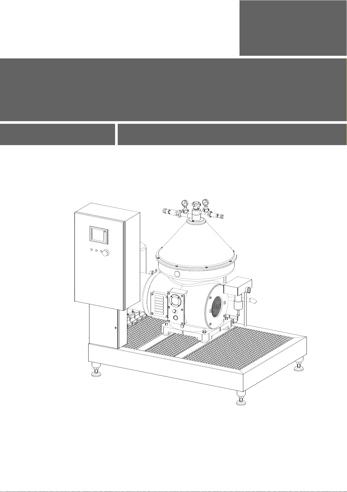
Page 1-2 Use and maintenance handbook: Centrifugal separator SE 40CX
1.3. Handbook index
1. HANDBOOK USE 1-1
1.1. HOW TO READ THE HANDBOOK........................................................................................1-1
1.2. HOW TO BRING UP-TO-DATE THE HANDBOOK.................................................................1-1
1.3. HANDBOOK INDEX .............................................................................................................1-2
2. GENERAL INFORMATION 2-1
2.1. MANUFACTURER AND MACHINE DATA.............................................................................2-1
2.2. TECHNICAL SERVICE.........................................................................................................2-1
2.3. GLOBAL ASPECTS OF SAFETY ...........................................................................................2-1
2.3.1. INSTALLATION.................................................................................................................2-1
2.3.2. WARNINGS FOR THE OPERATORS....................................................................................2-1
2.3.3. MAINTENANCE PROGRAMS.............................................................................................2-2
2.3.4. INVOLVED OPERATORS AND TECHNICIANS.....................................................................2-2
2.3.5. MAIN WORKING MODES ..................................................................................................2-2
2.3.6. FORESEEABLE ERRORS AND INCORRECT BEHAVIOURS...................................................2-3
2.3.7. LIST OF USED SYMBOLS AND WARNINGS ........................................................................2-3
2.3.8. SAFETY PRESCRIPTIONS..................................................................................................2-3
2.4. USED TERMS AND ABBREVIATIONS...................................................................................2-6
2.5. RESPONSIBILITY ................................................................................................................2-6
3. MACHINE DESCRIPTION 3-1
3.1. GENERAL DESCRIPTION ....................................................................................................3-1
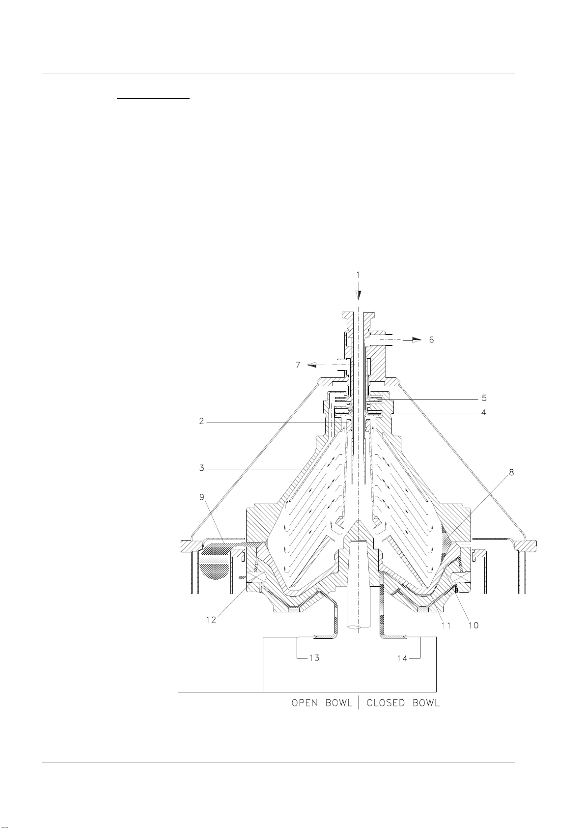
3.2. OPERATING PRINCIPLES....................................................................................................3-1
3.3. TECHNICAL CARD ..............................................................................................................3-3
3.4. NOISE LEVEL......................................................................................................................3-4
3.5. DESTINATION AND FORESEEN PLACE OF USE...................................................................3-4
3.6. IMPROPER USES AND CONTRA-INDICATIONS ...................................................................3-4
4. LIFTING, TRANSPORT, STORAGE 4-1
4.1. MACHINE DELIVERY..........................................................................................................4-1
4.2. PACKING AND UNPACKING................................................................................................4-1
4.3. LIFTING AND TRANSPORT OF THE PACKED MACHINE.....................................................4-1
4.4. LIFTING AND TRANSPORT OF THE MACHINE WITHOUT PACKING ..................................4-2
4.5. WAREHOUSE STORAGE......................................................................................................4-4
5. INSTALLATION/PREPARATION TO START 5-1
5.1. ENVIRONMENT...................................................................................................................5-1
5.2. WORKING NECESSARY SPACE...........................................................................................5-2
5.3. EQUIPMENT........................................................................................................................5-2
5.4. LOCATION AND ASSEMBLY ON PLACE..............................................................................5-2
5.5. LUBRICATION.....................................................................................................................5-3
5.5.1. BEARINGS AND GEARS LUBRICATION .............................................................................5-3
5.5.2. LUBRICATION OF THREADS AND CONTACT SURFACES OF THE BOWL PARTS ..................5-5
5.6. SYSTEMS CONNECTION......................................................................................................5-5
5.6.1. ELECTRICAL SYSTEM CONNECTION ................................................................................5-5
5.6.2. HYDRAULIC CONNECTION FOR OPERATING WATER........................................................5-6
5.6.3. SEPARATOR HYDRAULIC CONNECTION...........................................................................5-7
5.6.4. PNEUMATIC SYSTEM CONNECTION .................................................................................5-8
6. BOWL AND INLET-OUTLET FLOW UNIT 6-1
6.1. BOWL ASSEMBLY ...............................................................................................................6-1

Chapter 1
Rev. 2 of 11/02/98 SEITAL S.r.l.
Use and maintenance handbook: Centrifugal separator SE 40CX Page 1-3
6.2. INLET-OUTLET FLOW UNIT ASSEMBLY .......................................................................... 6-11
6.3. ADJUSTMENT OF PUMPS POSITION................................................................................. 6-13
6.4. INLET-OUTLET FLOW UNIT DISASSEMBLY..................................................................... 6-13
6.5. BOWL DISASSEMBLY ....................................................................................................... 6-14
6.6. BOWL VALVES.................................................................................................................. 6-15
6.7. HYDRAULIC SYSTEM FOR OPENING-CLOSING THE BOWL............................................. 6-17
7. MACHINE START 7-1
7.1. WARNINGS ......................................................................................................................... 7-1
7.2. SAFETY SISTEMS DESCRIPTION......................................................................................... 7-1
7.2.1. PROJECT DEVICES ........................................................................................................... 7-1
7.2.2. SHIELDS .......................................................................................................................... 7-1
7.2.3. WARNING BILL-STICKINGS ............................................................................................. 7-1
7.3. CONTROL,REGULATION AND SIGNALING DEVICES......................................................... 7-3
7.3.1. CONTROLS AND SIGNALS................................................................................................ 7-3
7.3.2. REGULATION DEVICES.................................................................................................... 7-6
7.3.3. ALARMS.......................................................................................................................... 7-7
7.4. FUNCTIONAL STOP OF SEPARATOR .................................................................................. 7-8
7.5. EMERGENCY STOP............................................................................................................. 7-8
7.6. ENERGY SOURCES DISCONNECTION................................................................................. 7-8
7.7. PRELIMINARY CHECKS ..................................................................................................... 7-8
7.8. STARTING UP INSTRUCTIONS............................................................................................ 7-9
8. MACHINE USE 8-1
8.1. PERSONNEL TASKS ............................................................................................................ 8-1
8.2. SET-UP AND ADJUSTMENTS............................................................................................... 8-1
8.2.1. WARNINGS...................................................................................................................... 8-2
8.2.2. FIRST SETTING ................................................................................................................ 8-2
8.2.3. CREAM CONCENTRATION................................................................................................ 8-2
8.3. DISCHARGE CYCLES.......................................................................................................... 8-3
8.4. DISCHARGE CYCLE TIMES ................................................................................................ 8-5
8.5. ORDINARY MAINTENANCE................................................................................................ 8-7
8.6. SEPARATOR CHEMICAL CLEANING .................................................................................. 8-7
9. GEAR 9-1
9.1. VERTICAL SHAFT DISASSEMBLY (TAB. 06)...................................................................... 9-1
9.2. VERTICAL SHAFT ASSEMBLY (TAB. 06) ........................................................................... 9-1
9.3. HORIZONTAL SHAFT DISASSEMBLY (TAB. 07)................................................................. 9-2
9.4. HORIZONTAL SHAFT ASSEMBLY (TAB. 07) ...................................................................... 9-3
9.5. FLUID COUPLING ............................................................................................................... 9-4
10. MAINTENANCE 10-1
10.1. REMARKS......................................................................................................................... 10-1
10.2. CORRECTIVE AND PREVENTIVE MAINTENANCE............................................................ 10-1
10.3. TROUBLESHOOTING:CAUSES AND REMEDIES............................................................... 10-3
11. DESACTIVATION/RESALE 11-1
11.1. DISASSEMBLY/SCRAPPING.............................................................................................. 11-1
11.2. COMPONENTS AND MATERIALS ELIMINATION.............................................................. 11-1
11.3. RESALE............................................................................................................................. 11-1
12. SPARE PARTS 12-1
13. DRAWINGS AND DIAGRAMS 13-1

Chapter 1
SEITAL S.r.l. Rev. 2 of 11/02/98
Page 1-4 Use and maintenance handbook: Centrifugal separator SE 40CX

Chapter 2
Rev. 1 of 14/01/97 SEITAL S.r.l.
Use and maintenance handbook: Centrifugal separator SE 40CX Page 2-1
2. GENERAL INFORMATION
2.1. Manufacturer and machine data
Manufacturer: SEITAL S.r.l.
Via delle Prese, 14
36014 Santorso (VI) - ITALY
tel. ++39/0445/540232
fax ++39/0445/540214
Machine: Model SE 40C
Description: Machine for cream concentration.
Machine type: Self-cleaning
Manufacturing year:
Machine manufacturing N°:
Bowl manufacturing N°:
2.2. Technical service
The routine and extraordinary maintenance must be performed in accordance with the
instructions of this Handbook. For the cases not considered and for every kind of assistance,
it’s recommended to directly contact the manufacturer with reference to the data reported on
the plate fixed on the machine frame:
• Machine model
• Manufacturing N.
• Manufacturing year
The correct reference guarantee fast and precise answers.
In case the machine maintenance has been made not in conformity with the provided
instructions, with not original spare parts or without written authorization of the
manufacturer, or in a manner that compromise the integrity or modify the characteristics of
the machine, SEITAL will consider itself exempted from every responsibility regarding
people safety and the defective working of the machine. Every unauthorized intervention
invalidate the guarantee contractually defined.
2.3. Global aspects of safety
This chapter describe the safety and prevention measures due to the user.
2.3.1. Installation
For the installation and environmental cautions refer to Chapter 5.
2.3.2. Warnings for the operators
The user has the responsibility of the diffusion to every operator of this Handbook contents.
Besides, it’s to the user provide to the necessary training of the technicians employed in
machine operation and maintenance, verifying their fitness to the required job.

Chapter 2
SEITAL S.r.l. Rev. 1 of 14/01/97
Page 2-2 Use and maintenance handbook: Centrifugal separator SE 40CX
2.3.3. Maintenance programs
For a machine correct working it’s necessary to follow the use, cleaning and routine
maintenance prescriptions, as well as the indications regarding preventive and corrective
maintenance reported at the § 10.2 of this Handbook.
2.3.4. Involved operators and technicians
List of the qualifications of employed personnel.
Simple operator
Perform the functions needed for the normal working of the machine:
- working efficiency control and adjusting by manual valves, good operation check;
- execution of cleaning cycle, with detergent fluid inlet;
- routine interventions on electric panel;
- interventions that involve small disassemblies, as filter change, gaskets
replacements of external ducts, etc.;
- Lubricant oil change and check.
Mechanical technician
He operates when relevant machine disassemblies are necessary or in case of an evident
trouble. He performs every mechanical repair/regulation, but doesn’t operate on electrical
systems under voltage.
Electrician
He operates in every working condition and at every protection level. He performs every
repair/regulation of electrical systems, also when voltage is present, respecting the specific
safety standards.
2.3.5. Main working modes
Normal operation
Prescribed state: Mounted shields, all safety devices connected.
Forbidden state: Safety devices disconnected, supplies sectioned.
Type and number of employers: one, operator.
Residual risks: none
Extraordinary maintenance (mechanical intervention)
Prescribed state: electrical supply sectioned and blocked, hydraulic and
pneumatic supply sectioned.
Forbidden state: supplies not sectioned.
Type and number of employers: max. two, qualified mechanical technician.
Residual risks: none.
Extraordinary maintenance (electrical intervention)
Prescribed state: supplies not sectioned
Forbidden state: electrician not qualified, removed shields, two operators
Type and number of employers: one, qualified electrician.
Residual risks: danger of electrocution due to terminals voltage inside the
electric panel.

Chapter 2
Rev. 1 of 14/01/97 SEITAL S.r.l.
Use and maintenance handbook: Centrifugal separator SE 40CX Page 2-3
2.3.6. Foreseeable errors and incorrect behaviours
To avoid eventual errors and/or mistakes, it’s necessary that operating procedures and danger
warnings reported in this Handbook, are well known from the whole personnel.
2.3.7. List of used symbols and warnings
The symbols used as stickers on the machine, to point out the dangers during use and
maintenance are described at § 7.2.3.
In the following pages of the Handbook the relevant information regarding safety are shown
into suitable square with the notice “ATTENTION”.
ATTENTION
This notice want to recall the attention of the reader on danger zones or movements.
2.3.8. Safety prescriptions
In the following pages are indicated the important safety precautions to observe in machine
use.
General prescriptions:
a) Cure the operating space around the machine, which must be free from obstacles, clean and
adequately lighted.
b) Every machine intervention must be performed by authorized personnel and with the
prescribed operators number.
c) Eliminate every dangerous condition for safety before using the machine and always
inform the maintenance responsible about any eventual working trouble.
d) It is forbidden productive operation with safety devices disconnected or fixed shields
removed.
e) Do not let the machine with disassembled shields.
f) It is forbidden any modification for adjustment of objects/devices not provided by the
manufacturer. Use only SEITAL spare parts.
g) Do not execute weldings and flame heating on the bowl parts.
h) Never use the machine if damaged.
i) The separator must be only connected with power and control panel specifically delivered
by SEITAL for the separator.
j) In case power and control panel has not been supplied with separator, and electrical
connection has been made not in conformity with the instructions reported on enclosed
wiring diagram, SEITAL will consider itself exempted from every responsibility regarding
people safety and the defective working of the machine.
k) The electric panel must always be closed.
l) The key to open electric panel must be entrusted to a specialized and learned person or to a
responsible of the department in which the machine works.
m)Before initial start-up perform every check reported in § 7.7.
n) The maximum operating speed allowed for the bowl is 6.500 r.p.m.
o) Never transport or lift the separator with its bowl installed.
p) Never mount the machine

Chapter 2
SEITAL S.r.l. Rev. 1 of 14/01/97
Page 2-4 Use and maintenance handbook: Centrifugal separator SE 40CX
q) Always carry out chemical cleaning at the working end and, in case of long dwell,
clean bowl carefully (see § 5.5.1).
r) If unusual vibration occurs:
- increase immediately the liquid feed (product or water) to a maximum;
- switch off the motor, but leave the program control on;
- apply the brake;
- after the bowl has stopped completely, dismantle, clean and check all parts
carefully;
- evaluate all the possible causes of troubles reported in § 10.3.6;
- do not operate until the cause of vibration has been located and eliminated.
ATTENTION
Do not disassemble any part of the separator or of the inlet-outlet flow unit before the bowl is
completely standstill.
CHECK THE BOWL MOTION STATE LOOKING THROUGH THE CIRCULAR SIGHT
GLASS OBTAINED ON THE FRAME (see fig 2.1).
Figure 2.1

Chapter 2
Rev. 1 of 14/01/97 SEITAL S.r.l.
Use and maintenance handbook: Centrifugal separator SE 40CX Page 2-5
Safety prescriptions for mechanical technician
a) To prevent unbalances that can lead to serious damages, the user must follow the
assembly with the most care and avoid shocks and stresses on the separator parts.
b) After every maintenance intervention or regulation be sure that tools or other extraneous
bodies are not present in the machine moving parts, to avoid damages to the machine
and/or troubles to the personnel.
c) Do not allow to unauthorized personnel to work on the machine.
d) Never insert the body, limbs or fingers in the articulated or sharp opening of machine parts
without shields.
e) Do not use gasoline or inflammable solvents like detergent, but always use authorized, not
inflammable and not toxic commercial solvents.
f) Periodically check the erosion/corrosion of the bowl and particularly of the following
parts:
- upper edge of moving ram,
- nylon gasket in the bowl hood,
- bowl wall portions near the product discharge holes in the bowl body.
Consult SEITAL SERVICE if one or more of the following observations are made after a
deep check: max. 1 mm.
- the largest depth of the trace exceeds 1
mm,
- the bottom radius of the erosion trace is
less than 1 mm in the narrowest point, or
coarse scratches are present,
- defects presumably caused by corrosion
are present. Radius < 1 mm.
Figure 2.2
Safety prescriptions for the electrician
a) Check efficiency of earthing connections and be sure they are realized in accordance with
local regulations.
b) Before every intervention on electrical components, verify the supply mains are
disconnected.
c) After every intervention on electric panel, close and block it with the door lock of the
main switch, before connecting the mains supply and start the machine.
d) In case of accident due to electric current immediately cut the supply to electric mains then
disjoin the injured (usually he lose consciousness) from the parts under voltage. If this
needs an excessive time, drive away the injured using insulating material as a wood or pvc
stick, cloth, leather.
ATTENTION
Electrocution danger
This procedure is dangerous: touch the injured means to be struck by lightning.

Chapter 2
SEITAL S.r.l. Rev. 1 of 14/01/97
Page 2-6 Use and maintenance handbook: Centrifugal separator SE 40CX
2.4. Used terms and abbreviations
The measurement units adopted in this Handbook are in conformity with the International
System of measurement units SI.
Terms not used currently and present in this Handbook.
Light phase: liquid obtained in separation, having density lower than the inlet product. In
this case the light phase is the cream.
Heavy phase: liquid obtained in separation, having density higher than the inlet product. In
this case the heavy phase is the buttermilk.
Sludges: solid residuals obtained from separation process. They accumulate in the external
part of the bowl called sludge chamber.
Operating water: water that fulfil the chamber under the moving ram and that,
appropriately discharged by valves placed in the bowl body, permit the opening of the bowl
and the sludge discharge.
2.5. Responsibility
The non conformity to the instructions of this use and maintenance Handbook exempt the
manufacturer from every responsibility.
For every date not included or deducible from the following pages, it’s recommended to
directly consult the manufacturer.

Chapter 3
Rev. 1 of 14/01/97 SEITAL S.r.l.
Use and maintenance handbook: Centrifugal separator SE 40CX Page 3-1
3. MACHINE DESCRIPTION
3.1. General description
The SE 40C is a self-cleaning centrifugal separator for cream clarification.
The machine is constituted by a cast-iron frame, painted or coated by stainless steel, on which
are installed the following components:
- two shafts with a couple of helicoidal gears with orthogonal axes, an hydraulic
coupling, ball bearings, etc.
- motor
- manual brake
- sight glass to check the movement of the gear (bowl) and oil gauge glass
- bowl
- anular cyclone collecting the sludge discharge and the bowl protection cover
- inlet-outlet flow unit
- device for operating water injection in the bowl.
The supply includes also the electric panel, the operating water system (surge tank, filter,
pressure reducer and pressure switch) and a set of special spanners for the bowl.
3.2. Operating principles
The product flows (fig. 3.1) into the bowl through feed pipe (1) and into the distributor (2) it
undergoes acceleration until it reaches the bowl rotating speed. The distributor (2) conveys the
product to the disks stack (3) where the separation between light and heavy phase takes place.
Light phase flows to the centre of the bowl and heavy phase flows to the bowl outer diameter.
They rise in the disks stack and reach the two upper chambers of the bowl. Here two fixed
centripetal pumps (4, 5) convey them under pressure to the outlet pipe lines (6) and (7).
The separated solids are collected in the peripheral part of the bowl (8) and they are
periodically and automatically discharged through the discharge holes (9) to maintain the
required separation efficiency. The sliding piston (10) is kept in the closed position by the
pressure produced by the water in the chamber (11). Injecting the water (13) into the opening
valve (12) the chamber (11) is emptied, the piston goes down and the solids are immediately
ejected. By interrupting the water (13) and injecting the closing water (14) into the chamber
(11), the sliding piston goes back to the closed position.
The periodical solids discharge is carried out automatically by means of a programmer unit
regulate by a PLC which controls the opening and closing water solenoid valves. Various
automatic, independent working cycles may be selected to perform partial and/or total
discharges during separation and washing. By setting the PLC it is possible to regulate the
discharge quantity, the time between two following discharges and the sequence between
partial and total discharges. The programmer unit can realize also the following functions:
automatic bowl closing during the starting-up phase; stop feeding during total discharges;
rinsing of the bowl external surface and of the protection cover internal surface, before and
after the discharge; semiautomatic realization of partial and total discharges and of bowl
overflow (during cleaning in place); product ricirculation.The discharge of solids collected in
the bowl by mean of partial discharge does not involve the stopping of the separating process;
actually it takes place at the rated revolving speed and without interrupting the product

Chapter 3
SEITAL S.r.l. Rev. 1 of 14/01/97
Page 3-2 Use and maintenance handbook: Centrifugal separator SE 40CX
feeding. On total discharge, before the discharge takes place, there is the closure of feeding
valve with interruption of the product feeding (controlled by the PLC) and the stop of feeding
pump.
The ejected sediments are collected into an outer anular chamber where they are drained away
by gravity through a pipe.
Bowl feeding is carried out through a closed pipe line with outlets of the product under
pressure, by means of two centripetal pumps and without seal gaskets between fixed parts and
rotating parts. On inlet-outlet pipe lines are inserted valves and instrumentation necessary to
control and regulate the separator (micrometric adjusting valves, butterfly valves, sanitary
pressure gauge, sample cocks, etc.).
The electric control panel is equipped with a mimic with optical signals of the separator
working main phases and an ammeter which indicates motor current absorption.
1 Feed
2 Distributor
3 Disks stack
4 Cream centripetal pump
5 Buttermilk centripetal pump
6 Cream outlet
7 Buttermilk outlet
8 Solids chamber
9 Discharge holes
10 Sliding piston
11 Closing chamber
12 Opening valve
13 Opening water
14 Closing water
Figure 3.1

Chapter 3
Rev. 1 of 14/01/97 SEITAL S.r.l.
Use and maintenance handbook: Centrifugal separator SE 40CX Page 3-3
3.3. Technical card
Overall dimensions (ref. Tab. 20):
Width: 1.520 mm.
Length: 1.870 mm.
Height: 1.815 mm.
Weights:
Bowl weight: 310 kg.
Separator net weight: 1.400 kg.
Weight of the unit on platform: 1.770 kg.
Operating features:
*Hydraulic capacity: 18.000 l/h
*Cream concentration capacity: 5.000 l/h
Solids chamber capacity: 8 l
Bowl speed: 6.500 r.p.m.
Motor speed: 1.450 r.p.m.
Product and process features:
Maximum product density: 1,1 kg/dm3
Maximum sludge density: 1,35 kg/dm3
Maximum product temperature: 95 °C
Minimum product temperature: 3 °C
Temperature process: 70 ÷ 80 °C
Electrical system features:
Motor power: 18,5 kW
Voltage: 3 x 400/690 V
Auxiliary components voltage: 24 Ac
Frequency: 50 Hz
System: three-phase+earth
Motor protection level: IP 55
Electric panel protection level: IP 65
Operation: electro-mechanical
Hydraulic system features:
*Required feeding pressure necessary for a machine working
at maximum capacity: 0,8 bar
*Maximum outlet pressure (cream and buttermilk): 5 bar
Minimum feeding pressure for operating water: 2 bar
Operating water consumption for each discharge: ~ 10 l
Pneumatic system features:
Maximum feeding pressure: 10 bar
Operating pressure: 6 ÷ 8 bar
Minimum feeding pressure: 4 bar
For the environmental condition refer to the paragraph 5.1
Spacers of inlet-outlet flow unit (§ 6.3):
n° x thickness mm.
n° x thickness mm.
Total thickness mm.
(*) These data depend on the specific application, on the characteristics of the product and on
physical parameters of the process.

Chapter 3
SEITAL S.r.l. Rev. 1 of 14/01/97
Page 3-4 Use and maintenance handbook: Centrifugal separator SE 40CX
3.4. Noise level
The machine has been subjected to a noise emission test with reference to the noise test code
included in Annexe A of the standard prEN 12505.
The determination of noise emission values (sound pressure level) has been done with empty
machine, rotating at the operating speed. Care has been taken to ensure that the any electrical
conduits, piping or air ducts which are connected to the machine do not radiate significant
amount of sound energy.
The measurement has been done at 1,0 m. in front of the machine and 1,6 m. above the floor.
A-weighted time-averaged emission sound pressure level: dBA
3.5. Destination and foreseen place of use.
The machine must exclusively operate inside a closed place, which must possess features in
conformity with the prescription of this Manual (see § 5.1).
The floor must be plane, without asperities, sufficiently solid to avoid sinkings.
3.6. Improper uses and contra-indications
• Never use the machine to separate liquids which have different characteristics (density,
temperature, corrosion, etc.) from those specified.
• The bowl has not to rotate at a higher speed than the maximum operating speed (6.500
rpm).
• The bowl has not to rotate empty. It is allowed to put into rotation the empty bowl for a
period of 15 min. only in starting phase.
• Never elude or disactivate the safety shields.
• Never use the machine if it is damaged.
• Do not connect the machine to an electric panel that is not specifically supplied by
SEITAL.
• Use only SEITAL spare parts.
ATTENTION
Avoid water jets on control panel and on the motor.
Every use different from the specified, not included o deducible from this manual, it is
considered “NOT ALLOWED”.

Chapter 4
Rev. 1 of 14/01/97 SEITAL S.r.l.
Use and maintenance handbook: Centrifugal separator SE 40CX Page 4-1
4. LIFTING, TRANSPORT, STORAGE
4.1. Machine delivery
The whole material is accurately checked from the manufacturer before the forwarding.
For transport and lifting operation the bowl is separated from the rest of the machine; this to
preserve the integrity of the rotating parts of the machine.
When receiving the goods check the machine has not been damaged during transport or that
the eventual package has not been tampered with subsequent removal of internal parts. Verify
therefore that data desumed from the accompanying documents correspond to forwarding
data.
When disassembling it is advised to accurately sieve the packing, to avoid that parts, missing
at first sight, are not remained in the packing material.
If damages or missing parts are noticed, immediately inform the carrier and the manufacturer
showing photographic documentation.
4.2. Packing and unpacking
The packing conditions are defined with the customer in relation with the distance and the
chosen mean of transport. The machine can be transported without packing.
In case of packing this is constituted by a wood box.
The machine parts must be assured to the level ground (by brackets or other) to prevent every
horizontal and vertical movement.
The sheets affixed outside the packing contain the following information:
• Manufacturer
• Address
• Gross weight
• Case dimensions
• Means of lifting
• Lifting points
UNPACKING
Carry the packed machine closest the place selected for installation.
Remove the plastic protection to free the machine.
Conditions of packing elimination (if present):
Wood: not pollutant material, to correctly recycle.
Plastic: pollutant material to not burn (toxic fumes) neither waste in the environment;
eliminate in accordance with the law in force in the user country.
4.3. Lifting and transport of the packed machine
To lift the packing can be used the following means:
• lift truck;
• bridge crane, crane or hoist with sling.

Chapter 4
SEITAL S.r.l. Rev. 1 of 14/01/97
Page 4-2 Use and maintenance handbook: Centrifugal separator SE 40CX
LIFT TRUCK
Use a lift truck with:
• capacity higher than the weight of the machine+packing (reported outside the
case);
• forks with length higher than 1500 mm.
Insert the forks under the level ground in central position, where signed by the suitable
triangles on the case (fig. 4.1), and keep them at the maximum distance one from the other.
SLING
Must be used ropes or bands in good conditions (neither damaged nor deteriorated) having
guaranteed capacity higher than the weight of the machine+packing (reported outside the
case).
Pass the two ropes outside the “case feet” to avoid the sliding of the ropes towards the centre
of the case (fig. 4.2).
4.4. Lifting and transport of the machine without packing
ATTENTION
Danger of damaging the machine during transport
The machine transport on the road must be performed without the bowl to avoid damaging of
the vertical shaft and/or ball bearings.
To lift the preassembled unit on base frame (fig. 4.3), use a lift truck having guaranteed:
- capacity higher than the weight of the machine (ca. 1.700 kg.);
- fork with length higher than 1.500 mm.
Insert the two forks (fig. 4.3) from the side A of the base frame in such a way that they reach
the edge of the opposite side, or insert them from the side B (motor side) with the caution of
Figure 4.2
Figure
4.1

Chapter 4
Rev. 1 of 14/01/97 SEITAL S.r.l.
Use and maintenance handbook: Centrifugal separator SE 40CX Page 4-3
insert them as much as possible overall dimensions permitting. If the forks are inserted from
the side B, check they can lift both the transverse beam of the base frame in which the
machine is fixed.
To lift the bowl (fig. 4.4) a particular procedure must be followed:
- screw on the bowl (2) the threaded rod with nut (1), used for disks compression;
- apply on the nut (provided with handles) the lifting ropes having guaranteed capacity
higher than the weight of the bowl (ab. 310 kg);
- lift the whole with a bridge crane, crane or hoist.
Figure 4.4
Figure 4.3

Chapter 4
SEITAL S.r.l. Rev. 1 of 14/01/97
Page 4-4 Use and maintenance handbook: Centrifugal separator SE 40CX
ATTENTION
Danger of machine turnover
Danger of impact and squashing for people
During lifting and transport must be used great caution to avoid injury to people and things.
This operation must be performed by expert personnel.
Verify that nobody is exposed to a risk in danger zone.
WHEN LIFTING ALL THE AREA SURROUNDING THE MACHINE MUST BE
CONSIDERED DANGER ZONE.
Until the groups (bowl, separator) are not completely lifted it’s better to verify the correct
balancing of them. The lifting must be performed with continuity (without impulses).
Keep the load lower than possible during movements, both for a better load stability, and for a
higher visibility.
The manufacturer does not answer about breakages due to the transport of the machine after
the delivery.
All the elements that are potentially moveable or not resistant to his weight must be securely
fixed to the machine to prevent dangerous disjunctions or unbalancings.
For the machine not packed is prescribed a covered transport.
4.5. Warehouse storage
The machine storage, with or without packing, must be done in a place which has the
humidity and temperature conditions reported in § 5.1.
If the machine remains unused for a long time (more than 3 months), after it has already
worked al least once, perform the following operations:
- accurately clean the separator;
- dry with clothes and greased all the bowl parts and the unpainted parts of the machine, to
avoid corrosions;
- keep the bowl in a dry place;
- to avoid the gaskets become brittle, preserve them in a cool, dry, dark and dust-sheltered
place;
- discharge lubricant oil and accurately clean the gear chamber;
- disconnect the inlet-outlet pipes of the product;
- close the operating water cocks and check that losses are not present.
When starting the machine follow the instructions reported in § 7.
Table of contents
Other SPX FLOW Water Filtration System manuals
Popular Water Filtration System manuals by other brands

SpectraPure
SpectraPure MAXCAP D1 Installation and operating manual

Netafim
Netafim SANDSTORM installation manual

aquarius direct
aquarius direct AD300 installation guide

Waterdrop
Waterdrop WD-AS08 instruction manual

Rozone
Rozone ROWASHER operating manual

BWT
BWT ROC Clinic One Installation and operating instructions