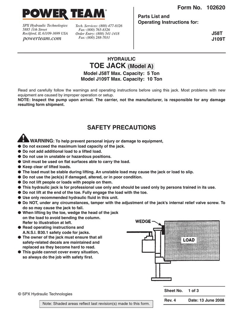
SPX Power Team J24T User manual

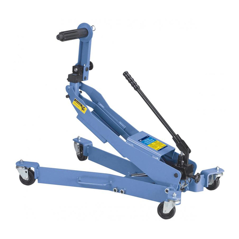
HYDRAULIC TOE JACK
Part Number J24T Maximum Capacity: 2 Ton
Part Number J55T Maximum Capacity: 5 Ton
Part Number J106T Maximum Capacity: 10 Ton
Read and carefully follow the warnings and operating instructions before using this jack. Most problems with new
equipment are caused by improper operation or setup.
NOTE: Inspect the jack upon arrival. The carrier, not the manufacturer, is responsible for any damage
resulting from shipment.
SAFETY PRECAUTIONS
WWAARRNNIINNGG::To help prevent personal injury or damage to equipment,
•Do not exceed the maximum load capacity of the jack.
•Do not add additional load to a lifted load.
•Do not use in unstable or hazardous positions.
•Unit must be used on flat surfaces able to carry the load.
•Keep clear of lifted loads.
•The load must be stable during lifing. An unstable load may cause the jack or load to slip.
•Do not use the jack(s) if damaged, altered, or in poor condition.
•Do not lift people or loads with people on them.
•This hydraulic jack is for professional use only and should be used only by persons trained in its use.
•Do not lift at the end of the toe. Fully engage the load with the toe.
•Use only Power Team hydraulic fluid in this unit.
•Do NOT, under any circumstances, tamper with the adjustment of the jack's internal relief valve screw. To
do so may cause the jack to fail.
•Read operating instructions and A.N.S.I. B30.1 safety code for jacks.
•The owner of the jack must ensure that all safety-related decals are maintained and replaced as they
become hard to read.
•This guide cannot cover every situation, so always do the job with safety first.
Form No. 102947
Parts List and
Operating Instructions
for:
J24T
J55T
J106T
Sheet No. 1 of 5
Rev. 2 Date: 28 Dec. 1998
© SPX Corporation
Tech. Services: (800) 477-8326
Fax: (800) 765-8326
Order Entry: (800) 541-1418
Fax: (800) 288-7031
SPX Corporation
5885 11th Street
Rockford, IL 61109-3699 USA
Internet Address:
http://www.powerteam.com
®

Parts List and Operating Instructions, Form No. 102947, Back sheet 1 of 5
OPERATING INSTRUCTIONS
IMPORTANT: Do not carry the jack by the jacking lever.
Lifting a Load
1. Position the load on the toe of the jack.
WWAARRNNIINNGG::Do not lift a load on the end of the toe. Fully engage the load with the toe.
IMPORTANT: When lifting by the toe, wedge the head of the jack on the load to avoid bending the column.
2. Turn the release valve knob in a clockwise direction until it is snug.
3. Pump the jacking lever in an up and down motion.
Lowering a Load
1. Slowly loosen the release valve knob by turning it in a counterclockwise direction. The more the knob is loosened,
the faster the load will be lowered. To stop the jack from lowering a load, tighten the release valve knob by turning
it in a clockwise direction.
PREVENTIVE MAINTENANCE
IMPORTANT: The greatest single cause of failure in hydraulic units is dirt. Keep the jack clean and well
lubricated to prevent foreign matter from entering the system. If the jack has been exposed to rain, snow,
sand, or grit, it must be cleaned before it is used.
1. When the jack is not in use, keep the piston and pump rods fully retracted. Store the jack on its base and in a well
protected area where it will not be exposed to corrosive vapors, abrasive dust, or any other harmful elements.
2. Visually inspect the jack before each use. Take corrective action if any of the following problems are found:
a. Cracked or damaged housing e. Incorrectly functioning swivel heads or adjusting screws
b. Excessive wear, bending, or other damage f. Loose hardware
c. Leaking hydraulic fluid g. Modified or altered equipment
d. Scored or damaged piston rod

Parts List and Operating Instructions Form No. 102947
TROUBLE-SHOOTING GUIDE
Repair procedures must be performed in a dirt-free environment by qualified personnel who are familiar with this
equipment.
Sheet No. 2 of 5
Rev. 2 Date: 28 Dec. 1998
TROUBLE CAUSE SOLUTION
Erratic Action
Jack does not advance
Jack only extends partially
Jack advances slowly
Jack advances but doesn’t hold
pressure
Jack leaks oil
Jack will not retract or retracts
slowly
1. Air in system
2. Viscosity of oil too high
3. Internal leakage in cylinder
4. Cylinder sticking or binding
1. Release valve is open
2. Low/no oil in reservoir
3. Air-locked system
4. Load is above capacity of system
1. Reservoir is low on oil
2. Piston rod is binding
1. Pump not working correctly
2. Leaking seals
1. Cylinder seals are leaking
2. Pump check valve not working
correctly
3. Overload valve leaking or not
adjusted correctly
1. Worn or damaged seals
1. Release valve is closed
2. Cylinder damaged internally
3. Reservoir too full
1. With jack sitting on its base and
ram retracted, bleed air by
opening release valve. Pump for
10 seconds.
2. Change to lower viscosity oil.
3. Replace worn seals. Check for
excessive contamination or wear.
4. Check for dirt, gummy deposits,
or leaks. Check for misalign-
ment, worn parts, or defective
seals.
1. Close release valve
2. Fill with oil and bleed system
3. Bleed the system
4. Use correct equipment
1. Fill reservoir
2. Check for dirt, gummy deposits,
or leaks. Check for misalign-
ment, worn parts, or defective
seals.
1. Rework pump
2. Replace seals
1. Replace seals
2. Clean/replace check valve
3. Replace/adjust overload valve
1. Replace seals
1. Open release valve
2. Send jack to authorized service
center for repair
3. Drain oil to correct level

Parts List and Operating Instructions, Form No. 102947, Back sheet 2 of 5
PARTS LIST FOR 2 TON JACK (J24T)
18
17
32*
31*
16
15
14
13
22
23
33*
24
21
4
3
2
12
11
10
9
8
7
25*
5
28*
29*
30*
6
1
19
20
* = Parts marked with an asterisk (*)
are in Repair Kit No. J24T-26.

Parts List and Operating Instructions Form No. 102947
Sheet No. 3 of 5
Rev. 2 Date: 28 Dec. 1998
1J24T-1 1 Handle
2J24T-2 1 Snap Ring
3J24T-3 1 Handle Socket Assembly
4J24T-4 1 Pump Plunger Pin
5J24T-5 1 Pump Plunger
6J24T-6 1 Release Assembly
7J24T-7 1 Safety Valve Push Nut
8J24T-8 1 Safety Valve Plug
9J24T-9 1 Safety Valve Adjusting Screw
10 J24T-10 1 Safety Valve Spring
11 J24T-11 1 Safety Valve Ball Guide
12 J24T-12 1 Safety Valve Ball
13 J24T-13 1 Pump Stay Pin
14 J24T-14 1 Snap Ring
15 J24T-15 1 Ram Guide Ring Stopper
16 J24T-16 1 Ram Guide Ring
17 J24T-17 1 Ram Packing Guide
18 J24T-18 1 Ram
19 J24T-19 1 Bolt
20 J24T-20 1 Washer
21 J24T-21 1 Hanger
22 J24T-22 1 Snap Ring
23 J24T-23 1 Stuffing Ring
24 J24T-24 1 Stopper Ring
25 *J24T-25 1 Filler Plug
28 *J24T-28 1 Pump Backup Ring
29 *J24T-29 1 Pump Packing
30 *J24T-30 1 Release Packing
31 *J24T-31 1 Ram Packing
32 *J24T-32 1 Ram Backup Ring
33 *J24T-33 1 Cylinder Packing
PARTS INCLUDED BUT NOT SHOWN
421686 1 Decal
Part numbers marked with an asterisk (*) are contained in Repair Kit No. J24T-26.
Item Part No.
No. No. Req’d Description

Parts List and Operating Instructions, Form No. 102947, Back sheet 3 of 5
PARTS LIST FOR 5 TON JACK (J55T)
1
2
3
4
5
22
21
36*
35*
20
34
31*
32*
7
6
2
8
927*
15
15
16
16
17
17
33*
18
10
11 12 1314 30
19
26
37*
25
24
23
* = Parts marked with an asterisk (*)
are in Repair Kit No. J55T-28.

Parts List and Operating Instructions Form No. 102947
Sheet No. 4 of 5
Rev. 2 Date: 28 Dec. 1998
Item Part No.
No. No. Req’d Description
1J55T-1 1 Handle
2J55T-2 1 Snap Ring
3J55T-3 1 Handle Socket Assembly
4J55T-4 1 Pump Plunger Pin
5J55T-5 1 Pump Plunger
6J55T-6 1 Pump Stop A
7J55T-7 1 Pump Stay Pin
8J55T-8 1 Pump Base
9J55T-9 1 Pump Stop B
10 J55T-10 1 Safety Valve Ball
11 J55T-11 1 Safety Valve Ball Guide
12 J55T-12 1 Safety Valve Spring
13 J55T-13 1 Safety Valve Adjusting Screw
14 J55T-14 1 Safety Valve Plug
15 J55T-15 2 Valve Plug
16 J55T-16 2 Valve Spring
17 J55T-17 2 Valve Ball
18 J55T-18 1 Release Assembly
19 J55T-19 1 Return Spring
20 J55T-20 1 Ram Guide Ring
21 J55T-21 1 Ram Packing Retainer
22 J55T-22 1 Ram
23 J55T-23 1 Hanger
24 J55T-24 1 Snap Ring
25 J55T-25 1 Stuffing Ring
26 J55T-26 1 Stopper Ring
27 *J55T-27 1 Filler Plug
30 J55T-30 1 Push Nut
31 *J55T-31 1 Pump Backup Ring
32 *J55T-32 1 Pump Packing
33 *J55T-33 1 Release Packing
34 J55T-34 1 Ram Guide Ring Stopper
35 *J55T-35 1 Ram Packing
36 *J55T-36 1 Ram Backup Ring
37 *J55T-37 1 Cylinder Packing
PARTS INCLUDED BUT NOT SHOWN
421687 1 Decal
Part numbers marked with an asterisk (*) are contained in Repair Kit No. J55T-28.

Parts List and Operating Instructions, Form No. 102947, Back sheet 4 of 5
PARTS LIST FOR 10 TON JACK (J106T)
26 25
1
24
39*
38*
23
41
24
3
5
34*
35* 6
7
8
9
2
31*
15
15
16
16
17
17
18
36* 10
11121314 37
19
20
21
17
22
27
28
29
40*
30
* = Parts marked with an asterisk (*)
are in Repair Kit No. J106T-32.
Note: Shaded areas reflect last revision made to this form.

Parts List and Operating Instructions Form No. 102947
Sheet No. 5 of 5
Rev. 2 Date: 28 Dec. 1998
Item Part No.
No. No. Req’d Description
1J106T-1 1 Handle
2J106T-2 1 Snap Ring
3J106T-3 1 Handle Socket Assembly
4J106T-4 1 Pump Plunger Pin
5J106T-5 1 Pump Plunger
6J106T-6 1 Pump Stop A
7J106T-7 1 Pump Stay Pin
8J106T-8 1 Pump Base
9J106T-9 1 Pump Stop B
10 J106T-10 1 Safety Valve Ball
11 J106T-11 1 Safety Valve Ball Guide
12 J106T-12 1 Safety Valve Spring
13 J106T-13 1 Safety Valve Adjusting Screw
14 J106T-14 1 Safety Valve Plug
15 J106T-15 1 Valve Plug
16 J106T-16 1 Valve Spring
17 J106T-17 1 Valve Ball
18 J106T-18 1 Release Assembly
19 J106T-19 1 Return Spring
20 J106T-20 1 Ram Spring Stopper Ring
21 J106T-21 1 Ram Spring
22 J106T-22 1 Vertical Pin
23 J106T-23 1 Ram Guide Ring
24 J106T-24 1 Ram Packing Retainer
25 J106T-25 1 Horizontal Pin
26 J106T-26 1 Ram
27 J106T-27 1 Hanger
28 J106T-28 1 Snap Ring
29 J106T-29 1 Stuffing Ring
30 J106T-30 1 Stopper Ring
31 *J106T-31 1 Filler Plug
34 *J106T-34 1 Pump Backup Ring
35 *J106T-35 1 Pump Packing
36 *J106T-36 1 Release Packing
37 J106T-37 1 Push Nut
38 *J106T-38 1 Ram Packing
39 *J106T-39 1 Ram Backup Ring
40 *J106T-40 1 Cylinder Packing
41 *J106T-41 1 Ram Guide Ring Stopper
PARTS INCLUDED BUT NOT SHOWN
421688 1 Decal
Part numbers marked with an asterisk (*) are contained in Repair Kit No. J106T-32.
This manual suits for next models
2
Table of contents
Other SPX Jack manuals
Popular Jack manuals by other brands
ULTIMATE SPEED
ULTIMATE SPEED 322261 1901 Operation and safety notes
Clarke
Clarke STRONG-ARM CHDDWD Operation and maintenance instruction
Clarke
Clarke CTJ1800A Operation & maintenance instructions
Sealey
Sealey AS2500 instructions

U-Line
U-Line H-1545 quick start guide
Cattini Oleopneumatica
Cattini Oleopneumatica YAK 312 Operating and maintenance manual
Performance Tool
Performance Tool W1622 owner's manual
Omega Lift Equipment
Omega Lift Equipment 32105B Operating instructions & parts manual

Chicago Pneumatic
Chicago Pneumatic CP80020 Operator's manual
Napa
Napa 791-2230 A Operating manual & parts list
Pro-Lift
Pro-Lift F1650A owner's manual
Clarke
Clarke CTJ2000G manual
