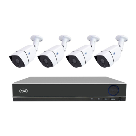
SpyCameraCCTV 1DIGLAN1003 User manual

1

2
Camera features
- IP65 rated
- Maximum wireless range: 100m (clear line of sight)
- 850nm infrared night vision LEDs - range up to 10m
- 9V, 600mA DC power supply for camera(s)
9” TFT LCD screen digital receiver features
- 800 x 480 pixel resolution
- Low power scan mode monitoring
- MicroSD card support. Maximum capacity supported: 64GB
- One LCD monitor can pair with up to four cameras
- Quad view display, up to 4 cameras simultaneously
- Maximum supported frame rates:
- 1 camera: 720p @ 15 fps
- 2 cameras: VGA @ 30 fps
- 4 cameras: VGA @ 15 fps
Recording modes:
- Manual
- Scheduled - per day of the week
- PIR motion detection
- Video motion detection
Alarm modes:
- PIR motion detection
- Video motion detection
- Individual recording les per camera
- 5 second pre-recording
- Two way audio - camera to screen / screen to camera
- Tour function
- Remote view and playback on Andoid and Apple iOS smart phones
- 5V, 2A DC power supply for LCD screen
FEATURE LIST
1DVRDIG1503

3
Feature List
1DVRDIG1503
This system includes the following components:
Wireless Monitor
Wireless Camera
Network Cable
AC Adaptor (9V) for camera
AC Adaptor (5V) for receiver
BOX CONTENT
1DVRDIG1503

4
Front Panel Buttons:
1.
2.
3.
4.
5.
6.
7.
8.
9.
10.
LCD Screen
Talk Back
Motion Recording
Manual Recording
Change Channel
Quad/Sequence Mode
Zoom
Delete File
Menu
Joystick
Displays video from the camera(s) or
displays system operations
Activate/Deactivate motion recording
Enable two-way audio intercom.
Activate/Deactivate manual recording
Switch between paired cameras
Switch between Tour and Quad (up to
4-channels) viewing mode
Switch between 2x digital zoom and
normal viewing mode
Delete highlighted les in Playback
mode
Open main menu. Return to previous
menu
Move left / right / up / down to move
the cursor in menus.
WIRELESS RECEIVER
1DVRDIG1503

5
Back Controls:
1. Fold Up Wireless Antennas: Position the antennas as needed for best
reception.
2. Power Button: Press and hold to turn the receiver on /
o. Single press while the unit is powered on to enable scan mode.
3. Receiver Stand
4. Speaker
5. UID Number and QR Code: Unique ID number for conguration on
smartphone and tablet.
6. Ethernet Port (RJ45): Connect the receiver to your router using the
included Ethernet cable to enable smartphone / tablet connectivity.
7. Power Port: Connect to a local power outlet using the included power
adapter.
8. Volume Controls: Turn the receiver volume up and down.
9. MicroSD Card Slot: Insert up to a 64GB MicroSD card.
10. USB Port: Used for service purposes only.
11. Reset: Using a paper-clip or other thin object, push the reset button to
restore the system to its default settings.
12. Power Indicator LED: Glows when receiver is connected to power.
WIRELESS RECEIVER
1DVRDIG1503

6
Wireless Camera:
1. IR LEDs – Infrared LEDs provide viewing in no/low light conditions
2. Camera Lens –Catches the video in front of the lens and transmits video
from camera to receiver.
3. PIR Sensor – Detects motion in front of the lens and transmits detection
signal to the LCD receiver.
4. Speaker – Produces the sound transmitted via talk-back button being
pressed on the LCD receiver.
5. Camera Antenna – For bi-directional communication with the LCD
receiver.
6. Wall Mounting Bracket – Use the bracket to mount the camera on a wall
or other at surfaces.
7. AC Adaptor Jack – Plug the power adaptor to the jack for camera’s
power supply.
8. Pair Button – The pair button is located on the back of the camera, it is
used to pair the camera with receiver.
WIRELESS CAMERA
1DVRDIG1503

7
Camera Installation:
Before you install the camera, carefully plan where and how it will be
positioned, and where you will route the cable that connects the camera to
the power adaptor.
Before starting permanent installation, verify its performance by observing
the image on the receiver when camera is positioned in the same
location/position where it will be permanently installed and the receiver is
placed in the location where it will be used most of the time.
Installation Warnings
Aim the camera(s) to best optimize the viewing area: Select a location for
the camera that provides a clear view of the area you want to monitor,
which is free from dust, and is not in line-of-sight to a strong light source or
direct sunlight.
Avoid installing the cameras where there are thick walls, or obstructions
between the Cameras and the Receiver.
Night Vision
This camera has built-in IR LEDs, which provides the camera with the ability
to view images in no/low light conditions.
WIRELESS CAMERA
1DVRDIG1503

8
Camera Installation:
Installing the Camera:
1. Carefully unpack the camera.
NOTE: If you are installing cameras that did not come with the system,
please see the pairing camera section of this manual for details on installa-
tion.
2. Mount the camera to the wall.
Mark the position of the screw holes on the wall, and drill holes and insert 3
screws, then rmly attach the camera to the wall. Make sure to strongly
secure the screw the mounting bracket into the wall
NOTE: The camera can also be placed on a at surface, such as a Table
or Shelf, and no mounting hardware is required.
3. Adjust the viewing angle of the camera. You can adjust camera angle to
desired viewing area.
NOTE: You can install additional cameras (maximum of 4 cameras).
When adding cameras that were not included in the original box, you
will need to pair up the cameras with the receiver. Refer to the camera
pairing section of this manual.
Connecting Camera Power:
The camera can be powered by using the provided power adaptor
Power Adaptor
Connect the power adaptor to the camera.
Make sure is the DC 9V for camera, and DC 5V for Receiver
Make sure the power adaptor is placed into a grounded outlet or surge bar
to protect the camera from power uctuations.
USING THE SYSTEM
1DVRDIG1503

9
Using the System:
By default, the camera(s) included with your system are automatically
paired to the receiver. The camera(s) and receiver will communicate with
each other once they are powered on. Note: it is recommended you power
on the cameras before powering on the receiver.
1.1 Understanding the On-screen Display
With camera 1 properly connected and powered on, the system displays a
full-screen live view of the camera.
With more than one camera properly connected and powered on, the
system displays up to 4 channels in split screen with the live view of each
camera. The gure below shows the display conguration for 2 cameras
connected.
USING THE SYSTEM
1DVRDIG1503

10
Using the System:
1. Signal Indicator –The signal indicator shows the strength of the signal
being received from the camera. The number of bars in the Signal Indicator
shows the strength of the signal. One, or no bars indicates the signal is poor,
and 4 bars indicate a very strong signal.
Note
• If the signal is low (e.g.,1 or 2 bars) adjust the antennas, or reposition the
cameras or receiver for best performance.
• The signal indicator does not shown while in Quad mode.
Signal Indicators:
USING THE SYSTEM
1DVRDIG1503

11
OUT OF RANGE Warning:
When the receiver can’t get signal from cameras, warning message will be
displayed. Reposition the camera, or check the camera power connection.
2 Channel Indicator – Displays the current channel number you are
presently viewing. If viewing multiple cameras at once, the camera
indicator will appear above each video display. Press Change channel to
switch between available cameras.
Note: In auto switch mode, press view to enter quad mode.
3 MicroSD Card Indicator – When a microSD card is inserted into the SD
card slot, the indicator will be shown on the LCD screen. A white icon shows
that a microSD card with available recording space is inserted in the
receiver. A red icon indicates the microSD card is full.
4 Network status Indicator –
A red icon shows that the connection has failed or the system is not
connected to a network.
A green icon shows that the system is connected to the Internet and is
accessible on your phone or tablet anywhere you have an internet
connection.
A yellow icon shows that the system is connected to your network, and will
only be accessible on phones and tablets in the same building as the LCD
receiver.
Remote connection Indication- When a smartphone / tablet is accessing the
system remotely, the network status indicator changes to a remote
connection icon
USING THE SYSTEM
1DVRDIG1503

12
OUT OF RANGE Warning:
5 Talk back Indicator- Touch and hold ( ) on the monitor then talk back
to the camera, the talk back indicator ( ) will be shown on the LCD
screen. You must be viewing a single camera for the talk-back function to
operate.
6 Recording Indicator–"RECUR" appears when recording is in progress. If
viewing and recording video from multiple cameras at once, the recording
indicator will appear above each video display where recording is enabled.
7 Zoom Indicator-Press the Zoom button on the front panel of monitor to
enter (×2) mode, the indicator will be shown on the LCD screen. When the
zoom icon ( ) shows on the screen, you can use the joystick buttons
( ) to navigate to parts of the video that are outside the range of
screen. Press zoom again to exit zoom mode.
8 Overwrite Indicator –Indicates Overwrite mode is on, which means the
system will overwrite the oldest recordings when the memory card is full.
When you choose the overwrite function, the indicator will be shown on
the LCD screen.
9 New Record Indicator- Indicates that there are new recordings saved to
the microSD card that you are yet to play back.
10 Battery Indicator- Indicates the battery life of LCD monitor in low
battery will show red and the green LED under the indicator light will ash.
11 Time stamp-The current date and time on the system (month/date/year,
hour/minute/second)
12 Motion recording indicator- Indicates that motion recording is turned
on.
13 Volume indicator-Shows the current volume of the receiver. You must
be in single channel viewing mode to change volume. The mute symbol
( ) indicates the volume 0.
14 New download icon -( ) appears on the screen if new rmware is
available.
USING THE SYSTEM
1DVRDIG1503

13
OUT OF RANGE Warning:
5 Talk back Indicator- Touch and hold ( ) on the monitor then talk back
to the camera, the talk back indicator ( ) will be shown on the LCD
screen. You must be viewing a single camera for the talk-back function to
operate.
6 Recording Indicator–"RECUR" appears when recording is in progress. If
viewing and recording video from multiple cameras at once, the recording
indicator will appear above each video display where recording is enabled.
7 Zoom Indicator-Press the Zoom button on the front panel of monitor to
enter (×2) mode, the indicator will be shown on the LCD screen. When the
zoom icon ( ) shows on the screen, you can use the joystick buttons
( ) to navigate to parts of the video that are outside the range of
screen. Press zoom again to exit zoom mode.
8 Overwrite Indicator –Indicates Overwrite mode is on, which means the
system will overwrite the oldest recordings when the memory card is full.
When you choose the overwrite function, the indicator will be shown on
the LCD screen.
9 New Record Indicator- Indicates that there are new recordings saved to
the microSD card that you are yet to play back.
10 Battery Indicator- Indicates the battery life of LCD monitor in low
battery will show red and the green LED under the indicator light will ash.
11 Time stamp-The current date and time on the system (month/date/year,
hour/minute/second)
12 Motion recording indicator- Indicates that motion recording is turned
on.
13 Volume indicator-Shows the current volume of the receiver. You must
be in single channel viewing mode to change volume. The mute symbol
( ) indicates the volume 0.
14 New download icon -( ) appears on the screen if new rmware is
available.
Viewing Modes:
There are four dierent viewing modes available on the system: single
channel viewing, Auto Sequence (Tour)
Viewing mode (view individual channels automatically in sequence), Quad
mode, and Scan mode.
Note: Auto Sequence Viewing mode cycles through connected channels in
full-screen. Use Quad mode to view up to four cameras simultaneously.
Use Scan mode, the receiver’s LCD screen and speaker will turn o unless
motion is detected by one of the cameras. The LCD screen turns on and
displays video from the camera where motion was detected for 15 seconds
before turning o again. This conserves battery power and alerts you only
when needed. You can congure how much motion is needed to turn the
display on in Scan mode by changing a camera’s video motion detection
settings. When exiting Scan mode, the receiver resumes live viewing in
Auto Sequence (Tour) Viewing mode.
To change viewing modes:
Press ( )view to select between Quad mode (half-Quad mode when only
2 cameras are connected) and Auto Sequence (Tour) viewing mode. OR
Press change channel icon to switch between channels 1-4 in single
channel view.
Quad Mode Half - Quad Mode
USING THE SYSTEM
1DVRDIG1503

14
MicroSD Card Recording:
The system records video to the microSD card (not included). You can
manually start or stop recording at any time by pressing the record button,
or enable motion record so the LCD receiver will automatically record only
when motion is detected by the camera, or schedule recording based on
the scheduled you set for each camera. Before recording, you need to insert
a microSD card to the microSD card slot. The system can support up to
64GB microSD card.
Recording Prerequisites: A microSD card must be inserted into the
receiver in order to record video. You should always format the microSD
card prior to initial recording.
The following recording modes are available on the system: manual
recording, schedule recording, and motion recording. Record up to 4
channels at the same time.
3.1 Motion Recording
System only records when motion is detected by a camera(s). Press Motion
( ) on the front panel of the receiver to start motion recording. There is a
red man ( ) on the bottom right of corner. In this mode the receiver starts
recording prior to 5 seconds when motion detected by any activated
camera. The recording time can be set to 15s, 30s or 1 minute after last
detection. (Receiver support recording 4 camera at the same time in quad
mode)
Press Motion again or press Rec to stop recording, after stopping recording
press Motion to cancel automatic recording mode.
USING THE SYSTEM
1DVRDIG1503

15
MicroSD Card Recording:
3.2 Manual Recording
Press ( ) Record on the front panel of the receiver to starts manual
recording. Press the key again to stop manual recording.
Note: In Quad view,it can continuous record from up to 4 cameras at a time.
3.3 Schedule Recording
Continuous or motion event recording from up to four cameras according
to a weekly schedule. Set the recording start time and end time, then
switch on schedule recording in the menu to enable schedule recording. In
this mode the receiver records at a certain time every day.
3.4 Overwrite
Enter recording menu—overwrite—choose “yes” to activate overwrite
function. Overwrite function can automatically delete previous records
when the micro SD card is full, and record new lms.
USING THE SYSTEM
1DVRDIG1503

16
Playback:
Playback mode allows you to playback recorded video les from the micro
SD card. You can view videos or images directly on the system or by
connecting the micro SD card to your computer.
4.1 Video Playback
To playback recorded video on the system:
1. During live viewing, click the joystick joystick, The Recording File List
opens.
2. Move the Joystick up / down to change the displayed month.
3. Select the channels you would like to view recordings from:
• Move the joystick left / right arrow to select the channel numbers
• Move the joystick up / down arrow to show or hide each channel on the
calendar.
• Select the button with all four channels to show recordings from all
connected cameras on the calendar.
4. Once you have selected the month and the channels to display on the
calendar, push the joystick to refresh the display. Dates that have recordings
available for playback are highlighted in green.
USING THE SYSTEM
1DVRDIG1503

17
Playback:
5. Move the joystick left / right to select a date on the calendar, and push
the joystick to view a list of recordings for that date.
Note:
• The system uses a 24-hour clock.
• Recordings are named by start time in hhmmss format and the channel
number (for example, the recording 133245-2 began recording at 1:32:45
PM on channel 2).
6. Select a le from the list and push the joystick to conrm then the
selected le loads and playback begins. Move the joystick left / right to
change pages to nd video les quickly. The selected le loads and
playback begins.
USING THE SYSTEM
1DVRDIG1503

18
Playback:
4.2 Playback controls:
1. Playback duration: Shows the length of the recording and how much has
been viewed.
2. File name
3. Playback status: Shows whether the video is playing, paused, or stopped.
To control playback using the joystick:
• LEFT: Rewind (2x > 4x > 8x > 16x).
• UP: Pause / Play video.
• RIGHT: Fast-forward (1x>2x > 4x > 8x > 16x).
• DOWN: Stop video.
• To change playback volume, press Volume Controls on the side of the
receiver.
To exit playback: Press ( ) Menu to return to the le list. Press ( )
Menu repeatedly to return to live view.
USING THE SYSTEM
1DVRDIG1503

19
Playback:
4.3 Deleting Video Files
You can delete les on the microSD card directly on the system. Delete les
if you need to clear space on the microSD card (if le overwrite is disabled),
or for your own le management purposes.
To delete les on the SD card:
1. From live viewing, press the joystick. The Recording File List opens.
2. Move the joystick up / down arrow to change the displayed month.
3. Move the joystick left / right arrow to select the channel numbers, and
move the joystick up /down arrow to show or hide each channel on the
calendar. Select the button with all four channels to show recordings from
all connected cameras on the calendar.
4. When you have selected the month and channels to display on the
calendar, push joystick to refresh the display. Dates that have recordings
available for playback are highlighted in green.
5. Move the joystick left / right arrow to select a date on the calendar, and
push the joystick to view recordings from that date.
6. Browse to the le you would like to delete. Press the green cross ( ) on
the front panel of the receiver.
7. A conrmation message appears. Select YES and push the joystick to
delete the le.
8. Repeat the steps above for other les on the microSD card.
USING THE SYSTEM
1DVRDIG1503

20
Playback:
CAUTION: Do NOT delete folders on the microSD card using your computer.
Deleting folders may aect your access to other les on the card or may
aect normal operation of the microSD card with the system. If you want to
delete the entire contents of the microSD card, it is highly recommended to
format the card using the system.
Viewing Video Directly from the microSD Card you can view the saved video
les on your computer (PC or Mac) by using a SD card reader (not included).
Saved video les are in ASF format.
Note: Some PCs and Macs may have a SD card reader built-in. Please refer to
your computer's instruction manual for more details.
You can view ASF les natively in Windows Media Player, as well as other
media players such as VLC.
VLC is an open-source software application available at www.videolan.org
To playback recorded video on a PC:
1. Remove the microSD card from the receiver by gently pushing on the
microSD card and then releasing. The card will eject.
2. Insert the microSD card into a SD card reader (not included) connected to
your PC. Your PC should load the microSD card as a new Removable Drive
and an Autorun window opens.
3. Click Open folder to view les or open the folder in Computer. Open the
folder MFG. You will then see a folder for each page of recorded video in
Playback mode. Folders are named by page number (e.g. recordings found
on the second page are in the folder 00000002).
4. Double-click any of the ASF les. The video will begin playing in your
default ASF media player.
USING THE SYSTEM
1DVRDIG1503
Table of contents
Other SpyCameraCCTV Security System manuals
