Sri 302 User manual

Model 302
Six Channel USB PeakSimple Data System
The Model302maybeusedwithanybrandormodelofGCorHPLCofferingananalog detector
outputsignal ranging from -5V to +5V. Itincludes three independent, programmable controls (0Vto+5V
analogoutput) for temperature & pressure or HPLCgradientformation. The Model 302 has six channels,
whichcanbe randomlyassigned tooneoffourtime bases,which allowsindependentstart andstop timesfor
fourseparateinstruments. Fourremotestartinputscompatiblewith2-wireswitchclosures(typicallyoutputby
GCsandHPLCs asa remotestartsignal) arealso includedforyour use. Twopulsestretchers areprovided to
accommodateintstrumentswithremote startsignalsshorter thanonesecond (suchasHewlett PackardGCs).
Thecomputertowhich youconnectthe Model302must supportUSB(it musthaveat leastoneUSB
port—rev2.0orhigher—and use WindowsTM 98, 98SE, ME, 2000, XP or newer).
The Model 302 comes in a sturdy
aluminumboxconsistingoftopandbottom
halves,secured together with two brass
thumbscrewsforeasy interioraccess.
The brass thumbscrews are on the left- and
right-handpanels ofthe Model302 box.
POWERIndicatorLED
Front View
With yourpurchaseof theModel302, youshouldreceive thefollowingitems:
1- Model 302 Data System box (front and rearviews shown below)
2- USB cable for connection to your computer’s USB port
3- Manual (either the PeakSimple Chromatography Data Systems or
theSRIgeneralproductmanual)
4-PeakSimple forWindowsTM software(insidethe manualcover)
Opening for analog signal cable(s)
andremotestartdeviceconnections POWER switch
USBconnector Powercord
Breaker
Rear View

2. Connect the Analog Signal Cable(s)
NOTE:The analog output fromsome GCs and LCs canhave a range of upto 10 volts DC. TheModel302
cantoleratethisvoltageinput,butsignalsabove6voltswillgenerateunwantednoiseandsignalsabove5volts
willbe “clipped”(the topsof the waveformswill becut off). Usethe 1 voltoutput typicallyavailable onthe
backofyourinstrument.
1. Open the Model 302
VerifythattheModel302ispoweredOFFandunplugged. Removethethumbscrews
on both sides of the Model 302 box and slide the top cover up and off. It is
connected to the bottom of the box by a ground wire, so just set it next to the
bottomhalfof thebox.
TheModel 302 box contains two circuit
boards. Theboard onthe right-handside
is the A/D board. The board on the left-
handsideundertheremovablehighvoltage
aluminumsafetycoveristhePowerSupply
board. Ifyouneed to remove thehigh
voltage aluminum safety cover,
ALWAYS unplug the Model 302 from
the wall power outlet first (you do not
need to remove it for the wiring
connectionsdescribedhere).
Highvoltage
aluminum
safetycover
Model 302
Six Channel USB PeakSimple Data System
PowerSupplyboard
A/Dboard
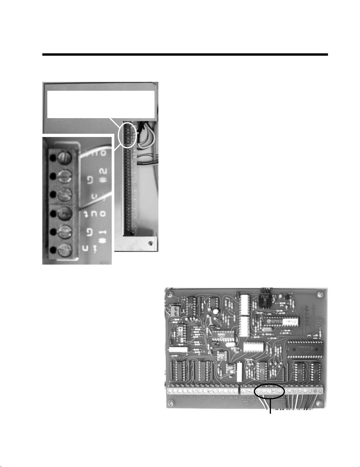
Channels1-6and GD(ground) screw terminals
2-1. Routetheanalogsignal cablesfromyourinstrument throughtheopenhole inthebackoftheModel302.
2-2. Strip 1/4” of insulation from the
“signal+” and “signal-” wires of your
instrument’ssignalcables.
2-3. Remove any jumpers placed in the
Channels1-6screw terminalsatthe factory.
Insertthe“signal+” wireintothe A/Dboard
screwterminalmarked “1+”and securethe
connection with a small flat-blade
screwdriver.
2-4. Insert the “signal-” wire into the A/D
board screw terminal marked “1 -” and
securetheconnection.
2-5. Repeatthe connectionof signalcables
for channels 2, 3, 4, 5, and 6. Any unused
channelsMUSThave bothinputsjumpered
toground.
3. Connect the Remote Start Cables (OPTIONAL)
TheModel 302 remotestart capability allows youto start the
datasystembymeansofaswitchclosure. Fourseparateremote
startcircuitspermittheusertoindividuallystartTIMEBASE1,
2, 3, and 4 of the data system. In some applications, the
chromatograph being used with the Model 302 may offer a
remotestartsignaloutputor switchclosureoutputthat permits
startingan integratoror otherdevice when theSTARTbutton
is pressed on the chromatograph’s on-board control panel.
Typically, this signal can be used to start the Model 302.
TIMBASES1 and 2 areequipped with pulse stretchers.
3-1. Routetheremotestartcablefromyourinstrumentthrough
theopen hole in the back of the Model 302.
3-2. Strip1/4”ofinsulationfromthe“+”and“-”wires ofyour
remotestart cable(s).
3-3. Insert the “+” wire into the Power Supply board screw
terminalmarked“#1IN”andsecuretheconnection.
3-4. Insert the “-” wire into the Power Supply board screw
terminalmarked“#1 G”and securethe connection.
3-5. Fora second instrument,insert the “+”wire into the “#2
IN”terminal,and the“-”wire intothe“#2 G”terminal.
3-6. The screw terminals for the third and
fourthinstruments’ remote startsare on the
A/Dboard. The bank of screwterminals is
labeled “DIGITAL IN” under “1 2 3 4.”
Connectthe“+”wiresforthethirdandfourth
instruments to screw terminals 3 and 4,
respectively. Connectboth “-” wiresto the
“GD”screw terminal next to the“4” screw
terminal(ontheright-handside).
NOTE: TIMBASES 3 and 4 require a
remotestartsignalthatpersistslongerforthan
one second. Check your instruments’
specifications(forexample,HewlettPackard
GCsproduceaveryshortremotestartpulse,
so you should connect one of these to
TIMEBASE1or2,whichareequippedwith
pulsestretchers).
Model 302
Six Channel USB PeakSimple Data System
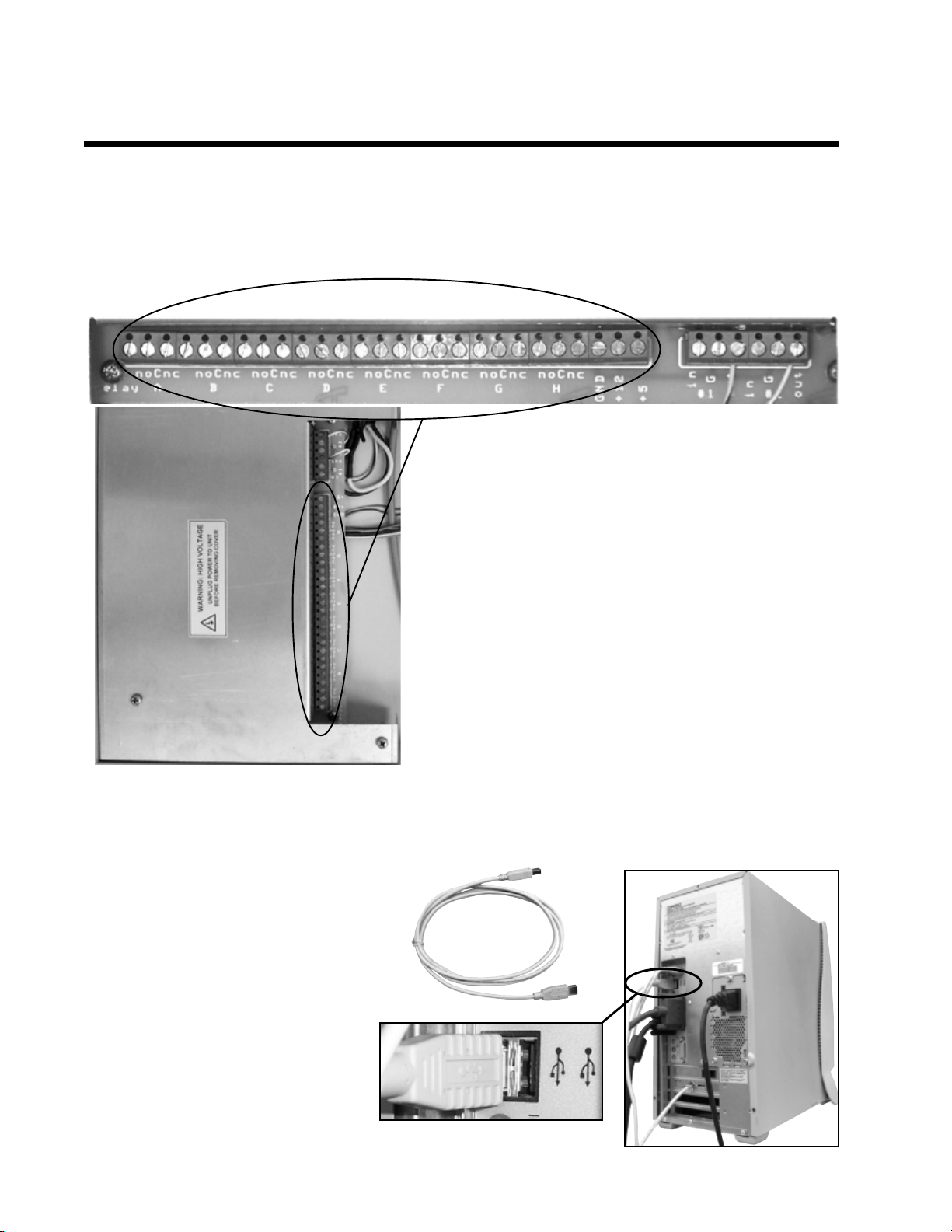
The remote start wires for the first two
instrumentsareinsertedintothesescrew
terminalson thePower Supply board.
Connectthe remote start “+” cablesto screwterminals “3” & “4,”
and the “-” cables to “GD”.
1234GD
Model 302
Six Channel USB PeakSimple Data System
4. Connect the External Event Relay Wires (OPTIONAL)
TheModel302 haseight 0-5volt TTLleveloutputsthatare wiredto abank ofmechanicalrelayswithscrew
terminalsfor easy connection to anydevicewhich may be operated from acontact closure (normally open
[NO]andnormallyclosed [NC]contactclosures). Theserelaysmaybeturned ONandOFFindividuallyand
automaticallythrough a PeakSimple timed event table. Manual control is also available via the computer
keyboard.
4-1. Routetheexternal eventwiresfrom yourinstrument
throughthe open holein the backof the model302.
4-2. Strip1/4” ofinsulation offof each wire.
4-3. Select which device should be connected to each
event (“A” through “H”), then insert the wire into the
appropriatescrew terminal on the Power Supply board,
andsecure the connection. Make and keep a listof each
device you connect and the Relay it is connected to for
yourreference(you willneed thisinformation toactivate
thedevicesautomaticallywith aneventtable ormanually
withthemouse).
Connectyour devices to theA-H Relay screw terminals
6. Connect the USB Cable to Your Computer
The Model 302 is equipped with a
USB connector. A USB cable
(provided) connects the Model 302
toyourWindowsTM computer’sUSB
port. This plug and play interface
permits the Model 302 to be loaded
ontoand operated from a desktop or
laptop computer that supports USB
(rev.2.0 orhigher).
6-1. SecureoneendoftheUSBcable
toanavailable USBport onyour PC.
6-2. Securetheotherend tothe USB
connector on the back of the Model
302.
5. Replace the cover on the Model 302 and secure it with the thumbscrews.
USBport
USBcable

7. Connect Power to the Model 302
The Model 302 is provided with a power cord which
plugsintoa standard 110(or 220) volt outlet. Plug the
Model302intothewalloutlet. TurnONthepowerswitch
andverifythatthePOWERLEDonthefrontoftheModel
302islit.
8. Install PeakSimple Chromatography Software
8-1. Locateyour copyof PeakSimple,which is shippedinside thefront
coverofyourmanual. InserttheCDorfloppydisk(s)intoyourcomputer’s
appropriatedrive.
Model 302
Six Channel USB PeakSimple Data System
The power LED is lit when the Model 302 is
connected to a power source & switched ON.
8-2. OpentheappropriatedrivethroughMyComputer,thendouble
clickon “Setup.exe” and follow the instructions. By default,the
setupprogramplacesthePeakSimpleapplication directoryonthe
hard drive: c:\peak2000. If you put the application directory
elsewhere, take note of the path as you may have to enter it in a
dialogboxduringtheUSB driverinstallationprocedure.
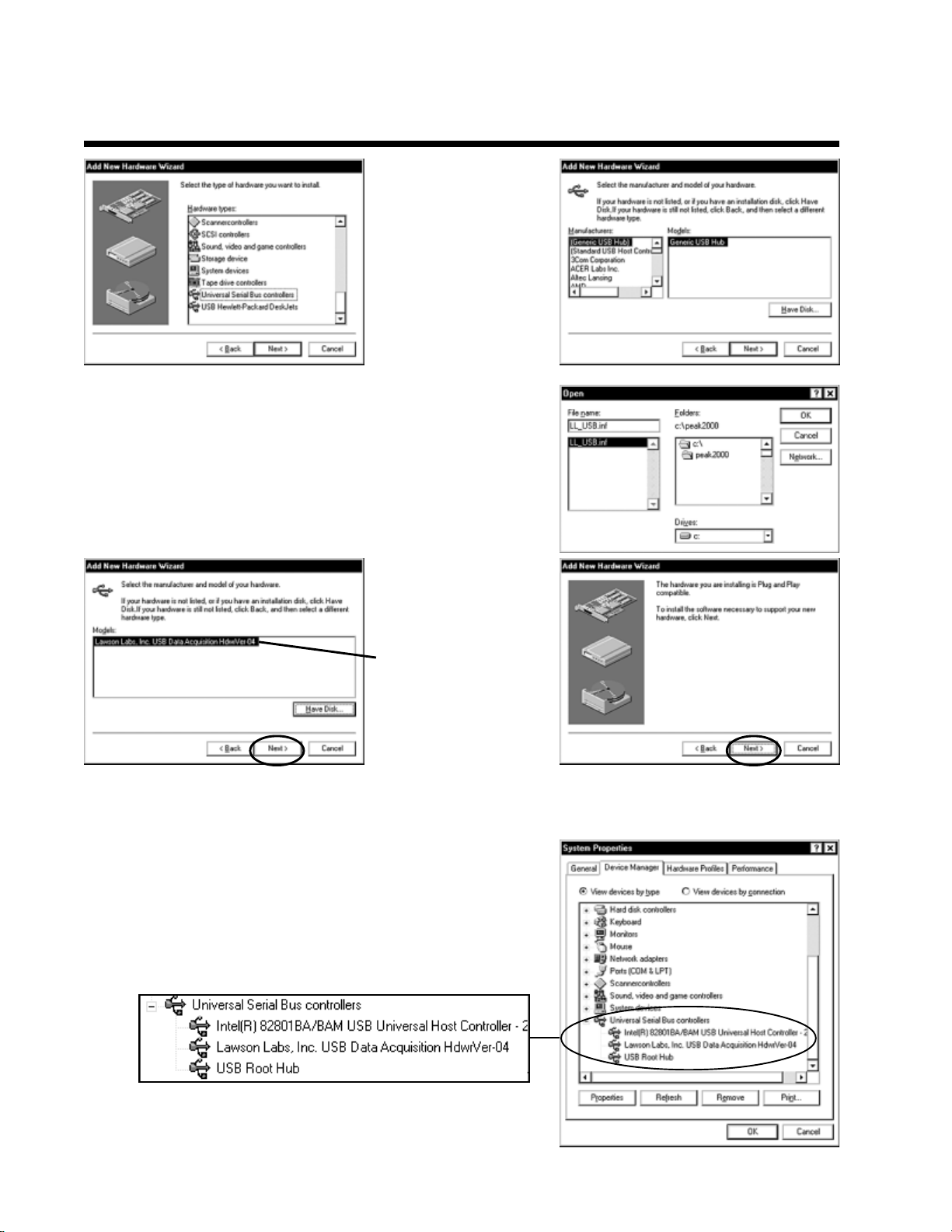
9. Install the USB Drivers
TherearethreeimportantfilessavedtothePeakSimpleapplication
directoryattheconclusionofthesoftwareinstallation:LL_USB.inf,
LL_USB.sys,andLL_USB2K.sys. These files are required for
WindowstorecognizetheA/Dboardconnectedtothecomputer’s
USBport.
9-1. Double-clickon theMy Computer iconon yourdesktop, then
on ControlPanel, then on Add New Hardware, which should open
theAdd NewHardwareWizard.
9-2. ClicktheNext button twice, until you get to the screen that
givesyouachoicebetweenlettingWindowsfindthenewhardware,
orselectingityourselffrom alist. Clicktheradio buttontochoose
thehardware fromalist andclick theNext button.
Model 302
Six Channel USB PeakSimple Data System
9-3. Scrolldown the
hardwarelist,clickon
Universal Serial Bus
controllers,then click
Next. From the
followingscreenclick
theHaveDisk button.
9-4. ClickBrowse and navigate to the PeakSimple application
directory, or type in the path (“c:\peak2000” or the name you
havechosen). TheWizardshouldfindtheLL_USB.inffile. When
youclick OK,theWizardwill verify that youwant to copyfiles
fromthe PeakSimple directory (“Copy manufacturer’s filesfrom:
c:\peak2000”).
9-5. When you click
OK again, the Wizard
will confirm that the
driversarefor Lawson
Labs. Click Next on
this screen and the
following screen, and
Windows will finish
installingthe software
for the Model 302.
ClickFinish.
9-6. Restart your computer (you MUST restart your computer
beforethe drivers willwork). Openthe ControlPanel again, then
System, then clickon the DeviceManager tab. Ifthe USB drivers
havebeensuccessfullyinstalled, theUniversalSerialBuscontrollers
section will list “Lawson Labs, Inc. USB Data Acquisition
HdwrVer-04.”
Model 302
Six Channel USB PeakSimple Data System
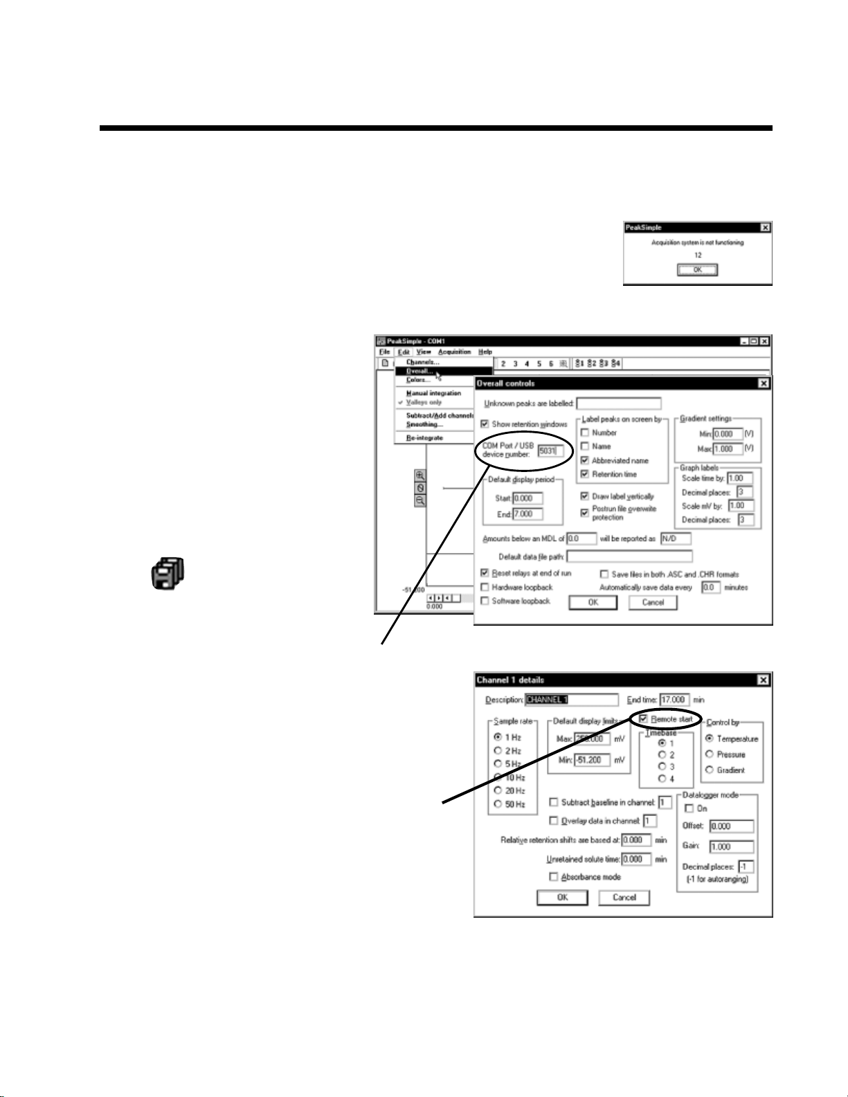
10. Launch PeakSimple
10-1. Double-click on the PeakSimple icon to launch the program. Verify that
communicationhasbeenestablished betweenyour computerand theModel 302.
Anerrormessage willappearifcommunicationisnotestablished. Thisisnormal
untilyoucompletethefollowingstep.
10-3. Fortheremotestartoption:
Open the Edit menu and choose Channels. Click on
the Details button for channel 1. Verify that Remote
startis enabled (the box should be checked). Repeat
thisstep forchannels 2-6if necessary.
10-4. ForinformationaboutusingEventtables,manualRelay activation,etc.,seethe“PeakSimpleTutorials”
andthe“PeakSimpleSoftware”sections inthemanual(andonlineatwww.srigc.com—clickonthe“Download
OurDocuments”button onthe homepage).
10-2. EachSRI USB datasystem has a
unique 4-digit USB device number
beginning with “5” (5031, 5032, etc.).
ThisI.D. number isprinted on the back
of your Model 302, and on your
PeakSimpledisk. OpenthePeakSimple
Edit menu and choose Overall. Enter
yourModel 302I.D. number inthe box
labeled“Comport/USBdevicenumber.”
ClickOK,andPeakSimple willattempt
to“wake-up”thedatasystem. Clickthe
SaveAll iconsoyou don’t have to
re-enterthe USBdevice number.
Enterthe4-digitUSB device numberhere

Technical Support:
Ifyouhavequestionsorproblems,callSRIforfreetechnicalsupport at310-214-5092,8am -5pmCalifornia
time.
11-2. Hit your computer keyboard spacebar to begin the run, and the data is plotted onscreen in the
chromatogramwindow.
11-3. Hit the End key on your computer keyboard to stop the run.
11. Starting an Analysis
10-1. TheupperrightcornerofthePeakSimplechromatogramwindowcontainsreal-timeinformationpertinent
toyouranalysisinprogress. The statusoftherun(STANDBY,RUN)is displayedincapitallettersnexttothe
millivolt(mV)reading,underneaththeamountoftimeintotherun.
Pressthe Endkey
to stop the run
Press the spacebar to begin the run
Model 302
Six Channel USB PeakSimple Data System
Other Sri Laboratory Equipment manuals


Popular Laboratory Equipment manuals by other brands


Heidolph
Heidolph MR Hei-Mix S operating manual

Leica BIOSYSTEMS
Leica BIOSYSTEMS Aperio GT 450 Administrator's guide

Fisher Scientific
Fisher Scientific Isotemp 600 Series Operation manual and parts list

Sigma
Sigma 10164 operating manual

Agilent Technologies
Agilent Technologies 7683 Service manual

Techne
Techne SBL-1 Operator's manual