Drawell GL10-MC Installation manual

Operation Manuals
High-Speed Refrigerated Centrifuge
Model: GL10-MC
Thanks for usingDRAWELL centrifuge! In order to get quick and sincere service,
please read the operation manuals carefully before you operate.

Contents
Contents................................................................................................................................... 1
Attention................................................................................................................................... 1
Attention for safety.................................................................................................................................. 1
Attention for fireproofing.........................................................................................................................2
Attention for safe operation................................................................................................................... 2
Attention for safety in chemistry and biology......................................................................................3
1. General introduction..............................................................................................5
1.1 Application and scope......................................................................................................................5
1.2 Name and Classify........................................................................................................................... 5
1.3. Centrifugation Theory..................................................................................................................... 5
2. Main technical parameters..............................................................................................5
2.1 Technical features............................................................................................................................ 5
2.2 Technical data................................................................................................................................... 6
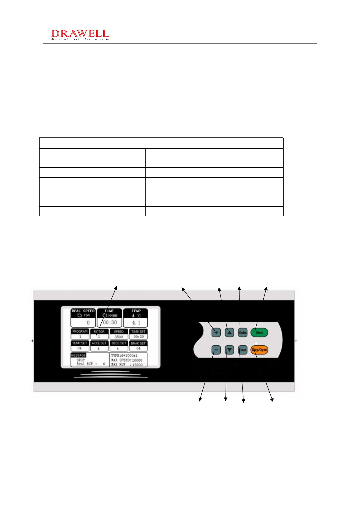
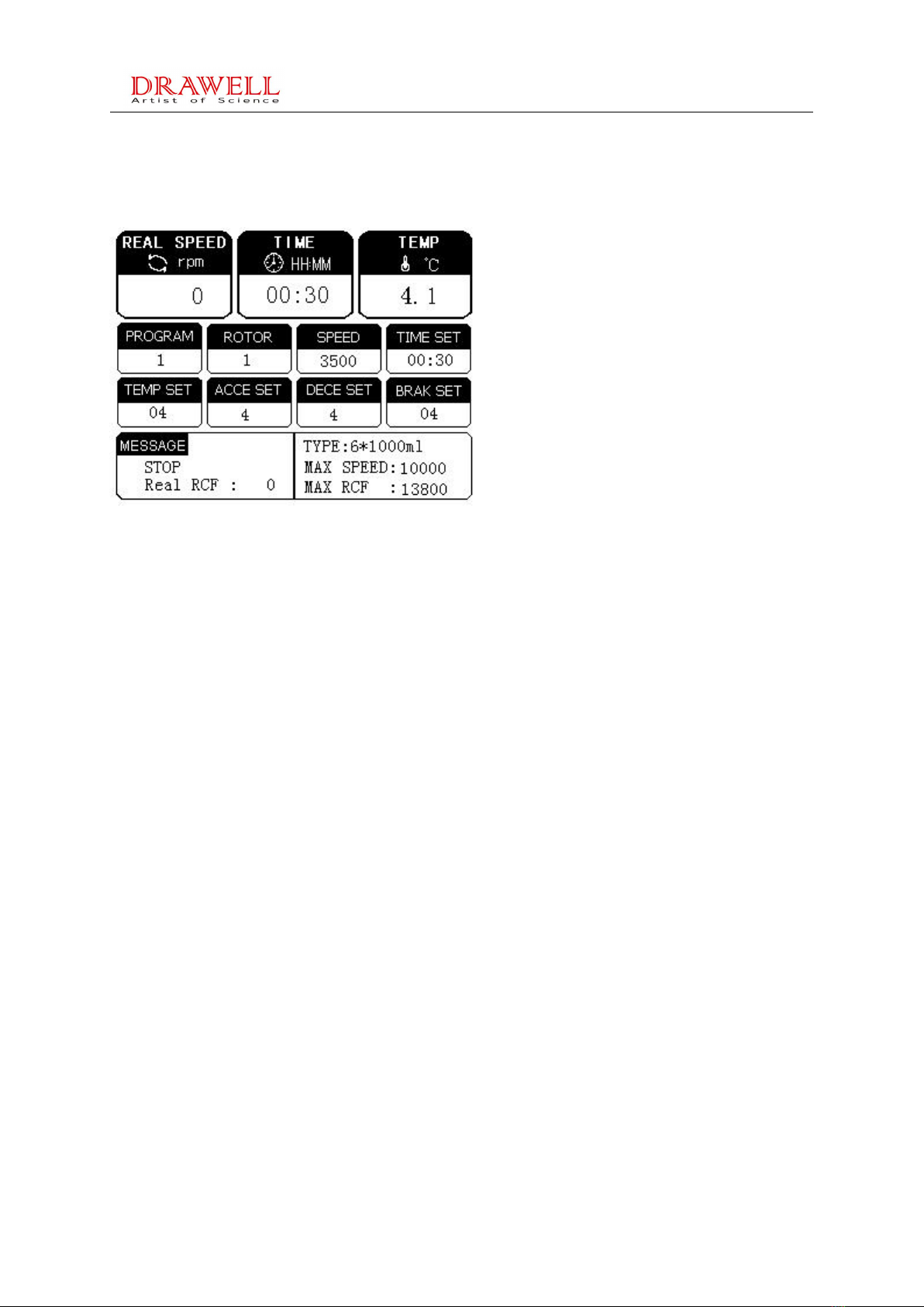
2.3 Control Display Panel...................................................................................................................... 6
3. Installation........................................................................................................................... 7
3.1 Installation Requirements............................................................................................................... 7
3.2 Normal Working Conditions.........................................................................................................7
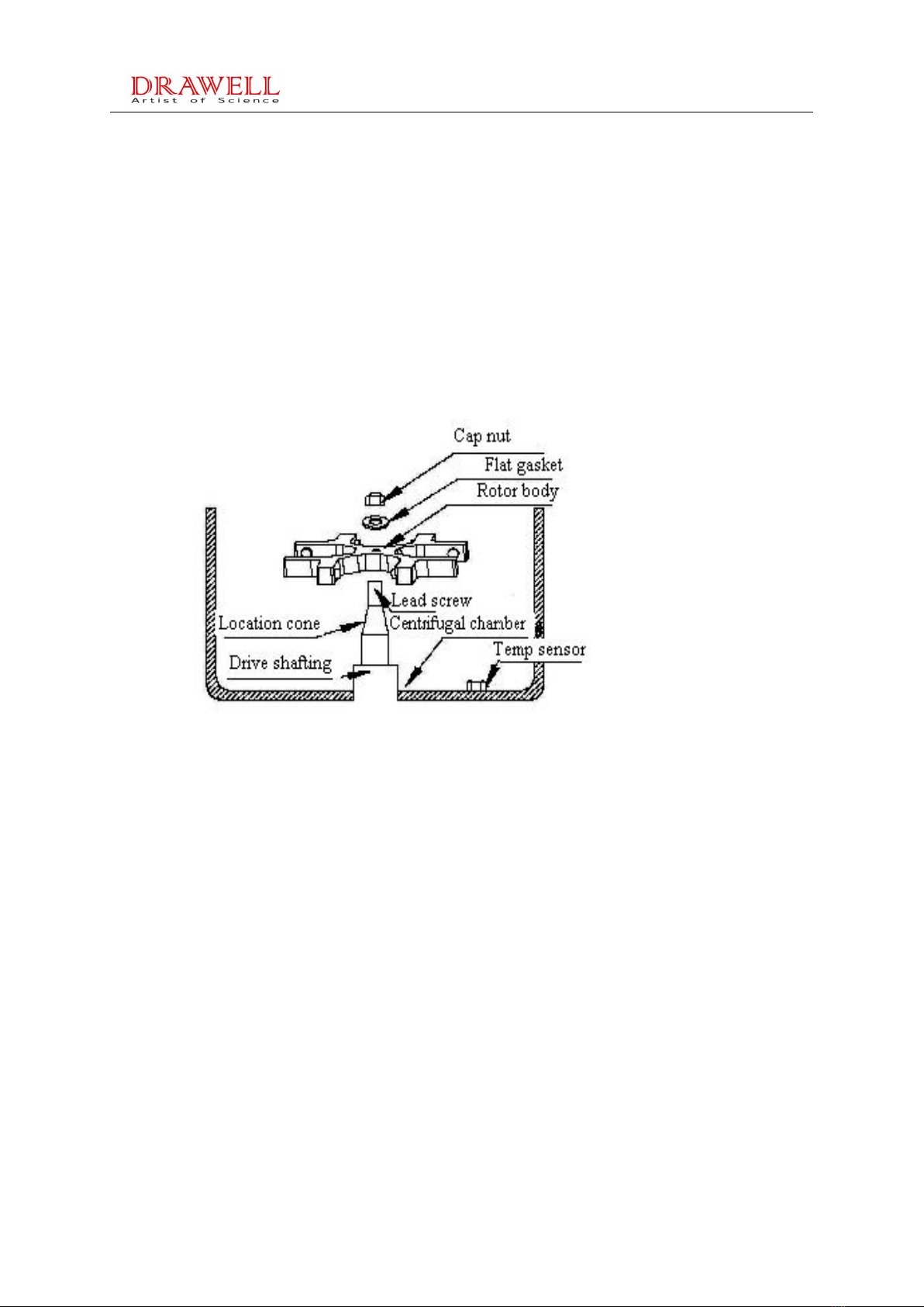
3.3 Rotor Installation............................................................................................................................8
3.4 Installation of Brackets and Tubes............................................................................................. 8
3.5 Operation Procedures & Directions...............................................................................................9
3.5.1 Power on................................................................................................................................ 9
3.5.2 Parameters setting................................................................................................................9
3.5.3 Closing the lid......................................................................................................................10
3.5.4 Start the machine................................................................................................................10
3.5.5 Stop the machine................................................................................................................10
3.5.6 Note....................................................................................................................................... 11
4. Maintenance......................................................................................................................11
5. Trouble Shooting............................................................................................................. 12
6. Instrument safety and protection................................................................................13
7. Electrical Block............................................................................................................. 14
8. Quality Warranty........................................................................................................... 14
Quality Certificate.....................................................................................................15
Packing List..............................................................................................................16
Warranty Card...........................................................................................................17
Service Records.......................................................................................................18
Service Manual.........................................................................................................19

1
Attention
Thanks for usingDRAWELL centrifuge, to prevent any potential accident,please operate the
centrifuge accortding to the following safty operation.
Attention for safety
Attention for safety clarifies the requirements of safe operation in the instruction
manual. Please carefully read it before installation, operation, maintenance and
repairing.Understanding the warning and correct operation can avoid the personal
injury and the damage of centrifuge.
Safety in installation and maintenance
The electricity should be cut off before repairing. Please take care if instrument
must be repaired with electricty on. Before opening any lids, please cut off the
electricity and wait for 4 mins.
Make sure for placing centrifuge on a steady floor or table and adjusting the level
for normal operation.
The power supply of centrifuge is the type of nameplate.If you have any problem
of the type of power,please consult the dealer and power supply bureau in your
place.
As safety measures, the centrifuge equipped with a single-phase three-wire
cable,and the longer cable connects with the casing as the protection grounding.If
your socket hasn't protection grounding,please contact your electrician to replace
the original socket without allowing security role of single-phase with three-wire
power cable to be invalid.
When replacing parts, the serviceman should use parts manufacturer required
with the same function of original parts. The unrecognized alternative parts may
cause fire, electric shock or other hazards.
The room should be installed an air-conditioner for good refrigerating effect when
temperature is higher than 35.℃
Please keep cleaning of the installation site for centrifuge. Pay attention to the
blockage of condenser, it should be cleaned once in three months for
guarantee the refrigerating effect.

2
Don’t unpack and repair instrument by oneself. Please contact with our
technicians for necessary matter.
Attention for fireproofing
Small breaker (air switch) can protect the circuit when centrifuge over-currents.
Please use the breaker (air switch) with same specification and model when
replacing it.
The centrifuge is not designed for the flammable and explosive matters. You
cannot make centrifugation for the matters (chloroform, acetaldehyde),and can
not put the matters in the centrifuge or store them around centrifuge within 30cm.
Attention for safe operation
Please use the rotor and accessories which are designed for this centrifuge.
Please check rotor, buckets and other accessories carefully before operation.
Input the right rotor number before operation for not exceeding of its max speed.
Attention: The max speed of rotor, buckets and accessories may be different.
Make sure that rotor can be installed on main spindly correctly for not damaging
the spindle part
Put all buckets (The same model) in rotor before operation for not exceeding its
max imbalance volume, close the rotor lid then.
Make sure if the centrifugal chamber is cleaned before operation.
Don’t reduce the speed by hand when it is rotating.
Don’t open door lid when rotor is rotating.
Don’t move centrifuge lid when rotor is rotating.
Anything is notallowed to enter into centrifuge during operation.
If tube is broken in centrifugal chamber, please clean out the fragments before
next operation.
If there is water condensing in centrifugal chamber, pleas wipe up it with clean
cloth.
The container with liquid should not be put around centrifuge; the electric parts
may be damaged for water spraying in.

3
If centrifuge is irradiated by ultraviolet radiation for long time, the outer skin may
be faded. Clothing should be covered for avoiding irradiation.
This centrifuge must not be used to separate the sample which producing
lammable and explosive gas. The stock around centrifuge is also forbidden.
Check rotor and buckets carefully before installation. It is forbidden to use the
cracked rotor and buckets, otherwise user should answer for all consequence.
It is forbidden to operate the rotor exceed of its max speed. If user has not set
rotor type according with the number on rotor lid, all damages caused by above
misoperation should be borne by user.
Please wipe up the rotor with neutral cleaning mixture after taking out for avoiding
corrosion and then stock it at dry, ventilated place. Central hole in rotor should be
smeared some lubricating grease for protection.
All action on rotor should be soft, and rotor should be taken out vertically for
protecting the shaft.
Please wipe up the water in centrifugal chamber if it is leaving unused. Some
lubricating grease should be smeared on drive shaft for protection.
The interval of between two operations is no less than 5 minutes for avoiding
damage of compressor.
If rotor damage occurring, allowable space to move for centrifuge is 30cm.
Anything should not be put around centrifuge within 30cm, especially for
flammable and explosive matter.It is not allowed to lean on the centrifuge when it
is running.Non-staff are not allowed to stay in the operation area.
When unpacking rotor and replacing rotor accessory and sample under low
temperature, the operator must adopt protection actions for avoiding tissue
frostbiting.
Centrifuge must be stopped when any abnormal phenomena occurring or error
code displaying, then you should inform our company or service agent soon.
Attention for safety in chemistry and biology
The routine manipulation may include all kinds of liquid and test sample which

4
may be the disease-causing and poisonous matters. The centrifuge can not be
manipulated with the matters unless you have toke the protection measures.
Please pay attention to the liquid explanation in container before operation.
Be careful of the infectious liquid. If not understanding the provided sample,
please at least make sure that they aren’t microbe. You must make further
aerosol,protection
(the suspended speck in the air, such as smoke and fog.) for the easier
disease-causing hepatitis virus(B or C), HIV, atypical mycobacteria and the
fungus of physical structure.
The infectious samples must be manipulated according to the manipulating
program and method in lab for avoiding expanding disease.
The spilt matters may produce aerosol(the suspended speck in the air, such as
smoke and fog.), so please pay attention to the warning about aerosol (the
suspended speck in the air,such as smoke and fog.)
Only use the suitable rotor and adaptor. The centrifuge can not be manipulated
with disease-causing, poisonous or radioactive matters unless you have toke the
protection measures. When the second type of hazardous substances (according
to “Laboratory Biosafety Manual” of the World Health Organization.) is
manipulated, the air safety level must be monitored. The superior substances
require a higher level of safe protection measurements. You should follow the
environment security and protection requirements when destroying the discarded
liquid.
Users have the responsibility to clean and sterilize centrifuge and accessory if you
need maintenance service from our company.
In a word, centrifuge is the high-risk common equipment in the lab which
refers to safety of people. Correct operation can avoid and reduce accidents.

5
1. General introduction
1.1 Application and scope
The centrifuge makes use of centrifugal theory to separate, purify and condense
various mixture liquid or emulsion with tiny particle and similar density.It can be widely
used in the fields of blood separation, pharmacy, biochemistry, genetic engineering
and radioimmunogy ets. It is ideal equipment for scientific research institutes, blood
bank, pharmacy manufactures and hospitals.
The model centrifuge has function of large RCF and capacity, it is the commen
equipment of centrifugal and manufacturer.
The machine adopt AC motor drive, frequency motor , micro control, light touch type
key and digital display panel , is a new generation models.
1.2 Name and Classify
Low-Speed Refrigerated Cebtrifuge .
It belongs to Class1 of medical laboratory equipmet accroding to the management
of " The Classified Catalogue of Medical Devices"
It belongs to the Class 1 of ordinary equipement with protection grounding
according to the protection against electric shok.
1.3. Centrifugation Theory
Centrifuge maks use of ther strong RCF that centrige rotates with high speed in
order to accelerate the setting speed of the granule in the liquid, and separate,
condense and purify the matters with different seetling coefficient and density.
2. Main technical parameters
2.1 Technical features
centrifuge, equipped with brushless motor, computer controller, door safety device
etc. for simple operation, is widely used in the fields of biochemistry, radio immunity,
environment protection.

6
2.2 Technical data
1. Max. Speed: 10000r/min 2. Max Capacity: 6×1000ml
3. Max. RCF(field): 13800xg 4. Time Range: 0~23h99min
5. Noise: ≤65dB 6. Temp Range: -20℃~+40℃
7. Speed control accuracy±50 r/min 8. Ac/Dc Rte: 0-9 Grade
9. Program storage capacity: 35
Rotor data
Rotor:According to the customer's request to process various rotor
Number
Max
Speed
Max RCF
Capacity
NO.1 Angle Rotor
4000r/min
13800xg
6×300ml
NO.2 Angle Rotor
4000r/min
11620xg
6×500ml
NO.3 Angle Rotor
4200r/min
12000xg
4×1000ml
NO.4 Angle Rotor
11500xg
6×1000ml
NO.5 Swing Rotor
4050xg
4×1000ml
Note :Speed and capacity can be customer designed
2.3 Control Display Panel
1 2 3 4 5
6 7 8 9

7
1). Display window:
2). Accelerate Key 3). Move up key 4). Confirm Key 5). Start Key
6). Decleration Key 7). Move down Key 8). Cancel Key 9). Stop/Open Key
3. Installation
3.1 Installation Requirements
a). The centrifuge should be placed on the firm table with four feet contacting the
table.
b). Certain space should be allowed around the centrifuge for idea ventilation
c). Power: AC 220V 50Hz 8.8A with socket capacity >10A,
ground connection should
be secured.
3.2 Normal Working Conditions
a). Environment temperature: 5℃~35℃
b). Relative Humidity: ≤85%
c). The centrifuge operating room should be free from Conductive dust,explosive or
corrosive gas
d). Power: AC 220V±22V50Hz±1Hz,and separate ground connection should be
provided in the centrifuge operating room

8
3.3 Rotor Installation
First clasp the spoke of rotor with one hand, and put the solid wrench on the cap
nut by another hand. In the mean while turn the wrench for 3 to 6 rounds in
counterclockwise direction to loose the cap nut until the rotor can be separated from
driving shaft. If the rotor is not taken out from the drive shaft for a long time and
blocked, you can beat the surrounding spoke of rotor several times slightly with
wooden or rubber hammer. Then clasp the symmetric spoke of rotor and lift slightly by
both hands, and put the rotor on the flat table and ground covered with soft pad.
The drive spindle in the chamber and the inside cones of rotor should be first
wiped with a piece of soft and clean cloth, then place the rotor with two hands to the
cone side of the drive spindle in the centrifuge chamber, Washer should be placed
before tightening the screw nuts.
Warning: The conical surface of rotor and drving shaft must connected tightly
3.4 Installation of Brackets and Tubes
Place the brackets into the slot of rotor; make sure that the bracket is turning smoothly,
tube sets(adaptors) are placed into holes of brackets, the solution to be separated
into the tubes. Visually check if the solution in the tubes is roughly equal before putting
them into the tube sets

9
3.5 Operation Procedures & Directions
3.5.1 Power on
Power switch is located on the right bottom corner of control panel. Turn it to “On”
position, the power indicator will turn red.
3.5.2 Parameters setting
1). After power on, the cooling system starts to work, now wait for 30 minutes for
pre-cooling.
2). 30 minutes later, set the appropriate program group, rotor number, speed,
temperature, time, acceleration and deceleration.
①Temperature setting: press▲or▼button, the temperature display window is a
digital flashing, adjust "+" or "-" buttons on the control panel to the desired conditions,
press the "confirm" button to confirm and save the parameters. When the centrifugal
chamber cooling for a certain time, the temperature display window shows the actual
temperature of centrifugal indoor.
②Rotor ID setting: press▲or▼ button,the Rotor display window is a digital flashing,
adjust "+" or "-" buttons to choose the corresponding rotor, press the "confirm" button
to confirm.
③Speed & RCF setting: press▲or▼button,the Speed display is a digital flashing,
adjust "+" or "-" buttons to the desired value, press the "confirm" button to confirm.
Press▲or▼button,the “RCF” display window is a digital flashing, press left or right
selection key , and "+" or "-" buttons to set the desired value, press the "confirm"
button to confirm. Please note the value of speed and rcf can not exceed the range.
④Time setting: press ▲ or ▼ button, the “Time” display window is a digital flashing,
press left or right selection key , and "+" or "-" buttons to set the desired value, press
the "confirm" button to confirm.
⑤Acc setting: press ▲or ▼ button,the “Acc” display window is a digital flashing,
adjust "+" or "-" buttons to the desired grade, press the "confirm" button to confirm.
10 kinds of acceleration, from 0-9, step 0 means speed up in the shortest time (e.g:

10
from 0-10000rpm), and step 9 is the lowest in speed up. When using the angle rotor is
heavy, or using swing rotor, pls choose a slower grade, like 5-6. You are suggested to
choose step 3 or 4.
⑥Dec setting: press ▲ or ▼button,
the Dec display window is a digital flashing, adjust
"+" or "-" buttons to the desired grade, press the "confirm" button to confirm.
10 kinds of deceleration, from 0-9, step 0 means slow down in the fastest time((e.g:
from 21000-0rpm), and step 9 is the lowest. In order to avoid damage to the
instrument or separation unclear, you are suggested to choose step 3 or 4.
3.5.3 Closing the lid
After finished the parameters setting, close the centrifuge lid. If “E-2” appears on the
“Speed screen”, it means the lid is not shut properly.
3.5.4 Start the machine
Press the "Start" button after all the parameters set over, then the indicator will light.
The program group, rotor number can not be changed in the operation of the
centrifuge. You can only modify the running temperature, time and speed.
Speed display window shows the actual speed of the rotor. Temperature display
window shows the actual temperature of the indoor centrifuge. The time on the time
display window decreasing.
The parameters can not be reset when the machine is running.
3.5.5 Stop the machine
when the time gets to "0" or press the "Stop" button, the buzzer gives an alarm and
stopping light works. The speed starts to decline. When it gets to "0r/min",it means the
machine stops. Meanwhile, buzzer will be alarming for 30 seconds (with pressing any
keys, the alarming will be gone) . At this time, the door of centrifuge can be opened,
and you can get out of the sample.
The next centrifugation, if without changing the settings, just press the start button
directly; if need to change settings, reset all the parameters as the same step.

11
when the speed display window does not show "0",pressing "open" key is invalid.
3.5.6 Note
1. The speed window shows the speed in running, but if you need to know the RCF,
just perss ▲or ▼transfer to RCF , then the “Speed” display window will be a digital
flashing, shows the RCF, press the "confirm" button to back to the speed display.
The same way if the window shows RCF but you need to know the speed when
running.
2. If you have different separation needs, we advise you to select different program
group to save your different parameters. First, set the parameters as above step, then
press button, Temp display shows P-X, press button to choose some program number
from 0~9,and now press"confirm" button to store the program number.
4. Maintenance
This machine has been designed to minimize the complexity of taking into account the
maintenance and inspection.
1). Maintenance of the centrifuge chamber
After the centrifugal test, do heating of the cream of the centrifuge chamber, and then
dry with a clean cotton cloth. If the rotor wont be used for a while, put the dry silica gel
bags into centrifuge chamber to absorb moisture and prevent shaft system from rust .
2). Maintenance of the rotor
Rotor block can not bump. Do not damage the cone. Clean carefully rotor block and
rotor cone with soft cloth before the rotor put in and coated with a little Vaseline or
other grease medical.
3). Maintenance of the control box and work surface
Control box and work surfaces must be kept clean. Rotor centrifuge tube and other
tools of centrifuge may not be placed on the panel to prevent scratches. Control box
and work surface can be only used with a soft cloth and mild detergent.

12
5. Trouble Shooting
1). The rotor does not work.
a). If the power light is off, check if the fuse is burned out, whether the power contact is
good.
b). Whether the value set is correct.
c). Whether it is under thermal protection after a long time working.
2). Cooling effect is not good
a). The temperature in the centrifuge chamber is too high.
b). The centrifuge is too close to the wall.
c). Condenser heat sink is blocked by dust or condenser fan is not running.
d). Refrigeration system refrigerant leaks or is mixed with air. Cooling system is
blocked or broken.
e). The re-poured amount of refrigerant is too little or too much after repair or
refrigerant is not a match.
3). The vibration and noise of the centrifuge increases or sound abnormal.
a). Whether the ground is solid, and whether there are strong availability of source
effects.
b). Whether rotor balancing is destroyed.
c). Whether centrifuge tube is qualified for balance, placing is symmetrical.
d). Whether level did not adjust well, it is with uniform stress.
e). Whether shaft bending jumps too large.
f). In the centrifugal midway,the centrifuge tubes or 0-type seal ring broke.
4). The rotor can not be put into the rotor block reposefully.
Check rotor and rotor block if there are scars or dirty objects.
Whether transfer pin is out of shape.
5). The rotor can not be got out of rotor block.
a). With using the rotor handle screwing into center of the rotor screw,the rotor can be
removed.
b).The rotor block cone and the rotor cone coated with a little grease can easily

13
remove the rotor.
c). Do not run for a long time when there is no refrigeration.
6. Instrument safety and protection
This centrifuge has multiple protection functions and will Stop automatically while
trouble occurs. The error code will be displayed in the ‘SPEED/RCF’ window, then
press [Stop] for display clearance.
Imbalance protection:E-1
During a run, the system will be Stopped automatically since the high vibration caused
by imbalance exceeds extent value and displaying “E1”.
Over-speed protection:E-2
The system can not work when the Setting speed is over max speed. Or, the system
will be Stopped automatically for actual speed is excess of rotor max speed or the Set
up speed by 5000r/min. “E6” will be then displaying.
Door lid protection: E-3
Since the centrifuge runs at high speed, it will not run for the door lid opening. If
forcing the door lid open during a run, the system will be Stopped automatically and
“E3” will be then displaying.
Hall Error:E-4
Hall error (motor Hall sensors are not connected to the transposon)
Over-voltage(shut down) E-5
(DC voltage is too high, causing the rise due to large load speed too fast, or drive
damage.)
Over-Current (running) E-6
(motor power supply is too large, causing large loads due to excessive increases
the speed, or drive damage.)
Velocity-measuring protection:E-7
The centrifuge will not Stop when velocity-measuring system is broken, “E7” will
display.
Error manipulation:E-8
Before a run error occurs, the system can not work; during a run Set wrongly, the
Setup would be invalid. In stand-by mode press [Start] key, “E8”will be then
displaying while it can not Start.
Inverter trouble:E-9

14
While inverter has trouble, the system can not work and “E9” will be then displaying.
Rotor disassembly:(after finishing adjust or centrifuge)
First clasp the spoke of rotor with one hand, and put the solid wrench on the cap
nut by another hand. In the mean while turn the wrench for 3 to 6 rounds in
counterclockwise direction to loose the cap nut until the rotor can be separated from
driving shaft. If the rotor is not taken out from the drive shaft for a long time and
blocked, you can beat the surrounding spoke of rotor several times slightly with
wooden or rubber hammer. Then clasp the symmetric spoke of rotor and lift slightly by
both hands, and put the rotor on the flat table and ground covered with soft pad.
Warning:All actions on the rotor must be soft for avoiding the damage of driving
shafting.
Door lid opening
After installing the main machine, Check the connection of all connectors and fuses
first, and turn on the main switch then. When the screen displays “8.8 8.8.8.8.8.
8.8.8.8. 8.8.8. 8.”, the software inversion No“B dL5H d.C.F. 2.1”(B-frequency
conversion control, d.C.F.-temperature controlled by solenoid valve,2.1-software
inversion No.)will be showed. Pull the latch on door lid lock device by manually, and
the door lid gradually opens at the holding of gas springs polar and your hands.
rounds in clockwise direction until the rotor connects the drive shaft closely.
7. Electrical Block
8. Quality Warranty
The centrifuge is guaranteed for quality, replace three months after it is sold,
free of charge repairing and maintenance for one year after it leaves factory due to the

15
material defects or others caused by the factory. Accessories and technical service
are to be provided at any time.

16
Quality Certificate
Floortype High-Speed Refrigerated Centrifuge GL10-MC
Max speed:10000r/min
Max RCF:13800xg
Serial No:
It is certified that the centrifuge is passed quality inspection & test .

17
Packing List
for Floortype High-Speed Refrigerated Centrifuge GL10-MC
No
Description
Quantity
Remark
1
Centrifuge
1set
2
Rotor
1set
6*500ml
3
Certificate
1pc
√
4
Operation Instructions
1pc
√
5
Packing List
1pc
√
6
Others
7
8
9
10
Packed by:
Inspected by:
Date:

18
Warranty Card
Service Records
Date
Contents
Signature
Name & Model
Floortype High-Speed Refrigerated Centrifuge
GL10-MC
Specifications
6*1000ml
Date of Delivery
Address
Table of contents
Other Drawell Laboratory Equipment manuals

Drawell
Drawell DW-GI Series User manual

Drawell
Drawell TANK User manual

Drawell
Drawell DW-280A User manual

Drawell
Drawell LBI-175A-N User manual

Drawell
Drawell B Series User manual

Drawell
Drawell DW-ATN-300 User manual

Drawell
Drawell DW-T960 User manual

Drawell
Drawell ZNHW-500ML User manual

Drawell
Drawell DW-280D User manual

Drawell
Drawell TDD4-MC User manual