SSBC A163-1 User manual

INSTALLATION INSTRUCTIONS
REAR DISC BRAKE CONVERSION KIT A163-1
Chevrolet Cavalier & Pontiac Sunfire
______________________________________________________________________
Thank you for choosing STAINLESS STEEL BRAKES CORPORATION for your braking
needs. Pleases take the time to read and carefully follow these instructions to insure the ease of
your installation as well as the proper performance of the complete system.
Before beginning your installation, please verify you have received all the parts indicated on
the packing slip. If you believe anything to be missing or incorrect, please call our Customer Service
Department at 716-759-8666.
To assure your installation will go safely and smoothly, have the following items on hand to
assist you:
JACK & JACK STANDS WRENCH SET
LUG WRENCH MALLET
TORQUE WRENCH TUBE WRENCHES
SOCKET SET BRAKE FLUID
BRAKE CLEANER
Stainless Steel Brakes Corporation • 11470 Main Road • Clarence, NY 14031
Phone: (800) 448-7722 • (716) 759-8666 • Fax: (716) 759-8688
www.ssbrakes.com • info@ssbrakes.com
Revision 3 3/28/12
These kits use the following pads:
SSBC#: 1047
FMSI#: D-347

BEFORE INSTALLING, PLEASE LAY OUT ALL OF THE CONTENTS OF THIS KIT
AND THOROUGHLY READ THROUGH THIS INSTRUCTION MANUAL TO ENSURE
THAT YOU HAVE ALL OF THE PARTS NEEDED TO COMPLETE THE INSTALL!
IF YOU FIND YOU ARE MISSING ITEMS, PLEASE CONTACT SSBC IMMEDIATELY,
REGARDLESS OF WHAT DEALER YOU PURCHASED THIS KIT FROM.
IF YOU HAVE ANY QUESTIONS REGARDING MISSING ITEMS, WARRANTY CLAIMS,
DEFECTIVE ITEMS, OR SIMPLY INSTALLATION ISSUES, PLEASE CONTACT SSBC DIRECTLY.
TOLL FREE: 800-448-7722
M-F: 9AM-5PM EST

1
A163-1 Revision 3
TIP: BEFORE BEGINNING INSTALLATION, SPRAY ALL FITTINGS & FASTENERS WITH
PENETRATING OIL.
1. Drum Brake Removal.
a) Raise the car until the tires and wheels clear the floor and support the car on jack stands.
Remove the tires and wheel assemblies from the drum.
b) Pull the brake drums off the axle. If the brake drum will not come off easily, retract the shoes
by inserting a narrow screwdriver through the adjusting slot in the backing plate and back off
the adjusting screw.
c) Disconnect parking brake cable from the actuator and pull through the backing plate after
compressing the retaining clip.
d) Disconnect the rigid brake line from the back of the wheel cylinder. Always use a tube
wrench on brake lines so not to strip the tube nut. Disconnect the electrical plug from the
back of the hub.
e) Working through the large hole in the hub flange, remove the four torx head bolts that hold
the hub and backing plate to the axle.
f) Remove the hub and backing plate from the axle and separate the hub and backing plate.
2. Installation of Caliper Mounting Brackets.
a) The caliper mounting brackets will be sandwiched between the end of the axle and the
backside of the hubs.
b) Place the brackets on the axle pointing toward the rear of the car. The drivers side should be
around the one o’clock position and the passenger side around the eleven o’clock position.
c) Place the hub on the axle over the caliper mounting bracket and secure using the original
nuts and bolts torqued to 50 ft/lbs. Be sure to reconnect the plug for the ABS sensor.
3. Installation of Rotors and Calipers.
a) Slide the rotors onto the hubs and secure with two lugnuts.
b) The calipers come loaded with the pads in place and are ready for installation. The calipers
will be installed with the parking brake levers on top. The calipers will be bled through the
special bleeders in the banjo bolts and not through the bleeders located in the caliper
castings.
c) Slide the calipers into position over the rotors and place one of the 7/16” flat washers
provided between the caliper and mounting bracket at each of the bolt holes to center the
caliper. Secure the caliper with the bolts supplied and torque to 80 ft/lbs.
d) Turn the rotor by hand to be sure it spins freely and there is no interference.
4. Brake Lines.
a) Disconnect the original steel lines at the flex hose and remove them. Install the new shorter
steel lines and bend them to follow the path of the original lines. The new lines are much
shorter and will only reach part way to the caliper.
b) Connect the flex lines supplied to the caliper using the banjo bolts and copper washers
supplied. Torque to 20 - 30 ft/lbs.
c) Rotate the flex line behind the shock and connect it to the new steel line. Tighten using a
tube wrench.
5. Parking Brake Cables.
a) Remove the original brake cables by loosening the cables at the adjuster located in the
center of the axle.

2
A163-1 Revision 3
b) Install the new cables in the same locations as the originals.
c) Install the parking brake L-Brackets supplied onto the upper caliper mounting bolt on both
sides of the car. The long leg of the bracket will go against the main mounting bracket and
the cable will pass through the short leg. It may be necessary to trim the length of the long
leg so the bracket can be positioned correctly. Place one 7/16” flat washer under the long leg
of the L-Bracket when bolting it on so it sits flat against the main mounting bracket.
d) With the L-Bracket in place, route the cable through it and lock the cable into the lever on the
caliper.
e) Take the slack out of the cables at the adjuster on the axle. Be sure to re-adjust the cables
when the car is on the ground and the rear suspension is compressed as this will affect cable
adjustment. Always be sure the levers on the calipers return completely when the parking
brake is released or brake drag will occur.
6. Filling and Bleeding system.
a) It is advisable to replace the brake fluid if the color is brown or muddy. This is due to water
that has been absorbed by the fluid which will eventually corrode the brake lines
b) The simplest and most effective way to bleed your brakes is to use the gravity bleeding
approach as follows:
1) With calipers installed, make sure all fittings are tight and master cylinder is topped off.
2) Open one bleeder screw at a time starting at the wheel farthest from the master
cylinder and working your way back around the wheel closest to the master. With
bleeder screw open, observe bleeder. At first the fluid will begin to escape with
intermittent air bubbles. When the air bubbles stop and a steady flow of fluid is
observed for several seconds, close the bleeder valve and move on to the next wheel.
MAKE SURE TO KEEP A CLOSE WATCH OVER THE FLUID LEVEL INSIDE THE
MASTER CYLINDER DURING THE BLEEDING PROCESS. NEVER LET THE
RESERVOIR RUN DRY. ALWAYS KEEP IT AT LEAST 1/3 FULL.
3) After bleeding both wheels and topping of the master cylinder make 20-30 applications
of the brake pedal. If a hard pedal is experienced, no further bleeding is required. If
pedal is spongy, repeat bleeding process until a hard pedal is achieved.
4) With all bleeding complete, there should be approximately 3/4” to 1” of end play.
5) Power brake cars will experience a “drop off” of the pedal when the engine is started.
This is a normal condition that signifies the booster is working.
7. Final Inspection.
a) Once a hard pedal is achieved, all fittings and connections must be inspected to make sure
there are no leaks. Also check the level in both reservoirs of the master cylinder and top off if
needed.
b) Put wheels back on the car and turn wheel by hand to insure that the wheel spins freely and
does not interfere with any brake components.
c) When you are sure there are no interferences and the pedal is firm, torque the lug nuts and
lower the car back onto the ground. Test drive the car and apply the brakes frequently to
seat the pads.

3
A163-1 Revision 3
e) The rear brake pressure can be adjusted by turning the knob on the adjustable proportioning
valve. It should be adjusted so the rear brakes do not lock up before the fronts.
DO NOT USE ANTI-SQUEAK ADHESIVE ON BACKS OF PAD. THIS WILL
DEGRADE THE PERFORMANCE OF THE CALIPER!
DO NOT DRIVE IN TRAFFIC UNTIL THE BRAKES SAFELY STOP THE CAR A
SAFE DISTANCE WITHOUT A SPONGY PEDAL FEEL!
BRAKING TESTS SHOULD ALWAYS BE DONE IN A SAFE OPEN AREA!
NOTE: For frequently asked questions and technical reference information please visit
the tech section of our website at www.ssbrakes.com.
TECH LINE -- If technical help is required, please call 716-759-8666.
NOW ENJOY TRUE PERFORMANCE BRAKING!!
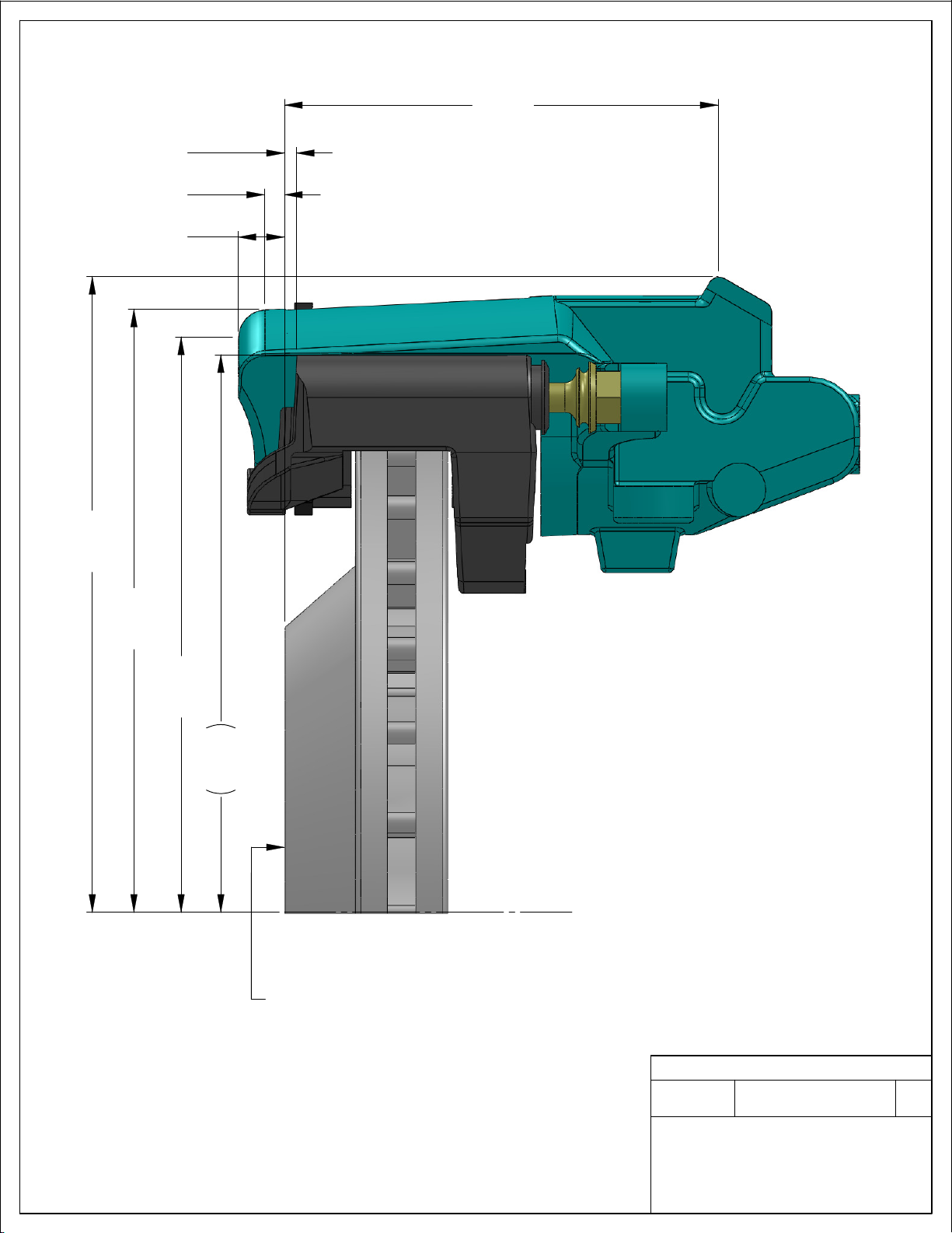
4.84
6.42
6.74
6.88
7.10
WHEEL MOUNTING SURFACE
C
L
.13
.52
.22
REV
DRAWING
Ph 716-759-8666 / 800-448-7722 ~ Fx 716-759-8688
T-040
WWW.SSBRAKES.COM
SSBC
-
TEMPLATE NO.
STAINLESS STEEL BRAKE CORP.
CLARENCE, NEW YORK 14031-1720
DO NOT SCALE
DIMENSIONS ARE IN INCHES
Table of contents
Other SSBC Automobile Accessories manuals


Popular Automobile Accessories manuals by other brands

Caraudio-Systems
Caraudio-Systems CI-RL4-MIB101 manual

NAV TOOL
NAV TOOL NAVRGB6.0-VI installation manual

Silvercrest
Silvercrest SBTF 10 C2 operating instructions

FormFit
FormFit 969 installation instructions

Silvercrest
Silvercrest SLAL 2 A1 Operation and safety notes

Air Lift
Air Lift Ride Control 591510 instructions


