SSBC W123-A User manual

INSTALLATION INSTRUCTIONS
PERFORMANCE AT THE WHEELS KITS
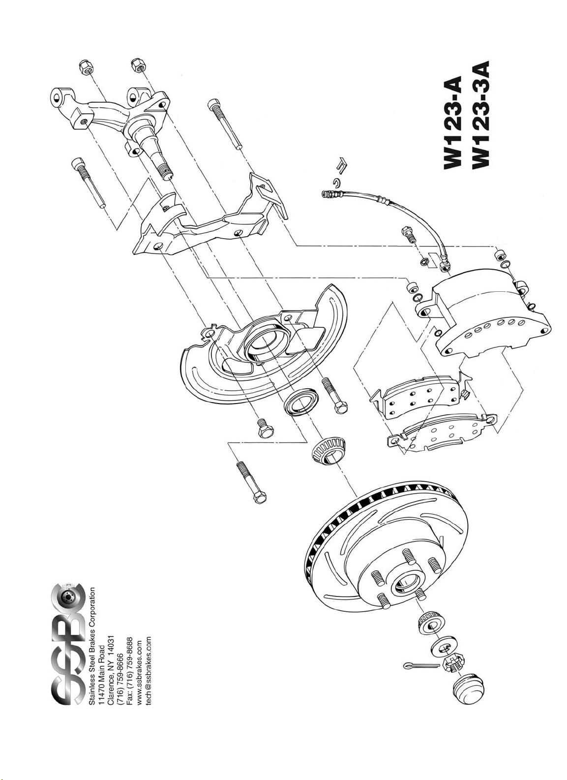
W123-A, W123-3A
1964 - 72 A-BODY
1967 - 69 F-BODY
1962 - 74 X-BODY
_____________________________________________________________________
Thank you for choosing STAINLESS STEEL BRAKES CORPORATION for your braking
needs. Please take the time to read and carefully follow these instructions to insure the ease of your
installation as well as the proper performance of the complete system.
Before beginning your installation, please verify you have received all the parts indicated on
the packing slip. If you believe anything to be missing or incorrect, please call our Customer Service
Department at 716-759-8666.
To assure your installation will go safely and smoothly, have the following items on hand to
assist you:
JACK & JACK STANDS WRENCH SET
LUG WRENCH TUBE WRENCHES
TORQUE WRENCH MALLET
SOCKET SET WHEEL BEARING GREASE
BRAKE CLEANER BRAKE FLUID
Stainless Steel Brakes Corporation • 11470 Main Road • Clarence, NY 14031
Phone: (800) 448-7722 • (716) 759-8666 • Fax: (716) 759-8688
These kits use the following pads:
SSBC#: 1015
FMSI#: D-52
Revision 3 3/7/12

BEFORE INSTALLING, PLEASE LAY OUT ALL OF THE CONTENTS OF THIS KIT
AND THOROUGHLY READ THROUGH THIS INSTRUCTION MANUAL TO ENSURE
THAT YOU HAVE ALL OF THE PARTS NEEDED TO COMPLETE THE INSTALL!
IF YOU FIND YOU ARE MISSING ITEMS, PLEASE CONTACT SSBC IMMEDIATELY,
REGARDLESS OF WHAT DEALER YOU PURCHASED THIS KIT FROM.
IF YOU HAVE ANY QUESTIONS REGARDING MISSING ITEMS, WARRANTY CLAIMS,
DEFECTIVE ITEMS, OR SIMPLY INSTALLATION ISSUES, PLEASE CONTACT SSBC DIRECTLY.
TOLL FREE: 800-448-7722
M-F: 9AM-5PM EST
1
W123-A, -3A Revision 3
1) Raise the vehicle until the wheels and tires clear the floor; support front of vehicle on jack
stands. Make sure parking brake is engaged. Remove front wheels and tire assemblies.
2) Remove spindle assembly:
a) Remove tie rod ends from spindle after removing retaining hardware. We strongly
recommend the use of a splitter "picklefork" for this purpose!
b) Remove both front shock absorbers.
c) Compress both front coil springs with appropriate spring compressor and remove from
car. The use of a safety chain around the control arms is recommended to prevent
sudden spring unloading during this operation.
d) Disconnect both upper and lower ball joints and remove spindle assemblies from car.
Separate ball joints from spindle.Remove hub from spindle, save for re-installation.
e) Retain all original hardware for possible reuse.
3) Install new spindle assembly:
a) Check ball joints prior to re-assembly and if any play is indicated, replace with new
parts.
SPINDLE BEARING SURFACES ARE PRECISION MACHINED, PROTECT
MACHINED SURFACES AGAINST DAMAGE.
BEFORE REINSTALLING STEERING ARMS, DRILL OUT FACTORY 7/16"
HOLES TO 1/2" HOLES TO ENABLE REATTACHMENT TO SPINDLE.
NOTE: WHEN INSTALLING KITS A123-3A OR A123-4A ON 1962-64 CHEVY II /
NOVA, 1965-67 V8 (5 LUG) STEERING ARMS WILL BE REQUIRED.
b) Install new spindles and ball joints. Make sure that steering arms point toward rear of
car. Torque lower ball joint to 65ft-lbs, upper ball joint to 50 ft-lbs.
WITH SOME CARS, IT WILL BE NECESSARY TO DRILL THE TWO STEERING
ARM HOLES OPEN TO 1/2”TO USE THE NEW NUTS AND BOLTS SUPPLIED.
c) Re-install coil springs in reverse manner of removal.
d) Re-install shock absorbers. Install curved steering arms onto new spindles as in the
reverse manner of removal. Note bolts are not the same length, rear bolts are 1/2”
longer.
e) Re-install tie-rod ends and castellated nuts, torque to 35 ft-lbs. install new cotter pins
4) Install caliper mounting brackets and hardware
a) Place caliper mounting bracket over spindle with ears facing outward, 5/8"dia hole on
top.
b) Place splash shield over bracket and secure both bracket and splash shield to spindle
with (1) 5/8"x 1" bolt and (2) 1/2"-20x2-1/2" bolts. Bend “tab-locks,” on splash shield
against 1 bolt flat.
c) Install new wheel bearings, after packing with a good grade of wheel bearing grease.
(Inner wheel bearings must first be installed in rotors and retained with provided
grease seals). Use large socket or seal installer tool for correct seating of grease seal.

2
W123-A, -3A Revision 3
BE CAREFUL THAT ALL HYDRAULIC COMPONENTS ARE KEPT CLEAN AND
FREE OF DEBRIS, INSIDE AND OUT. REMEMBER, DIRT IS THE ENEMY OF
HYDRAULIC SYSTEMS. SSBC WILL NOT BE RESPONSIBLE FOR SYSTEM
FAILURES DUE TO AN UNCLEAN INSTALLATION.
d) Install rotor over spindle and follow up with new outer bearing, retaining washer and
nut. (Turbo slotted rotors are available, contact SSBC or your distributor for more
information.)
e) Torque spindle nut to 12 ft/lbs. While turning rotor, loosen nut one flat and insert cotter
pin.
IF SLOT AND PIN HOLES DO NOT LINE UP, TURN NUT BACK ENOUGH TO
INSERT COTTER PIN. MAKE SURE THAT ROTOR SPINS FREELY!
f) Install grease cap, do not tap on the center, it will crush easily
5) Preparation and Installation of calipers
a) Prior to installing calipers, connect flex lines to calipers with hollow bolt and (2) copper
washers, one on top and one on the bottom. Don’t tighten bolt until after caliper is
mounted.
b) Install inboard brake pad with supplied support clips. Inboard pads must lay flat
against piston.
c) Install outboard brake pad in the caliper with the ears of the pad in the clearance holes
of the caliper and the bottom of the pads engaged in the recess of the caliper. It will be
necessary to bend the tabs on the top of the pad down to lock the outer pad into the
caliper. It may be necessary to take the pad in and out several times until the proper
amount to bend the tabs is found.
d) Lubricate supplied caliper mounting bolts with silicone grease or other non-petroleum
lubricant.
e) Position the caliper assembly over the rotor and line up the holes in the caliper ears with
the holes in the mounting bracket. (Bleeder screws must point up)
f) Install mounting bolts, making sure that the ends of the bolts pass under the retaining
ears on the inboard pad. Push bolts through to engage the bushings of the outboard
caliper ears while at the same time threading the bolts into the mounting bracket.
Torque bolts to 25-30 ft/lbs.
g) Temporarily connect free end of flex lines to the 12 point retainer brackets on the frame
and temporarily secure with "horseshoe clip”. Turn steering assembly through a full left to
right turn, while noting flex lines, to assure that they do not twist or take a double bend.
If incorrect, remove them from the 12 point bracket and re-orient the hose with minimum
distortion. Complete permanent connection using a tube wrench.
FAILURE TO COMPLETE THIS PART OF THE INSTALLATION MAY CAUSE
BRAKE LOCK-UP IN SERVICE. THE THIN WALL INTERIOR HOSE OF THE FLEX
LINE CAN COLLAPSE DURING TURNS AND RESTRICT THE FLUID FROM
RELIEVING THE CALIPER BRAKE LINE PRESSURE WHEN THE BRAKE PEDAL
IS RELEASED. MAKE SURE ROTOR SPINS FREELY AND THERE ARE NO
INTERFERENCES.

3
W123-A, -3A Revision 3
6) To insure the proper function of your SSBC brake system several other parts will be required to
complete the installation. If you did not purchase these parts at the same time as your brake kit
they can be ordered from SSBC or your distributor. If you choose to source your own parts
please keep the following points in mind.
a) Master Cylinder
A master cylinder designed for disc brake applications must be used. Be sure the depth
of the piston is correct for the pushrod length you are using. For manual brake
applications a bore size of 15/16”-1” is needed. For power applications a 1” bore size will
work correctly.
b) Power Booster
The vehicle must have a minimum of 16” of vacuum at idle for the booster to work
properly. If you do not have at least 16”Hg you will need a vacuum pump or you will have
to run a non power system. Be sure to select a booster for your specific year, make, and
model with the proper brackets and pushrod. For some vehicles you will have a choice of
the outside diameter of the booster. Generally speaking a larger outside diameter will
provide more boost than a smaller one. The only exceptions are double diaphragm
boosters. Keep in mind that your space for a booster will be limited by things like big
block engines and tall valve covers. SSBC generally recommends a 7”-9” diameter
booster for your vehicle.
c) Proportioning Valve
Installation of a proportioning valve will be necessary to insure the rear brakes do not
lock up prematurely causing a loss of control. This is necessary due to the increased
pressure generated by the disc brake master cylinder. SSBC recommends an adjustable
proportioning valve to allow fine tuning of the proper rear brake pressure for your specific
vehicle.
d) Brake Line Connection
All brake lines should be steel or stainless steel tubing. All flares should be SAE Inverted
double flares. For some applications little or no plumbing changes will be necessary
while others will require all new lines from the frame rail up to the master cylinder. Be
sure all lines take smooth bends avoiding kinks or restrictions in the lines. Be sure to
connect the brakes to the proper reservoir of the master cylinder. For GM cars the
reservoir closest to the firewall usually feeds the rear brakes, while on most Ford and
Mopar vehicles that reservoir feeds the front brakes. If you are using an aftermarket
master cylinder check with the manufacturer for proper connections.
7) Brake fluid and bleeding the system
a) After completing all hydraulic connections, install new brake fluid (at master cylinder
reservoir). Remove the master cylinder and bench bleed the master cylinder. Pump
brake pedal several times to initially fill the system and advance the caliper pistons to
their working position.
WHEN BLEEDING THE SYSTEM, PUMP FLUID SLOWLY INTO THE NEW
SYSTEM. IF FLUID “FOAMS”, IT WILL TAKE A LOT OF FLUID TO BLEED THE
BRAKES. SOFT PEDAL IS A RESULT OF POOR BLEEDING. TAKE YOUR TIME!
8) Bleeding the system
a) When pressure bleeding is employed the correct pressure setting is 10-15 psi. (max.)
for the bleeder tank.

4
W123-A, -3A Revision 3
b) If power brakes are fitted, the engine should not be running and the vacuum reserve
should be reduced to zero by pumping the brake pedal or pulling the booster vacuum
hose.
c) Tapping the caliper with a rawhide mallet, before fluid is flowing, may assist in
obtaining a better bleed job.
d) Brake bleeding can be simplified by assuring that there are no line restrictions, by
using the gravity bleed approach as follows:
1) Leave all bleeder screws open when installing calipers.
2) Fill master cylinder reservoir, do not pressurize master cylinder or pump brake
pedal; instead observe bleeder ports until brake fluid flows out; then shut
bleeder valves.
3) No further procedure is required if brake pedal is hard after shutting off all
bleeder valves. Make sure that the master cylinder is "topped-off."
e) With bleeders closed and system bled, a hard pedal should be experienced so that at
full application and with the engine running, the toe of your left foot can still be placed
between the bottom of the pedal and the floor.
1) In addition there should be brake pedal end-play of 3/4 to 1" inch (from full
release until initial braking action takes place).
2) Power brake cars will experience a "drop-off" of the pedal when the engine is
started. This is a normal condition, and signifies that the booster is working
correctly.
DO NOT DRIVE THE CAR UNTIL THE BRAKES STOP THE CAR SAFELY,
INITIAL BRAKING TESTS SHOULD BE DONE IN A SAFE OPEN AREA! LOOK
FOR LEAKS AND INTERFERENCES!
f) If brake pedal "end-play" is excessive, adjust push-rod between the brake pedal and
booster (to lengthen) in 1/4 turn increments until 1" of "end-play" is achieved.
9) Final inspection
a) Reinstall wheel and tire assemblies.
b) Recheck all mechanical and hydraulic connections, look for brake fluid leaks, recheck
brake pedal operation.
c) Lower vehicle to ground and test braking system for proper operation in a safe area
before driving on public highways.
DO NOT DRIVE IN TRAFFIC UNTIL THE BRAKES SAFELY STOP THE CAR A SAFE DISTANCE
WITHOUT A SPONGY PEDAL FEEL!
BRAKING TESTS SHOULD ALWAYS BE DONE IN A SAFE OPEN AREA!
TECH LINE -- If technical help is required, please call 716-759-8666.
NOTE: For frequently asked questions and technical reference information please visit
the tech section of our website at www.ssbrakes.com.
NOW ENJOY TRUE PERFORMANCE BRAKING!!
W123-A, -3A Revision 3 5

How and why do I bench bleed a master cylinder?
When installing or replacing a master cylinder, it is critical that all
air is removed from the master cylinder. This can easily be done
by bench bleeding the master cylinder prior to installation. Using
the SSBC master cylinder bleeder kit (#0460):
1) Place your master cylinder in a vise by the ears (not body).
Make sure it is level.
2) Attach a piece of clear plastic hose to the short end of one of
the plastic nozzles. Do the same to the other hose and
nozzle.
3) Clip the plastic bridge to the wall and push the ends of the
hose through the holes so they are SUBMERGED in the reservoir on either side of the wall.
4) Press the tapered end of the nozzle FIRMLY into the cylinder port hole with a twisting motion. Repeat this
procedure on the other port hole.
5) Fill the reservoir with CLEAN brake fluid recommended by the manufacturer.
6) Using full strokes, push the piston in, then release. Do this until ALL the air bubbles have disappeared
from the clear plastic hose. (CAUTION-MASTER CYLINDER WILL NOT BLEED PROPERLY UNLESS
HOSES ARE SUBMERGED IN BRAKE FLUID UNTIL THE BLEEDING PROCESS IS COMPLETED.)
Now mount master cylinder and avoid brake fluid leaking out of front and rear ports during installation.
Bleeding steps for Dual Port Master Cylinder
If you have a master cylinder with dual port holes (4 port holes - 2 on each side), it is necessary to bleed both
port sides of the master cylinder. If both sides of the master cylinder are not bled, there will be air trapped in
the master cylinder and your brakes will not function properly.
To bleed dual port master cylinders:
1) Follow steps 1 - 6 above on the side you will be hooking the brake lines to. Plug the other side.
2) Once the air bubbles are no longer visible in the plastic hose, open the bleeder screws in the supplied
plugs and allow the mater cylinder to gravity bleed. DO NOTpush the master cylinder piston in while the
plugs are gravity bleeding.
3) When clear, steady streams of fluid are coming out of both bleeders, close and tighten the bleeders. Give
the master cylinder piston several strokes, making sure there are still no bubbles present in the clear
plastic tubes.
4) Remove the tubes and plastic fittings and mount the master cylinder on the vehicle being careful not to
spill brake fluid on any painted surfaces.

6.84
6.47
C
L
.74
1.05
5.33
-
WWW.SSBRAKES.COM
REV
T-032 DRAWING
Ph: 716-759-8666 / 800-448-7722 ~ Fx: 716-759-8688
TEMPLATE NO.
SSBC
STAINLESS STEEL BRAKE CORP.
CLARENCE, NEW YORK 14031-1720
DO NOT SCALE
DIMENSIONS ARE IN INCHES
This manual suits for next models
1
Other SSBC Automobile Accessories manuals


Popular Automobile Accessories manuals by other brands


Fastway
Fastway flip 88-00-6525 Installation and operation instruction

DiscountRamps
DiscountRamps TBSR-92 instruction sheet

DeWalt
DeWalt DCB412 instruction manual

Thule
Thule Hull-a-Port XT instructions

Whelen Engineering Company
Whelen Engineering Company 12H4S140 installation guide

Black Boar
Black Boar Chisel Plow Assembly instructions

Scosche
Scosche TerraClamp MAGICMOUNT Pro Handlebar PSM11011 manual

Rola
Rola 59684 Fitting instructions

FORWODE
FORWODE DB-HMS34 instructions

AMP Research
AMP Research PowerStep 77126-01A installation guide

Tabernus Peram
Tabernus Peram Hatch-bag Luggage System installation instructions

Blaupunkt
Blaupunkt BT Drive Free 311 manual