SSBC W123-ADS User manual

INSTALLATION INSTRUCTIONS
PEROFRMANCE AT THE WHEELS KITS
W123-ADS, W123-3ADS
1964 - 72 A-BODY
1967 - 69 F-BODY
1968 - 74 X-BODY
_____________________________________________________________________
Thank you for choosing STAINLESS STEEL BRAKES CORPORATION for your braking
needs. Please take the time to read and carefully follow these instructions to insure the ease of your
installation as well as the proper performance of the complete system.
Before beginning your installation, please verify you have received all the parts indicated on
the packing slip. If you believe anything to be missing or incorrect, please call our Customer Service
Department at 716-759-8666.
To assure your installation will go safely and smoothly, have the following items on hand to
assist you:
JACK & JACK STANDS WRENCH SET
LUG WRENCH TUBE WRENCHES
TORQUE WRENCH MALLET
SOCKET SET WHEEL BEARING GREASE
BRAKE CLEANER BRAKE FLUID
Stainless Steel Brakes Corporation • 11470 Main Road • Clarence, NY 14031
Phone: (800) 448-7722 • (716) 759-8666 • Fax: (716) 759-8688
Revised to level 3 4/17/12
These kits use the following pads:
SSBC#: 1015
FMSI#: D-52

BEFORE INSTALLING, PLEASE LAY OUT ALL OF THE CONTENTS OF THIS KIT
AND THOROUGHLY READ THROUGH THIS INSTRUCTION MANUAL TO ENSURE
THAT YOU HAVE ALL OF THE PARTS NEEDED TO COMPLETE THE INSTALL!
IF YOU FIND YOU ARE MISSING ITEMS, PLEASE CONTACT SSBC IMMEDIATELY,
REGARDLESS OF WHAT DEALER YOU PURCHASED THIS KIT FROM.
IF YOU HAVE ANY QUESTIONS REGARDING MISSING ITEMS, WARRANTY CLAIMS,
DEFECTIVE ITEMS, OR SIMPLY INSTALLATION ISSUES, PLEASE CONTACT SSBC DIRECTLY.
TOLL FREE: 800-448-7722
M-F: 9AM-5PM EST

IF YOU ARE USING 14” OR 15” WHEELS, PLEASE SEE THE ATTACHED
INSTRUCTIONS FOR MEASURING TIRE CLEARANCE ON YOUR WHEELS AND
TIRES. THIS WILL DETERMINE THE COMPATIBILITY OF YOUR WHEELS
BEFORE BEGINNING INSTALLATION.
1) Vehicle Preparation
a) Raise the vehicle until the wheels and tires clear the floor; support front of vehicle on
jack stands. Make sure parking brake is engaged. Remove front wheels from vehicle.
2) Steering Arm Removal
a) The factory spindles and all drum brake hardware will be removed and will not be
reused for this installation.
THE FACTORY STEERING ARMS WILL BE REUSED.
b) First, separate the steering arm from the outer tie rod by removing the cotter pin and
castle nut. Then place a pickle fork between the steering arm and tie rod and drive
with a hammer to separate the two pieces.
c) The steering arm can then be removed from the factory spindle by removing the brake
drum and removing the two nuts and bolts that retain the steering arm.
d) Next, inspect the steering arm condition. If any cracks or damage are found, the arm
should be replaced. Next, check the size of the holes for the bolts. If the holes are
1/2”, the arms can be reused as is. If the holes are 7/16”, they will need to be drilled to
1/2” before they can be reused on the new spindles. SSBC strongly recommends
the use of a drill press for this operation.
3) Spindle Removal
a) Before removing the spindles, it will be necessary to support the lower control arms.
This will prevent the control arms from dropping far enough for the spring to drop out.
b) Support the control arm firmly underneath with a floor jack or jackstand. Next, place a
safety chain over the frame rail of the vehicle and connect it to the body of the jack or
jackstand (The safety chain is used as an extra safety precaution). With the
shock absorber in place and the weight of the vehicle on the control arm, there should
be very little movement when the balljoints are separated.
c) Remove the cotter pins from the upper and lower ball joints and remove the castle
nuts. Using a pickle fork, separate the ball joints from the spindle and remove the
spindle from the vehicle.
4) Installation of Spindles and Steering Arms
a) Check the condition of the balljoints. If any damage or excessive wear is found, the
ball joints should be replaced at this time.
b) Install the new spindles onto the ball joints and install the castle nuts. Torque the
uppers to 50 ft/lbs and the lowers to 65 ft/lbs. Be sure to install the cotter pins.
c) Bolt the steering arms to the lower two (2) holes on the new spindles. Use the 1/2”
bolts and nuts supplied and torque to 75 ft/lbs.
d) Reconnect the steering arms to the outer tie rod ends and install the castle nut.
Torque to 35 ft/lbs and install the cotter pins.
W123-ADS, -3ADS Revision 3
1

5) Installation of Caliper Mounting Brackets
a) Place the caliper mounting brackets against the spindle with the ears pointing out.
Align the large hole in the bracket with the top hole in the center of the spindle. The
brackets should be pointing back towards the firewall.
b) Install the 5/8” x 1” bolt supplied in the upper hole
c) Align the lower hole in the brakcet with the 1/2” hole in the spindle. Secure with the
1/2” x 2” bolt and nut supplied.
d) Torque the upper 5/8” bolt to 100 ft/lbs and torque the 1/2” bolt to 75 ft/lbs.
6) Installation of Rotors
a) Pack the new wheel bearings with hi-temp wheel bearing grease. Place the inner
bearings into the backside of the rotors.
b) Using a large socket or a block of wood, tap the new grease seals into the back of the
rotors.
c) Slide the rotors into position on the spindles. Next, install the outer wheel bearing,
washer, and spindle nut.
d) Torque the spindle nut to 12 ft/lbs while turning the rotor by hand to help seat the
bearings. If necessary, back the nut off no more than 1 flat to align the holes and
install the cotter pin.
e) Install the grease cap.
7) Preparation and Installation of calipers
a) Prior to installing calipers, connect flex lines to calipers with hollow bolt and (2) copper
washers, one on top and one on the bottom. Don’t tighten bolt until after caliper is
mounted.
b) Install new sleeves and bushings, provided, into all four ears of each caliper using
silicone grease or non-petroleum type grease for ease of installation.
c) Install inboard brake pad with supplied support spring. Inboard pads must lay flat
against piston.
d) Install outboard brake pad in the caliper with the ears of the pad over the ears of the
caliper and the bottom of the pads engaged in the recess of the caliper.
e) Lubricate supplied caliper mounting bolts with silicone grease or other non-petroleum
lubricant.
f) Position the caliper assembly over the rotor and line up the holes in the caliper ears with
the holes in the mounting bracket. (Bleeder screws must point up)
g) Install mounting bolts, making sure that the ends of the bolts pass under the retaining
ears on the inboard pad. Push bolts through to engage the bushings of the outboard
caliper ears while at the same time threading the bolts into the mounting bracket.
Torque bolts to 25-30 ft/lbs.
h) Clinch outboard pad to caliper casting so that the pad remains flush against the casting
without clearance or movement. (This will minimize brake squeak).
IF THE PAD DRAGS ON THE HUB OF THE ROTOR, YOU MAY NEED TO CLOSE
THE TABS ON THE PADS THAT GO OVER THE OUTBOARD SIDE OF THE
CALIPER
W123-ADS, -3ADS Revision 3
2

i) Temporarily connect free end of flex lines to the 12 point retainer brackets on the frame
and temporarily secure with "horseshoe clip”. Turn steering assembly through a full left to
right turn, while noting flex lines, to assure that they do not twist or take a double bend.
If incorrect, remove them from the 12 point bracket and re-orient the hose with minimum
distortion. Complete permanent connection using a tube wrench.
FAILURE TO COMPLETE THIS PART OF THE INSTALLATION MAY CAUSE
BRAKE LOCK-UP IN SERVICE. THE THIN WALL INTERIOR HOSE OF THE FLEX
LINE CAN COLLAPSE DURING TURNS AND RESTRICT THE FLUID FROM
RELIEVING THE CALIPER BRAKE LINE PRESSURE WHEN THE BRAKE PEDAL
IS RELEASED. MAKE SURE ROTOR SPINS FREELY AND THERE ARE NO
INTERFERENCES.
8) To insure the proper function of your SSBC brake system several other parts will be required to
complete the installation. If you did not purchase these parts at the same time as your brake kit
they can be ordered from SSBC or your distributor. If you choose to source your own parts
please keep the following points in mind.
a) Master Cylinder
A master cylinder designed for disc brake applications must be used. Be sure the depth
of the piston is correct for the pushrod length you are using. For manual brake
applications a bore size of 1” is needed. For power applications a 1” bore size will work
correctly.
b) Power Booster
The vehicle must have a minimum of 16” of vacuum at idle for the booster to work
properly. If you do not have at least 16”Hg you will need a vacuum pump or you will have
to run a non power system. Be sure to select a booster for your specific year, make, and
model with the proper brackets and pushrod. For some vehicles you will have a choice of
the outside diameter of the booster. Generally speaking a larger outside diameter will
provide more boost than a smaller one. The only exceptions are double diaphragm
boosters. Keep in mind that your space for a booster will be limited by things like big `
block engines and tall valve covers. SSBC generally recommends a 7”-9” diameter
booster for your vehicle.
c) Proportioning Valve
Installation of a proportioning valve will be necessary to insure the rear brakes do not
lock up prematurely causing a loss of control. This is necessary due to the increased
pressure generated by the disc brake master cylinder. SSBC recommends an adjustable
proportioning valve to allow fine tuning of the proper rear brake pressure for your specific
vehicle.
d) Brake Line Connection
All brake lines should be steel or stainless steel tubing. All flares should be SAE Inverted
double flares. For some applications little or no plumbing changes will be necessary
while others will require all new lines from the frame rail up to the master cylinder. Be
sure all lines take smooth bends avoiding kinks or restrictions in the lines. Be sure to
connect the brakes to the proper reservoir of the master cylinder. For GM cars the
reservoir closest to the firewall usually feeds the rear brakes, while on most Ford and
Mopar vehicles that reservoir feeds the front brakes. If you are using an aftermarket
master cylinder check with the manufacturer for proper connections.
W123-ADS, -3ADS Revision 3
3

W123-ADS, -3ADS Revision 3
9) Brake fluid and bleeding the system
a) After completing all hydraulic connections, install new brake fluid (at master cylinder
reservoir). Remove the master cylinder and bench bleed the master cylinder. Pump
brake pedal several times to initially fill the system and advance the caliper pistons to
their working position.
WHEN BLEEDING THE SYSTEM, PUMP FLUID SLOWLY INTO THE NEW
SYSTEM. IF FLUID “FOAMS”, IT WILL TAKE A LOT OF FLUID TO BLEED THE
BRAKES. SOFT PEDAL IS A RESULT OF POOR BLEEDING. TAKE YOUR TIME!
9A) Bleeding the system
a) When pressure bleeding is employed the correct pressure setting is 10-15 psi. (max.)
for the bleeder tank.
b) If power brakes are fitted, the engine should not be running and the vacuum reserve
should be reduced to zero by pumping the brake pedal or pulling the booster vacuum
hose.
c) Tapping the caliper with a rawhide mallet, before fluid is flowing, may assist in
obtaining a better bleed job.
d) Brake bleeding can be simplified by assuring that there are no line restrictions, by
using the gravity bleed approach as follows:
1) Leave all bleeder screws open when installing calipers.
2) Fill master cylinder reservoir, do not pressurize master cylinder or pump brake
pedal; instead observe bleeder ports until brake fluid flows out; then shut
bleeder valves.
3) No further procedure is required if brake pedal is hard after shutting off all
bleeder valves. Make sure that the master cylinder is "topped-off."
e) With bleeders closed and system bled, a hard pedal should be experienced so that at
full application and with the engine running, the toe of your left foot can still be placed
between the bottom of the pedal and the floor.
1) In addition there should be brake pedal end-play of 3/4 to 1" inch (from full
release until initial braking action takes place).
2) Power brake cars will experience a "drop-off" of the pedal when the engine is
started. This is a normal condition, and signifies that the booster is working
correctly.
DO NOT DRIVE THE CAR UNTIL THE BRAKES STOP THE CAR SAFELY,
INITIAL BRAKING TESTS SHOULD BE DONE IN A SAFE OPEN AREA! LOOK
FOR LEAKS AND INTERFERENCES!
f) If brake pedal "end-play" is excessive, adjust push-rod between the brake pedal
and booster (to lengthen) in 1/4 turn increments until 1" of "end-play" is
achieved.
11) Final inspection
4

W123-ADS, -3ADS Revision 3
5
a) Reinstall wheel and tire assemblies and spin the wheels by hand to be sure they spin
freely.
b) Recheck all mechanical and hydraulic connections, look for brake fluid leaks, recheck
brake pedal operation.
c) Lower vehicle to ground and test braking system for proper operation in a safe area
before driving on public highways.
DO NOT DRIVE IN TRAFFIC UNTIL THE BRAKES SAFELY STOP THE CAR A SAFE DISTANCE
WITHOUT A SPONGY PEDAL FEEL!
BRAKING TESTS SHOULD ALWAYS BE DONE IN A SAFE OPEN AREA!
NOTE: For frequently asked questions and technical reference information please visit
the tech section of our website at www.ssbrakes.com.
TECH LINE -- If technical help is required, please call 716-759-8666.
NOW ENJOY TRUE PERFORMANCE BRAKING!!

W123-ADS, -3ADS Revision 3
6
INSTALLATION PHOTOS
SSBC 2” drop spindles supplied with kit Install the caliper mounting bracket and secure with
supplied 5/8” x 1” and 1/2” x 2” bolts
Install the greased inner bearing into the back of the rotor Install the grease seal into the back of the rotor
Slide the rotor into place on the spindle, followed by the
outer bearing, washer, & nut. After torquing the nut,
install the cotter pin
Slide the caliper into position over the rotor and install
the slider bolts. Torque to 25 ft/lbs. Spin the rotor by
hand to be sure rotor spins freely

W123-ADS, -3ADS Revision 3
7
INSTRUCTIONS FOR MEASURING TIRE CLEARANCE
A-BODY CARS
CHEVELLE, CUTLASS, LEMANS, SKYLARK
A) On these vehicles, the steering arm and outer
tie rod end will be inline with the outer lip of the
wheel when running 14” or 15” wheels. To
insure there will be no interference, measure
the depth of the wheels as shown in photo #1.
B) Lay a straight edge across the back lip of the
wheel (not the tire face). Measure from the
hub face of the wheel to the straight edge.
This dimension must not exceed 4
1
/
2
”.
If this
dimension is only slightly larger than 41/2” it may
be possible to use a wheel spacer to move the
wheel out. Otherwise a different wheel will be
necessary.
F-BODY & X-BODY CARS
CAMARO, FIREBIRD, NOVA
A) On these vehicles, the steering arm and outer
tie rod end will be inline with the sidewall of the
tire when running 14” or 15” wheels. To insure
there will be no interference, measure the depth
of the tire and wheel as shown in photo #2.
B) Lay a straight edge across the backside of the
tire (not the rim). Measure from the hub face
of the wheel to the straight edge.
This
dimension must not exceed 4
1
/
4
”.
If this
dimension is larger, possible solutions include:
• Wheel Spacers
• Narrower Tires
• Different Wheel Backspace
Photo #1
Photo #2
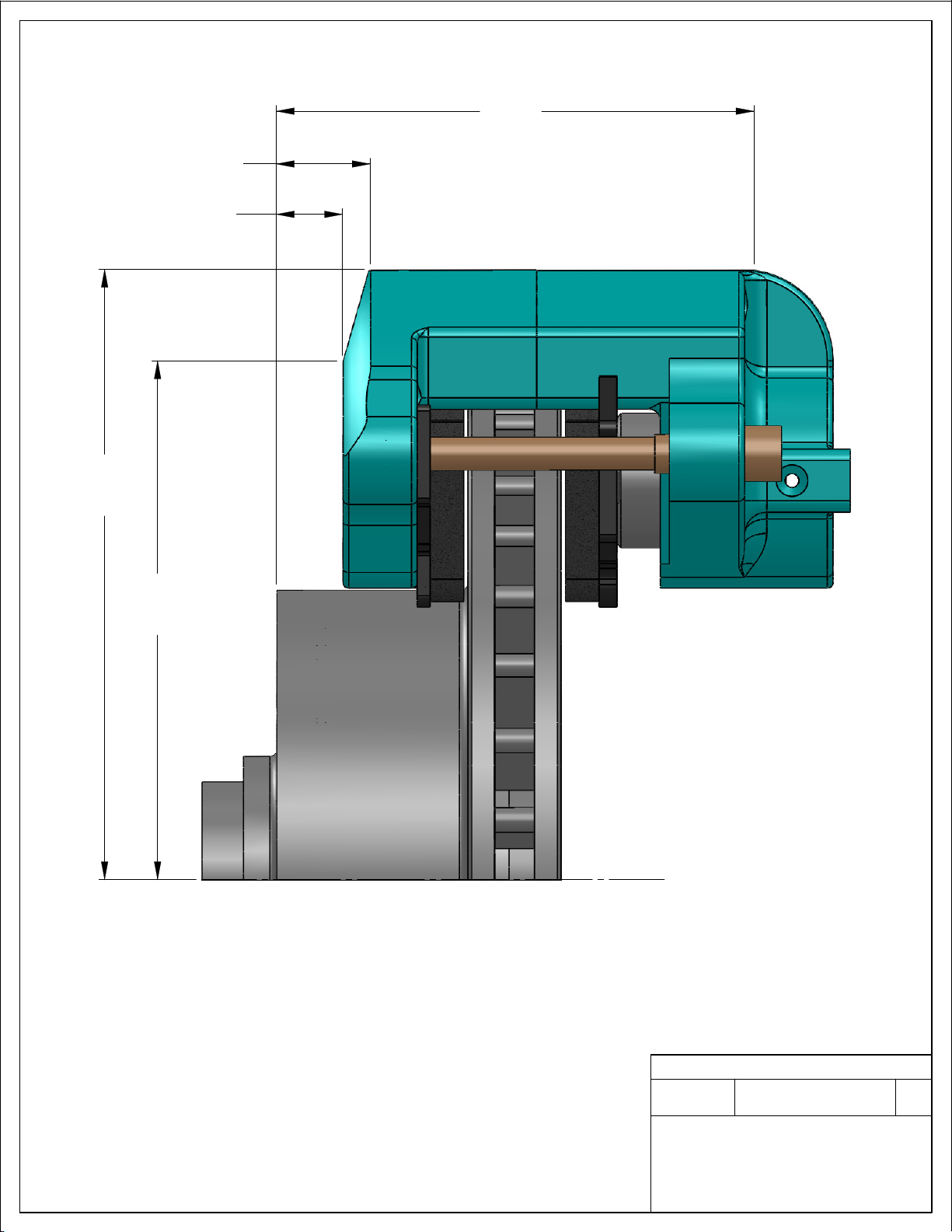
6.84
6.47
C
L
.74
1.05
5.33
-
WWW.SSBRAKES.COM
REV
T-032 DRAWING
Ph: 716-759-8666 / 800-448-7722 ~ Fx: 716-759-8688
TEMPLATE NO.
SSBC
STAINLESS STEEL BRAKE CORP.
CLARENCE, NEW YORK 14031-1720
DO NOT SCALE
DIMENSIONS ARE IN INCHES
This manual suits for next models
1
Other SSBC Automobile Accessories manuals


