Fastway flip 88-00-6525 Owner's manual
automatic
jack foot
TM
®
Installation
and Operation
Instructions
1
2
3
4
5
6
Drill Guide
Pilot Hole
Base Plate
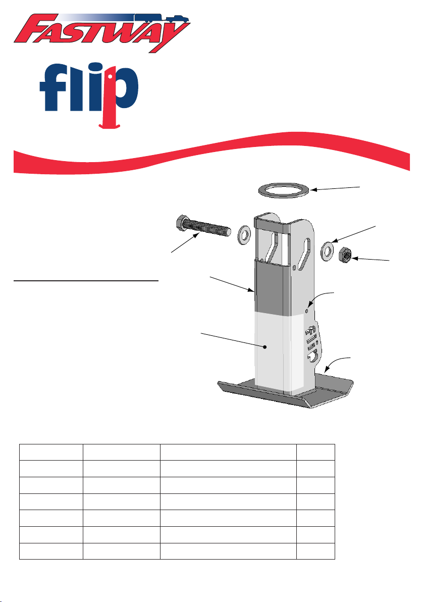
Fig. # Part # Description Qty.
1 88-01-6225 Spacer Ring (1 3/4” I.D.) 1
2 90-04-9110 1/2” Washer 2
3 90-04-9285 1/2” Nylock nut 1
4 BD088-2WS Warning Sticker 1
5 88-01-6625 Flip Automatic Jack Foot 1
6 88-01-6155 1/2” x 2-3/4” bolt 1
Tools Needed for Installation:
• 3/16” Metal Drill Bit
• 1/2” Metal Drill Bit
• Drill
• Wood Block
• (2) 3/4” wrenches
• Measuring tape
• Pencil or scratch awl
• Center punch
Model 88-00-6525
For 2” Jacks
Parts Breakdown
www.FastwayTrailer.com Fastway Flip...Faster, Easier.™

Page 2
• Read entire instruction manual before using this product. Failure to
do so can result in serious injury or death.
• Never exceed max 1,400 lb. tongue weight rating.
• Do not use to support trailer parked on grade greater than 3% (1.72°).
• Chock tires on both sides while supporting trailer with jack foot.
• Do not support trailer with jack foot placed on un-level ground or
debris. Jack foot base plate must be in complete contact with ground.
• Support tongue weight with jack foot in vertical position only when
attachment bolt is resting at bottom of guide slot.
• Replace worn or faded safety label immediately.
• Install only on a 2” jack with a 1-3/4” outside dimension inner jack
tube.
• Always use adequate personal protective equipment when installing.
• Wear safety glasses when installing.
• Avoid pinch points between jack extension, spacer ring, jack, and
trailer frame when retracting jack.
WARNING
CAUTION

Page 3
Install Flip™jack foot with trailer parked on level
ground both side-to-side and front-to-back.
Never exceed max 1,400 lb. tongue weight rating.
Install only on a 2” jack with a 1-3/4” outside dimension inner jack
tube.
STEP 2
Drill Hole in Jack
Step 2a - Options for Jacks with pre-existing holes in inner-jack tube
Step 2b - Locating hole in square jack
Step 2c - Locating hole in round jack
Step 2a - Options for Jacks with pre-existing holes in inner-jack tube.
Jacks with a pre-drilled holes may interfere with the Flip installation or
operation. Please read the following three options before going on to locating
the install hole for your Flip jack foot. You may need assistance from your
dealership when performing these options.
If your jack does NOT have a pre-existing hole at the bottom of the inner jack
tube, skip to Step 2b.
STEP 1
Locatetraileronaatlevelsurface, such as a driveway or parking lot. Chock
both sides of the trailer, and set tow vehicle parking brake. Keep trailer coupled
to tow vehicle, or place jack stands under trailer tongue to support trailer without
the use of the tongue jack. Disconnect trailer plug, safety chains, and safety
breakaway cable from the tow vehicle and move them out of the way.
Installation Instructions

Page 4
Option 2: Drill a 3/8” instead
of 1/2” hole, and use a 3/8” x
2 3/4” grade 5 bolt. This will
leave more material between the
holes. This is a good solution
for lower tongue weights. For
higher tongue weights, consider
option 1 or option 3.
Grade 5 bolts are
marked with 3 lines
on the head.
Option 2
3/8”
1-1/2”
Option 3: The third option, and best solution, is to
cut about 1/2” or more off the bottom of the inner
tube. Use a pipe cutter if possible, or a cutting wheel
or hack saw. Make the bottom as even as possible.
Somegrinding/lingmightbenecessarytomakea
good even bottom edge for the drill guide. By remov-
ing about 1/2” from the bottom, the drill guide will
then drill the hole with more material in between the
two holes. Although more work, this is the best solu-
tion.
If you have already drilled the hole as in options 1 or 2, but decide you don’t
like it, you can try option 3. Cut off at least 1/2” or more as needed.
Option 3
1/2”
1-1/2”
Cut
off
Always wear adequate personal protection equipment while
installing.
Wear safety glasses.
Option 1
1/2”
1-1/2”
Option 1: Drill the hole in the normal location.
There may be very little material between the two
holes, if any. This is okay, even if the holes interfere
slightly. The Flip will still function normally. It is
also okay if the thin bit of material between the holes
deforms, or even breaks apart. There will still be suf-
cientmaterialonthesidestoholdtheboltandliftthe
Flip.

Page 5
If you are installing the Flip jack foot on a square jack you cannot use the
guide holes pre-drilled in the Flip to locate the pilot holes as you can with a
round jack. The hole must be drilled free hand, or by removing the jack from the
trailer and using a drill press.
Looking at the driver’s side face of the jack,
measure up from the bottom of the inner jack
tube 1–1/2” and scratch or draw a mark. Then
measure 1/2 the distance between the front and
back faces of the tube and scratch or draw a line
thatcrossestherst.
This should be at 7/8” from both the front and
back on a 2” square jack with a 1-3/4” inner jack
tube.
Repeat this process for the passenger side face of
the inner jack tube.
Use a center punch to make a mark at these
locations on both sides of the jack.
Drill two 3/16” pilot holes on both sides using
these punch marks as a guide to start the hole.
Switch drill bits, and use a 1/2” bit to enlarge both pilot holes. Pass the drill
bitcompletelythroughthejacktomakesurethe1/2”installationboltwillt
smoothly.
Skip to STEP 3 to continue the Flip installation.
If you are installing the Flip jack foot on a round jack, skip to step 2c.
Step 2b - Locating hole in square jack
Mark with center punch on
both sides. Drill 3/16” pilot
hole, then 1/2” install hole.
7/8” 7/8”
1-1/2”
Page 6
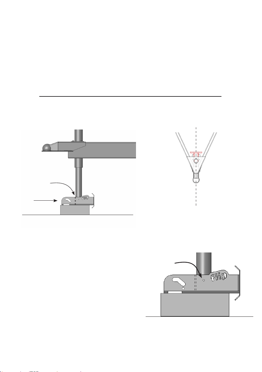
Use drill guide pilot hole to drill
3/16” pilot holes on each side of
inner jack tube.
3/16” drill guide
pilot holes
Push jack foot backward(1) so that
inner jack tube is tight to locating
plate(2).
1
2
Make sure jack foot is placed
parallel to the trailer before
drilling guide holes.
Use the 3/16” bit and drill a pilot hole
on each side of the jack tube using the
drill guide pilot holes on both sides of the
jack foot as guides. Retract the jack to a
comfortable drilling height, and remove
the Flip jack foot and the wood block.
Use the 1/2” drill bit to enlarge a pilot
hole. Once the tube wall has been
penetrated, ream out the hole slightly to
de-burr it and open it up. Switch sides,
Step 2c - Locating hole in round jack
RetractthetonguejackfarenoughthatyoucantthewoodblockandFastway®
Flip™jack foot under the inner-jack tube. Place the wood block on the ground,
and place the jack foot on top, face down with the base plate toward the back of
the trailer.
Slowly extend the jack tube until it rests on the jack foot and wood block, and so
that the locating plate is pushed up tightly against the front wall of the inner jack
tube.
The drill guide holes should be perpendicular to the trailer and jack tube. They
should be 1-1/2” from the bottom of the tube, and centered on the tube.
Extend the jack until the weight resting on the Flip jack foot holds it securely in
place so that it will not move while the guide holes are being drilled.

Page 7
STEP 4
Slide the spacer ring up the inner jack tube and hold it up while you position
the jack foot to bolt it on. Position the jack foot around the inner jack tube so that
the slot at the top lines up with the 1/2” holes just drilled in the jack tube. You
may need to retract the jack.
Slide a 1/2” washer onto the 1/2” bolt, and slide the bolt through the slots in the
jack foot and holes in the jack tube. Slide the 1/2” washer onto the other end of
the bolt, and thread on the Nylock nut. Tighten the nut securely, and then loosen
Enlarge with 1/2” drill bit.
7/8” 7/8”
C
1-1/2”
On a round jack the spacer ring must be in place or the jack foot will
not ‘flip’ up completely. A square jack does not need a spacer ring for
the Flip jack foot to operate correctly.
STEP 3
If drilling the holes leaves a burr or lip,
usealeorgrindertosmooththeedge
so that the pivoting operation of the Flip
jack foot is not disrupted.
and drill and ream the second hole. Pass the drill bit
all the way through the inner jack tube to make sure
there is a clean path for the bolt all the way through
the tube.

Page 8
NOTE: If your jack does not retract
far enough to make the Flip automatic
jack foot rotate up completely, or
if there is an obstruction below the
frame that keeps the jack foot from
rotating completely, you may add
additional rings to take up that
space.
Additional rings are available from
your dealership, or directly from
Fastway®at
www.FastwayTrailer.com More than one ring can be used
if necessary.
it only to the point that the Flip jack foot can
pivot freely up and down, but not enough that it is
sloppy or that there is too much play between the
jack foot and the inner jack tube. If the jack foot
does not drop smoothly into place, this nut may
need to be loosened slightly.
A small amount of lubricant helps the Flip
rotate more freely. Do not use petroleum based
grease. Use a wax-based bicycle chain lubricant
or a spray-on, silicone-based lubricant that
naturally repels dust and dirt. Apply lubricant to
any surface area that rubs against another during
Flip foot operation, such as the top and bottom
of the 1 3/4” ring, top of the Flip foot, and inner
edges of the bolt-guide slot. Wipe off any excess. Finished assembly of Flip
jack foot on round jack.
Lubricate
here
Page 9
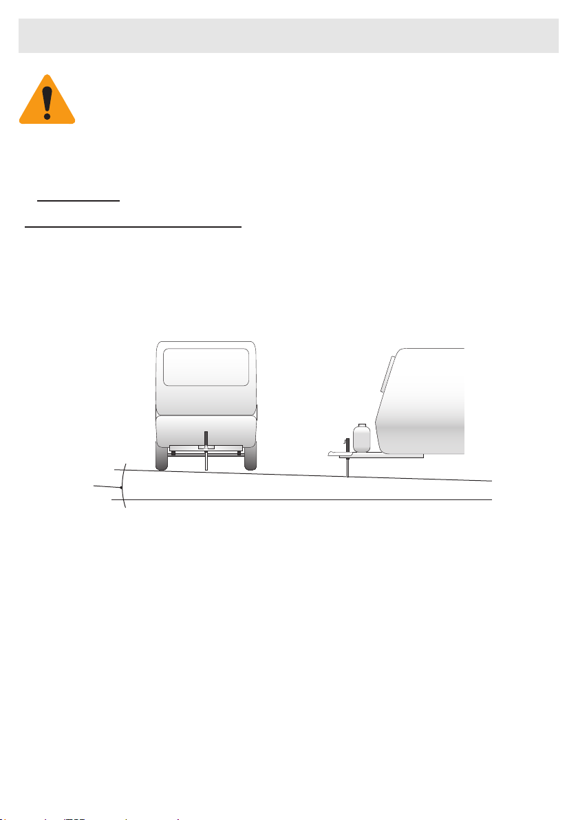
Do not use to support trailer parked on grade greater than 3%
(1.72°).
Do not support trailer with jack foot resting on un-level ground or
debris.
Jack foot base plate must be in complete contact with ground.
Instructions for Use
Do not use Flip with trailer parked on a slope
steeper than a 3% grade, or 1.72 degrees.
3%
1.72°
Also make sure that the spot where the jack foot will rest is as level as
possible, and free from debris like sticks or stones that might keep the jack foot
from being completely supported.
Chock the wheels on both sides of the trailer securely. Disconnect trailer plug,
safety chains, and breakaway cable from the tow vehicle. Uncouple the coupler,
and extend the jack to raise the coupler off the ball.
If using a weight distributing hitch, you may use the jack foot to raise both the
tow vehicle and trailer to make it easier to disconnect the hitch. Once the spring
arms are disengaged, lower the trailer and tow vehicle back to a point where the
tow vehicle is supporting all of the trailer’s tongue weight. Uncouple the coupler,
and extend the jack to raise the coupler off the ball.
STEP 5
When uncoupling your trailer:
Make sure that the trailer is parked on relatively level ground. Most
improved campsites, such as those found in private and public campgrounds are
fine. Pay special attention to the site when dry camping to make sure the slope is
not more than a 3% grade ( 1.72° ) either side-to-side or front-to-back.

Page 10
STEP 6
The Flip jack foot is designed to
straighten automatically as more
weight is applied. At times it may be
helpful to move it forward slightly with
your foot to make sure it sits directly
below the jack so that the jack tube rests
correctly at the bottom of the bolt slot,
and against the front of the jack foot or
on top of the support/locating plate.
If the full tongue weight is placed on the
jack with the jack foot out of position,
the inner jack tube can bend, resulting in
improper function of the jack or jack foot.
It may also damage the jack foot or trailer.
STEP 7
If you must drop the trailer in a place where
there is not enough clearance below the jack
for the Flip jack foot to pivot down properly,
the jack may be extended with the jack foot in
a horizontal position. A small block of wood
placed directly under the inner jack tube will
help keep the weight from bending the Flip jack
foot.
Correct Incorrect
Support tongue weight with jack foot in vertical position only
when attachment bolt is resting at bottom of guide slot.
Low ground clearance option.

Page 11
STEP 8
To couple your trailer:
Back the hitch ball under the
coupler. Retract the tongue jack
until the coupler rests on the hitch
ball. Lock the coupler. If you are
using a weight distributing hitch,
extend the jack and tension the
weight distribution bars.
Retract the jack completely until
the flip rotates up and out of the
way for towing. Do not force the jack handle after the jack has reached the top of
travel. Rotate it back slightly if necessary for towing.
Don’t force jack. Rotate back
slightly if necessary.
Limited One Year Warranty
Progress Mfg. Inc. warrants, to the original purchaser, this product against
defects in materials and workmanship for a period of one year from date of
purchase. This warranty does not cover damage due to normal wear and
tear, misuse, neglect, abuse, or product nish. Progress Mfg. Inc. reserves the
right to repair or replace the defective part(s) at their discretion. Replace-
ment of product or refund constitutes the fulllment of all liabilities of Prog-
ress Mfg. Inc. under this warranty. For questions about warranty coverage
and warranty authorization, please call (877) 523-9103. If warranty repair
or replacement is approved, send the entire product and proof of purchase,
shipping pre-paid, to: Progress Mfg. Inc., 533 South 500 West, Provo, UT
84601
A Product of Progress Mfg. Inc.
Fastway®Trailer Products
533 South 500 West, Provo, UT 84601
(877) 523-9103
www.FastwayTrailer.com
FLIN_0610
© 2009 Copyright Progress Mfg. Inc., All rights reserved.
TM
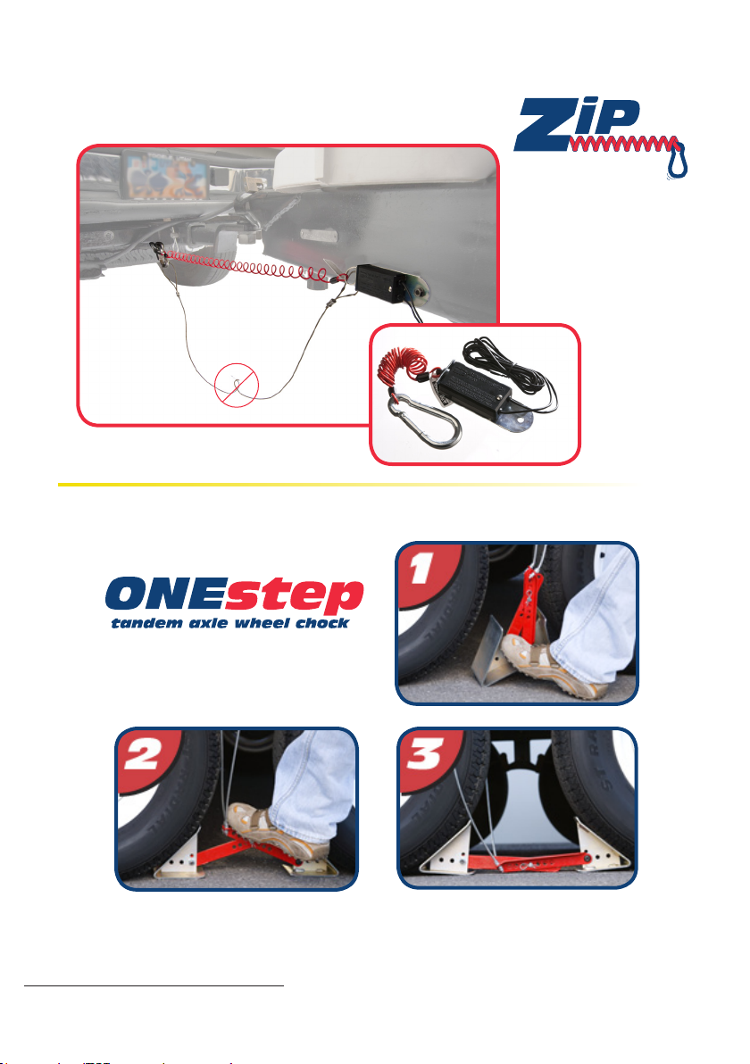
Other Great Fastway Products!
The Fastway®Zip™ breakaway cable’s coiled
design keeps your cable from dragging! TM
Trailer Breakaway
Cable & Switch
Easy as...
Fastest and easiest tandem axle wheel chock ever!
All products patent pending.
Table of contents
Other Fastway Automobile Accessories manuals


Popular Automobile Accessories manuals by other brands


ULTIMATE SPEED
ULTIMATE SPEED 279746 Assembly and Safety Advice

SSV Works
SSV Works DF-F65 manual

ULTIMATE SPEED
ULTIMATE SPEED CARBON Assembly and Safety Advice

Witter
Witter F174 Fitting instructions

WeatherTech
WeatherTech No-Drill installation instructions

TAUBENREUTHER
TAUBENREUTHER 1-336050 Installation instruction