SSD Drives 631 series User manual

07-01-08-02-E-V0500
Series

Getting Started 1-1
631 Digital Servo Drive 07-01-08-02-E-V0500
1GETTING STARTED
Introduction
The 631 Digital Servo Drive is designed to control Eurotherm approved AC Brushless Servo
Motors. It is available in a range of current ratings from 1 to 6 Amps.
Set-up
The EASYRIDER software <is used to set-up the drive. An “Autopilot” set-up wizard can be
started when using the software.
Programming
The “BIAS” progamming language is contained in EASYRIDER <which provides for up to
1500 lines of program code.
Operation
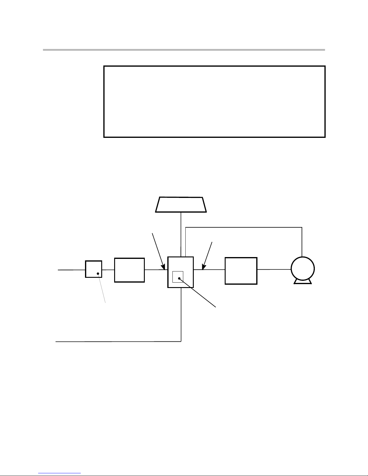
The unit is operated remotely using the analog/digital inputs and outputs via a PLC, for example.
Multiple units can be controlled using RS232, CAN-Bus or Incremental Bus.
Four operating modes offer various speed, torque and position controls.
There is a seven-segment diagnostic display for trip and fault finding information.
The internal RFI filter offers enhanced EMC compliance without the need for additional external
components.
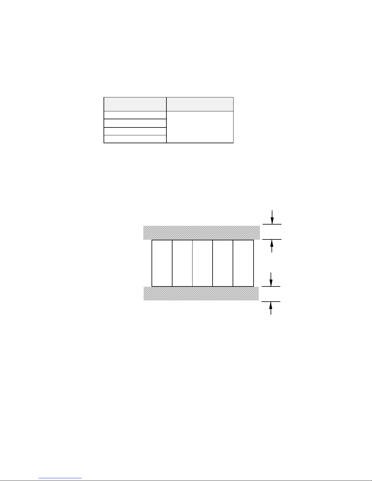
An internal dynamic brake resistor is provided.
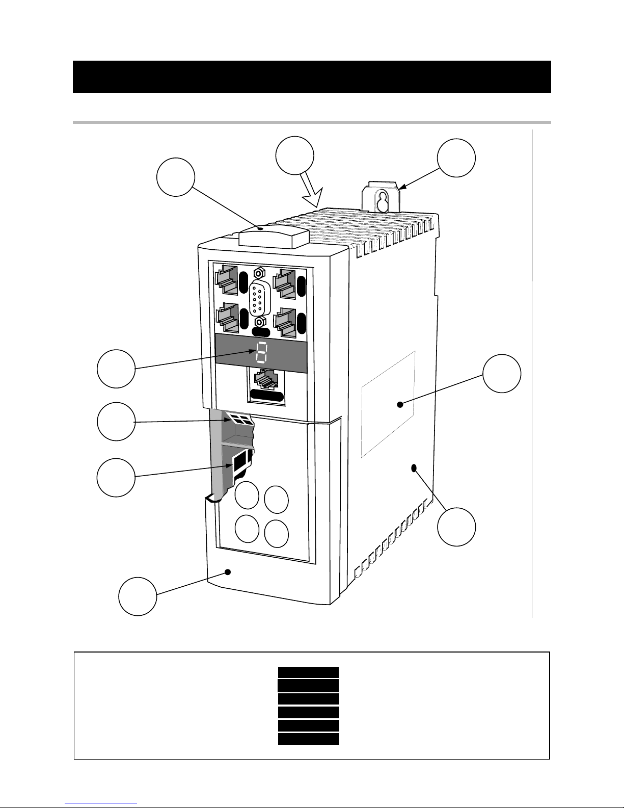
Equipment Inspection
•Check for signs of transit damage
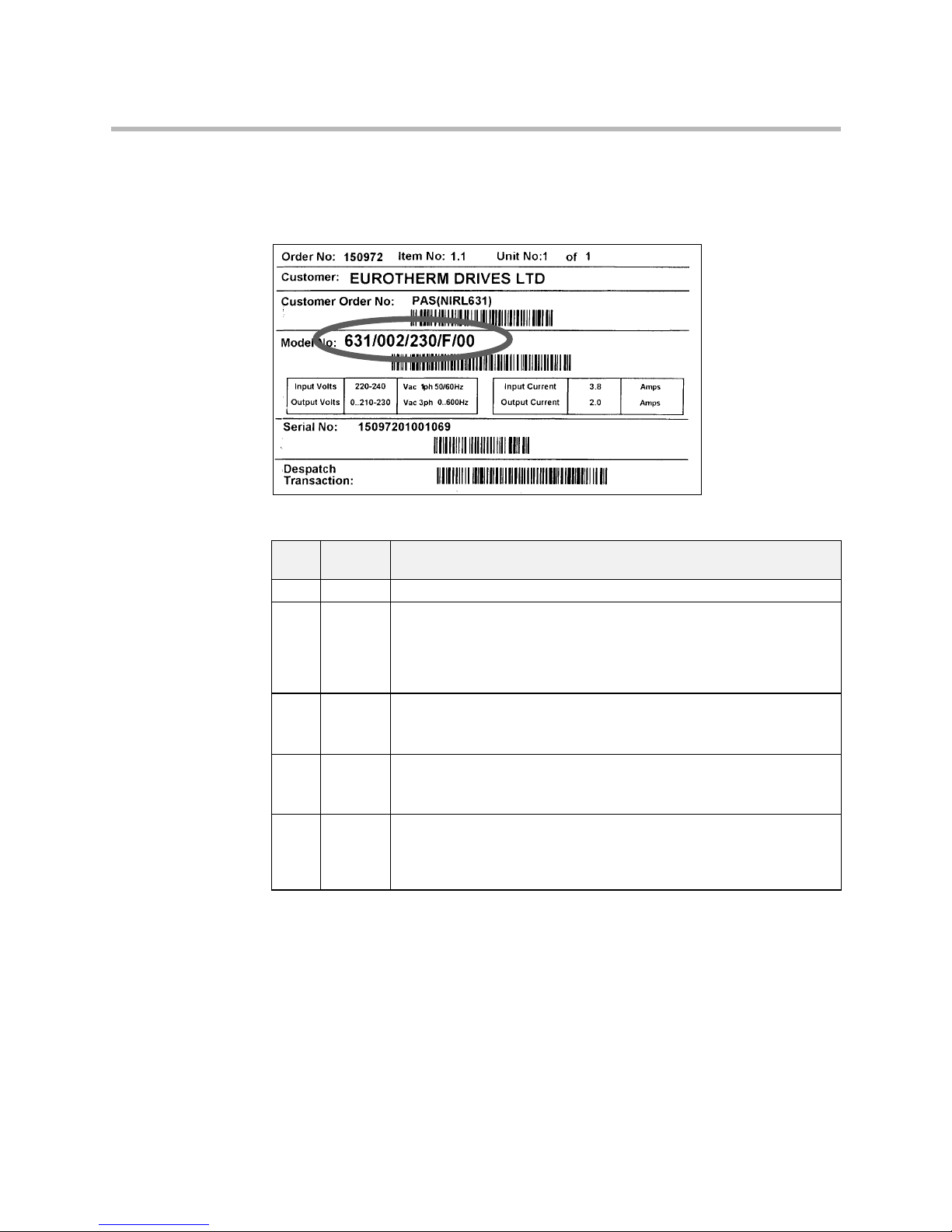
•Check the product code on the rating label conforms to your requirement.
If the unit is not being installed immediately, store the unit in a well-ventilated place away from
high temperatures, humidity, dust, or metal particles.
Refer to Chapter 2: “An Overview of the Servo Drive” to check the rating label/product code.
Refer to Chapter 8: “Routine Maintenance and Repair” for information on returning damaged
goods.
Refer to Chapter 9: “Accessories” to check for the correct items.
About this Manual
This manual is intended for use by the installer, user and programmer of the 631 Servo Drive. It
assumes a reasonable level of understanding in these three disciplines.
Note:
Please read all Safety Information before proceeding with the installation and operation
of this unit.
Enter the “Model No” from the rating label into the table at the front of this manual. It is
important that you pass this manual on to any new user of this unit.
Initial Steps
Use the manual to help you plan the following:
Installation
Know your requirements:
•certification requirements, CE/UL/CUL conformance
•conformance with local installation requirements
•supply and cabling requirements

1-2 Getting Started
07-01-08-02-E-V0500 631 Digital Servo Drive
Operation
Know your operator:
•how is it to be operated, RS232, CAN-Bus?
•what level of user is going to operate the unit?
Programming (Operator Station or suitable PC programming tool only)
Know your application:
•select the appropriate Operating Mode
•plan your “programming”
•enter a password to guard against illicit or accidental damage
How the Manual is Organised
The manual is divided into chapters and paragraphs. Page numbering restarts with every chapter,
i.e. 5-3 is Chapter 5, page 3.
Further descriptions,
that relate to this document.
Associated Documentation
UL:4.2.2
Absolute encoder with CAN
UL:7.5.3.3
Bus Interface CAN for 631
UL:9.5.1
Intelligent Operator-Terminal
IBT - Product Description
UL: 10.6.4
EASYRIDER software
UL: 10.6.5
BIAS - Command Description
UL: 10.6.6
Serial transfer protocol
EASY-serial 631 - Product Manual
UL: 12
Accessories
HA388879 EMC Installation Guidelines for Modules and Systems

An Overview of the Servo Drive 2-1
631 Digital Servo Drive 07-01-08-02-E-V0500
2AN OVERVIEW OF THE SERVO DRIVE
Component Identification
X
2
1
X
4
1
X
2
0
X
4
0
X30
X
1
5/RS
232
7
1
2
3
5
4
6
8
9
Figure 2-1 View of Component Parts
1Main servo drive assembly 9Power terminal (X1)
2Product code label X15/RS232 Set-up service connection (EASYRIDER <)
3Terminal cover X20 CAN-Bus input connection
4Diagnostic display X21 CAN-Bus output connection
5Electronic ground connection X30 Resolver connection
6External brake resistor connection X40 Pulse interface, multi-function, input connection
7Adjustable mounting clip X41 Pulse interface, multi-function, output connection
8Control terminal (X10)

2-2 An Overview of the Servo Drive
07-01-08-02-E-V0500 631 Digital Servo Drive
Control Features
POWER
X
2
1
X
4
1
X
2
0
X
4
0
X30
X
1
5/RS232
X
2
1
X
4
1
X
2
0
X
4
0
X30
X
1
5/RS232
Resolver Connection
(mandatory)
Motor 1
Motor 2 (synchronised to Motor 1)
POWER
Encoder/Stepper connection
to next 631 controller
CAN-Bus connection
to next 631 controller
(last controller is terminated)
CAN-Bus terminator
EASYRIDER software
used to configure
each 631 individually
The Servo Drive is controlled via RS232, CAN-Bus or Incremental Bus using a PLC. It is
configured using the EASYRIDER software.
General
GeneralGeneral
General Operating Modes Pulse/direction Input
±10V velocity control
Torue control
Position control
Encoder follower
Motion control
BIAS - motion language
CAM profiling
Setup, Service,
Programming
EASYRIDER software
Communications
Interfaces
CAN-Bus
RS232
Incremental Bus
Diagnostics Diagnostic facility
Protection
ProtectionProtection
Protection Trip Conditions Heatsink overtemperature and
Functions Multiple protection functions - refer to Chapter 7
Inputs/
Inputs/Inputs/
Inputs/
Outputs
OutputsOutputs
Outputs
Inputs ±10V (12 bit) setpoint
4 In: 24V DC
Outputs 2 Out: 24V DC
Table 2-1 Control Features

An Overview of the Servo Drive 2-3
631 Digital Servo Drive 07-01-08-02-E-V0500
F
Instructions
x
Programming
$
Diagnostics
?
Setup
EASYRIDER <
7x
$?
PLC
Custom-made Software
:Fx
$?
o
PLC I/O ±10V F$
oX10
631 Servo Drive
current-loop
speed-loop
position-loop
°
PLC
RS232
X15
CAN-Bus
X20/X21
F
Figure 2-2 Communications Options
(analog setpoint value)
Pos.1 Pos.2
M
Synchronisation
(electronic gearbox)
1 : X
CAN-Bus Network
631
Unit X
631
Unit Y
CAN
Pulse Control
631
AC Servo
Stepper motor
CAM Profiling
Pos X
Pos Y
631
+10V -10V
R
M
Point-to-Point
Position Control
control or
Conventional Control
incremental
encoder
Figure 2-3 Typical Applications

2-4 An Overview of the Servo Drive
07-01-08-02-E-V0500 631 Digital Servo Drive
Understanding the Product Code
The unit is fully identified using a five block alphanumeric code which records how the Servo
Drive was calibrated, and its various settings when despatched from the factory.
The Product Code appears as the “Model No.”. Each block of the Product Code is identified as
below:
Block
No.
Variable Description
1 631 Generic product
2 XXX Three numbers specifying the rated output current
001 = 1A
002 = 2A
004 = 4A
006 = 6A
3 XXX Three numbers specifying the nominal input voltage rating:
230 220 to 240V (±10%) 50/60Hz
4 X One character specifying the use of the Internal EMC RFI Filter:
F = Filter
0 = No Filter
5 XX Two digits specifying mechanical package including livery and mechanical
package style, and any option installed over and above the standard
features of the product:
00 Eurotherm Standard
Example
631/002/230/F/00
Servo Drive Type 631, rated output current 2A, AC supply 230V, with internal filter.

Installing the Servo Drive 3-1
631 Digital Servo Drive 07-01-08-02-E-V0500
3INSTALLING THE SERVO DRIVE
IMPORTANT: Read Chapter 12: “Certification for the Servo Drive” before installing this unit.
EMC Installation Hints
All components are mounted on a mounting plate (minimum thickness
3mm) inside a steel cubicle. 3mm
Ensure good grounding of the complete system, including the ground
connections between the cubicle and machine.
If more than one mounting plate, interconnect with copper rails.
Place all wires and cables as close as possible to any grounded metal
planes. Position control cables close to grounded metal parts when
exiting the control cubicle.
Separate “dirty”, “clean” and “sensitive” cables if possible by at least
30mm. Cables should cross at 90°.
Avoid cable loops, especially between the line filter and drive which
should be as close and as short as possible (drilled).
0,3 m 90°
Only remove the required length of screen from the end of the cable.
8 cm max
Make screen connections as advised in this manual. Keep screened
cables as short as possible, ground screens at both ends. For long
cables, make additional screened connections along the cable length.
Connect screens to good quality grounding points. Use U-clips to give
a 360°connection.
Connect any unused wires in the cables to ground.
Use only Eurotherm cables for motor and resolver. Refer to Chapter 9: “Accessories”

3-2 Installing the Servo Drive
07-01-08-02-E-V0500 631 Digital Servo Drive
Mechanical Installation
W
H2 H1
H
W1
D
H3
easily re-positioned to allow
different mounting configurations
Fixing hole
centres
DIN mounting
dimensions
SIDE VIEW PANEL MOUNTING VIEW DIN MOUNTING VIEW
A
djustable mounting clip can be
Figure 3-1 Mechanical Dimensions for 631
631 Model Number
631 Model Number631 Model Number
631 Model Number H
HH
HH1
H1H1
H1 H2
H2H2
H2 H3
H3H3
H3 W
WW
WW1
W1W1
W1 D
DD
DFixings
FixingsFixings
Fixings
631 /001 /230/ .... Mounting holes 5.5mm
631 /002/ 230/ .... 183.0 188.0 205.0 151.0 72.0 36.0 175.0 Use M5 fixings
631 /004/ 230/ .... (7.2) (7.4) (8.1) (5.9) (2.8) (1.4) (6.9) Weight 1.5kg (3.3lb) approximately
631 /006/ 230/ ....
All dimensions are in millimetres (inches)
Note:
Additional space is required to the front of the unit for the signal mating plugs,
approximately 45mm.
Mounting the Servo Drive
The unit must be installed in a vertical position to guarantee the best air circulation for the
cooling ribs of the heat sink. Vertical installation above other drive racks or above other heat
producing devices can lead to overheating.
You must install the unit inside a suitable cubicle. The inside of this cubicle must be free from
dust, corrosive fumes, gases, and all liquids including condensation.
If the unit is being installed in a place where condensation is likely, install a suitable
anticondensation heater. The heater must be SWITCHED OFF during normal operation.
Automatic switch off is recommended.

Installing the Servo Drive 3-3
631 Digital Servo Drive 07-01-08-02-E-V0500
Minimum Air Clearances
Cubicle Size
The digital servo drive is protected against damage caused by overheating.
There is a thermal sensor installed on the heat sink. When the temperature rises to >95°C, the
drive is automatically switched off. This setting cannot be changed. Use a cabinet of the correct
size for adequate air circulation, see below.
631 Model Number
631 Model Number631 Model Number
631 Model Number Volume of Cubicle
Volume of CubicleVolume of Cubicle
Volume of Cubicle
(minimum)
(minimum)(minimum)
(minimum)
631 /001 /230/ ....
631 /002/ 230/ .... 0.12m³
631 /004/ 230/ ....
631 /006/ 230/ ....
Ventilation
The servo drive gives off heat in normal operation and must therefore be mounted to allow the
free flow of air through the ventilation slots and heatsink. Maintain minimum clearances for
ventilation as shown below to ensure heat generated by other adjacent equipment is not
transmitted to the Servo Drive. Be aware that other equipment may have its own clearance
requirements. When mounting two or more 631s together, these clearances are additive.
Ensure that the mounting surface is normally cool.
100mm / 4"
100mm / 4"
631 631 631 631 631
General Rule:
It is better to place heat-producing devices low down inside an enclosure to support internal
convection, which will spread the heat. If placing devices up high is unavoidable, you should
consider increasing the (upper) dimensions of the cubicle, or installing fans.

3-4 Installing the Servo Drive
07-01-08-02-E-V0500 631 Digital Servo Drive
Electrical Installation
IMPORTANT: Please read the Safety Information on page Cont. 3 & 4 before proceeding.
WARNING!
Ensure that all wiring is electrically isolated and cannot be made “live”
unintentionally by other personnel.
All control/resolver/motor thermistor inputs,
i.e protected by double insulation are SELV.
Do not connect to non-SELV circuits.
(Refer to Chapter 11: “Technical Specifications” - Insulation Concept).
Note:
Refer to Chapter 11: “Technical Specifications” for additional Cabling Requirements and
Terminal Block Wire Sizes.
IMPORTANT: The use of variable speed drives of all kinds can invalidate the certification for dangerous
areas (apparatus group and/or temperature class) of explosion-protected motors.
Inspection and certification for the complete installation of servo motors and electronic
components must
mustmust
must be obtained.
631 motor
(noisy)
brake resistor
(noisy)
signal/control cable
(sensitive)
power
supply
(clean)
cable
fuse or suitable
circuit breaker
(RCD not recommended)
line
choke (noisy)
motor
cable
(an external ac supply EMC filter
internal ac supply EMC filter
must not be used with the
internal filter)
(optional)
resolver cable (sensitive)
(if required)
motor
choke
(if requiredl)
(noisy)
Figure 3-2 Cabling Requirements
Cables are considered to be electrically sensitive, clean or noisy. You should already have
planned your cable routes with respect to segregating these cables for EMC compliance.
If not, refer to Chapter 12: “Certification for the Servo Drive”.

Installing the Servo Drive 3-5
631 Digital Servo Drive 07-01-08-02-E-V0500
Remove Terminal Cover by pressing here and pulling down
631
Using Cage Clamp Terminals
Remove the terminal cover as shown above.
Insert a flat-bladed screwdriver (size 3.5 mm max.) inside the smallest
hole. Lever the screwdriver, keeping it firmly pressed into the hole. The
cage will open.
Insert the stripped wire (5mm to 6mm/0.22in.) or wire crimp inside the
cage keeping the screwdriver in position.
Remove the screwdriver. Note the cage provides the correct force for a
secure connection.
Motor Thermistor
Refer to Chapter 12: “Certification for the Servo Drive” - Solid State Motor Overload
Protection.
WARNING!
The servo drive thermistor connections are for SELV only.
Eurotherm servo motors series ACM 2n, ACR n and ACG are SELV,
other manufacturer’s motors may not be.
If you use a non-Eurotherm servo motor, make sure that the thermistor is insulated
to SELV from live parts inside the motor. If not, the thermistor signals have to be wired
separately and an additional isolation circuit must be provided before connecting to
X30.
Make sure that pins 2 and 6 of X30 are only served by SELV insulated cable leads.
631 motor
resolver cable (without thermistor connections)
SELV Isolation
thermistor wires
X30
Earth Fault Monitoring Systems
We do not recommend the use of circuit breakers (e.g. RCD, ELCB, GFCI), but where their use
is mandatory, they should:
•Operate correctly with dc and ac protective earth currents (i.e. type B RCDs as in
Amendment 2 of IEC755).
•Have adjustable trip amplitude and time characteristics to prevent nuisance tripping on
switch-on.

3-6 Installing the Servo Drive
07-01-08-02-E-V0500 631 Digital Servo Drive
When the ac supply is switched on, a pulse of current flows to earth to charge the
internal/external ac supply EMC filter’s internal capacitors which are connected between phase
and earth. This has been minimised in Eurotherm Drives’ filters, but may still trip out any circuit
breaker in the earth system. In addition, high frequency and dc components of earth leakage
currents will flow under normal operating conditions. Under certain fault conditions larger dc
protective earth currents may flow. The protective function of some circuit breakers cannot be
guaranteed under such operating conditions.
WARNING!
Circuit breakers used with VSDs and other similar equipment are not
suitable for
personnel protection. Use another means to provide personal safety. Refer to
EN50178 (1998) / VDE0160 (1994) / EN60204-1 (1994)
Wiring the Servo Drive
Earth Connections
WARNING!
Due to the working principle of servo drives or filters, there will be an eart leakage
current exceeding 10mA dc, 3.5mA ac.
IMPORTANT: Refer to “Earth Fault Monitoring Systems”. page 3-5.
The wiring terminals accept a maximum conductor size of 12 AWG (3.2mm²).
The servo drive, when fitted with an internal ac supply EMC filter, is only suitable for earth
referenced supplies (TN).
Refer to Chapter 12: “Certification for the Servo Drive” for information on earthing
requirements.
DBR1 & DBR2 - External Brake Resistor
Refer to Chapter 13: “Application Notes” - Dynamic Braking for selection details and Chapter
11: “Technical Specifications” - Power Details.
DBR1
DBR2
Top View of 631
Figure 3-3 External Brake Resistor Terminals
Caution
The resistor should be mounted on a heatsink (back panel) and covered to prevent injury
from burning.

Installing the Servo Drive 3-7
631 Digital Servo Drive 07-01-08-02-E-V0500
X1 - Motor and Power Wiring Connections
M3/W
M2/V
M1/U
L2/N
L1
123456 78910
Power
Servo Motor
To Motor Brake
Screen Connections - ensure good
connection with conductive surface
on the cubicle, remove varnish.
control circuitry
red
blue
Motor Cable Clamp
X1
230V ac 50/60Hz supply
motor supply
motor supply
motor supply
protective earth
protective earth
Figure 3-4 631 Power and Earth Wiring Connections
Note:
The unit must be permanently earthed using two independent earth conductors using X1.
Protect the incoming mains supply using a suitable fuse or circuit breaker as shown in
Chapter 11: “Technical Specifications” - Power Details.
Motor Cable Clamp
In order to conform with the specified generic EMC standards, the motor cable must be screened
and the screen connected to both the motor frame and the motor cable clamp. This clamp is
internally connected to power terminals PE (Protective Earth) and provides convenient 360°
connection. It is used for the motor protective earth, motor and control cable screen connections.
Refer to Chapter 12: “Certification for the Servo Drive” for information on meeting generic
EMC standards and minimising electrical interference.

3-8 Installing the Servo Drive
07-01-08-02-E-V0500 631 Digital Servo Drive
X10 - Control Wiring Connections
M3/W
M2/V
M1/U
L2/N
L1
123456 78910
Control
X10
Screen Connections:
ensure good connection
on the cubicle.
Control Cable
Retainer
cubicle backplate providing clean earth
for electronic ground and screens
with conductive surface
Remove varnish.
Functional Earth connected to
Figure 3-5 631 Control Wiring Connections
Pin Type Function
1±10V, Ri - 10kΩANALOG IN, differential to pin 2
referenced to GND
2±10V, Ri - 10kΩANALOG IN, differential to pin 1
referenced to GND
3 0V PLC External supply for digital i/o,
related to pin 4
4 24V DC PLC External supply for digital i/o,
related to pin 3
5 Opto-OUT Configurable <(s. 3.1.1)
6 Opto-OUT Configurable <(s. 3.1.1)
7 Opto-IN ACTIVE, non-configurable
activates motor power when high
8 Opto-IN Configurable <(s. 3.1.1)
9 Opto-IN Configurable <(s. 3.1.1)
10 Opto-IN Configurable <(s. 3.1.1)

Installing the Servo Drive 3-9
631 Digital Servo Drive 07-01-08-02-E-V0500
Note:
Use screened control cables to comply with EMC requirements.
All control and signal terminals are SELV, i.e., protected by double/re-inforced insulation.
Ensure all wiring is rated for the highest system voltage. Control wiring of between 0.08 mm2
(28 AWG) - 2.5 mm2(14 AWG) can be used.
Control Cable Retainer
This clip is used to provide guaranteed segregation of the control and power cables. It may be
rotated in either direction to allow easy installation of the control cables.
Refer to Chapter 11: “Technical Specifications” for Control Terminal information.
Refer to Chapter 12: “Certification for the Servo Drive” for information on meeting generic
EMC standards and minimising electrical interference.
I/O supply
~
=
L1
N
DC +24V PLC
PLC
0V PLC
Functions according to user-software
X10
SELV Isolation
2345679
810
1
I/O Functions
to be installed by User
<
It may be useful to connect one pole directly to earth, refer to PLC information.
Analog
Digital
*
Analog Output. Polarity according to requirement. Setpoint output and input are working related to earth.
*
631 0V
according to
set-up with
EASYRIDER
Figure 3-6 Typical Connection to the Control Terminals (X10)

3-10 Installing the Servo Drive
07-01-08-02-E-V0500 631 Digital Servo Drive
X30 - Resolver Connection
IMPORTANT: Refer to the WARNING on page 3-5.
The resolver provides a digital value for the rotor position to within one revolution, evaluation:
12 or 14 bit. It is adjustable in the Configuration Menu in the EASYRIDER software.
•commutation according to pole pair number
•actual speed value
•incremental position output
•position value for position regulation
The supplied resolver cable is plugged in to the front of the 631 (socket X30), and into the
socket on the Eurotherm approved servo motor. This connection must be made for the 631 to
control the operation of the motor. The cable contains wiring for the resolver and the motor
thermistor.
891
712 10 2
611 3
54
1
2
3
4
5
6
7
8
9
solder side
motor end controller end (X30)
89
1
7
12
10
2
6
11
3
5
4
front
Pin No.
1
2
3
4
8
7
5
6
9
10
11
12
Pin No.
4
8
3
7
5
9
2
6
1
grey
white
brown
green
yellow
pink
red
blue
sin +
sin -
cos +
cos -
carrier +
carrier -
PTC optional
PTC optional *
screen
FunctionColour
1
2
3
4
5
6
7
8
9
front
solder side
screens can be connected to ground
with U-clip or gland using 360°connection
Figure 3-7 Resolver Connections (as supplied cable model KIR)
Note:
The plug type shown above is for use with Eurotherm motor types AC Mn only.
Refer to the Warning on page 3-5.

Installing the Servo Drive 3-11
631 Digital Servo Drive 07-01-08-02-E-V0500
X40/41 - Multi-function Input/Output Connections
This connection provides encoder emulation, encoder input and stepper motor interface.
Note:
Refer to Chapter 11: “Technical Specifications” - X40/X41 - Multi-function Input/Output.
X40 X41 X40 X41
631 631
Incremental-IN
SLAVE 1
Incremental-IN
SLAVE 2
mount units side-by-side if possible
GND GND GND
X40 X41
631
Incremental-Out
MASTER
keep cables as short as possible
X40/41 signals are referred to PE
Figure 3-8 Application Example
To synchronise several 631 servo drives, connect the X40/41 sockets as shown using the
specified cables. The 631 is configured using EASYRIDER software <.
The X40/X41 input/output functions are configurable using the EASYRIDER <software.
Functions:
Mode 0 Incremental Output
Mode 1 Incremental Input
Mode 2 Step Control Pulse/Direction
Mode 3 Step Control Pulse (+) ( -)

3-12 Installing the Servo Drive
07-01-08-02-E-V0500 631 Digital Servo Drive
X40/41 Mode 0 - Incremental Output
•Incremental encoder simulation for processing in positioning modules
•Standard: 1024 increments; other selectable pulse numbers are 512, 256, 128
A
/B
B
Z
/A
/Z
Incremental Encoder inputs or outputs
X40 X41
631
Incremental OUT
PLC
IN
Encoder Emulation,
based on Resolver
conversion
GND
X40
X40X40
X40 Pin
PinPin
Pin Function
FunctionFunction
Function X41
X41X41
X41
8-pole Modular Jack,
screened
EASYRIDER <X40 mode = 0 8-pole Modular Jack,
screened
1
8
GND
/Z
Z
/B
B
/A
A
5VI
X40 and X41 are identical and internally switched
in parallel.
(X40 = X41) therefore wiring is very easy.
1
8
GND
/Z
Z
/B
B
/A
A
5VI
internal connection to
GND
Case: Screened
1
11
1GND
2
22
2 inverted 0-Index OUT /Z
3
33
30-Index OUTZ
4
44
4 Channel B inverted OUT /B
5
55
5 Channel B OUT B
6
66
6 Channel A inverted OUT /A
7
77
7 Channel A OUT A
8
88
8Output supply voltage
5.5V dc max. 150mA
5VI
Design Rule
The capability of input frequency of any connected device must at least meet the selected value
of pulse outputs (increments) on X40.
n = maximum speed (rpm)
x = increments e.g. 1024
f = output frequency at X40/41 4,5,6,7
Formula: f=
n * x
50 =[Hz]
Example: n = 4000 rpm f=4000 * 1024
50 = 81920 Hz

Installing the Servo Drive 3-13
631 Digital Servo Drive 07-01-08-02-E-V0500
X40/41 Mode 1- Incremental Input
Parameter area of the input signals is 10 - 1,000,000 increments
A
/B
B
Z
/A
/Z
Incremental Encoder inputs or outputs
Encoder IN
Encoder
X40 X41
631
Mode = 1
Incremental IN
GND
X40
X40X40
X40 Pin
PinPin
Pin Function
FunctionFunction
Function X41
X41X41
X41
8-pole Modular Jack,
screened
EASYRIDER <X40 mode = 1 8-pole Modular Jack,
screened
1
8
GND
/Z
Z
/B
B
/A
A
5VI
X40 and X41 are identical and internally switched
in parallel.
(X40 = X41) therefore wiring is very easy.
1
8
GND
/Z
Z
/B
B
/A
A
5VI
internal connection to
GND
Case: Screened
1
11
1GND
2
22
2 inverted 0-Index OUT /Z
3
33
30-Index OUTZ
4
44
4 Channel B inverted OUT /B
5
55
5 Channel B OUT B
6
66
6 Channel A inverted OUT /A
7
77
7 Channel A OUT A
8
88
8Output supply voltage
5.5V dc max. 150mA
5VI
Note:
The operation of incremental encoders when using long cables may cause a voltage drop
of the encoder power supply. We suggest using an external supply if necessary.
Table of contents
Other SSD Drives DC Drive manuals
Popular DC Drive manuals by other brands

Vincent Associates
Vincent Associates UNIBLITZ DM412 instruction manual

Santerno
Santerno AMS90/1 Applications manual

Lenze
Lenze DISCO GST Series operating instructions

Pacific Scientific
Pacific Scientific MA6410 Installation & hardware reference manual

Maco
Maco HAUTAU EM 2 Mounting instructions

FujiFilm
FujiFilm FRENIC HVAC Series quick start guide

ABB
ABB ACH580 Series Installation, operation and maintenance manual

YASKAWA
YASKAWA PROFINET V1000 installation manual

Danfoss
Danfoss VLT AutomationDrive FC 302 Programming guide

ABB
ABB ACS 400V instructions

Danfoss
Danfoss AME 23 instructions

Rockwell Automation
Rockwell Automation Allen-Bradley PowerFlex 525 Product information