manuals.online logo
Brands
  1. Home
  2. •
  3. Brands
  4. •
  5. Festo
  6. •
  7. DC Drive
  8. •
  9. Festo DAPS-...-R-...-F...-...-MW Series User manual

Festo DAPS-...-R-...-F...-...-MW Series User manual

Translation of the original instructions
1 About this document
This document describes the use of the above-mentioned product.
1.1 Further applicable documents
– Certification documents
– Operating conditions EX
All available documents for the product èwww.festo.com/pk.
2 Safety
2.1 Safety instructions
General safety instructions
– Only use the product in original status without unauthorised modifications.
– Only use the product if it is in perfect technical condition.
– Observe labelling on the product.
– Take into consideration the ambient conditions at the location of use.
– Store the product in a cool, dry, UV-protected and corrosion-protected envir-
onment. Ensure that storage times are kept to a minimum.
– Prior to mounting, installation and maintenance work: Switch off compressed
air supply and secure it from being switched back on.
– Exhaust drive prior to assembly, installation and dismounting.
– Do not dismantle the cylinder end cap, fixed conduit and handwheel.
– The transmission shaft must not be actuated manually using an open-ended
spanner.
– Do not actuate the handwheel using a lever tool.
Operating medium
– Only use compressed air in accordance with the specifications
è 14 technical data.
– Use only unlubricated compressed air under normal conditions. Once the
product has been used with lubricated compressed air, it must continue to be
operated with lubricated compressed air only.
– Protect the device from pressure fluctuations.
Return to Festo
Hazardous substances can endanger the health and safety of personnel and
cause damage to the environment. To prevent hazards, the product should only
be returned upon explicit request by Festo.
– Consult your regional Festo contact.
– Complete the declaration of contamination and attach it to the outside of the
packaging.
– Comply with all legal requirements for the handling of hazardous substances
and the transport of dangerous goods.
2.2 Intended use
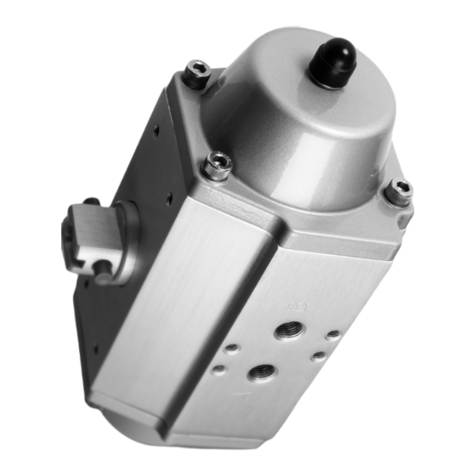
The semi-rotary drive DAPS-R is intended to actuate process valves that close to
the right, such as ball valves and butterfly valves, with a rotation angle from 0°
(valve closed)…90° (valve open).
NOTICE!
The operating torque of the drive must not be greater than the maximum permiss-
ible torque listed in ISO5211 in relation to the size of the mounting flange and of
the coupling.
2.3 Training of skilled personnel
Installation, commissioning, maintenance and disassembly should only be con-
ducted by qualified personnel.
3 Further information
– Accessories èwww.festo.com/catalogue.
– Spare parts èwww.festo.com/spareparts.
4 Service
Contact your regional Festo contact person if you have technical questions
èwww.festo.com.
5 Product overview
5.1 Configuration
5.1.1 Product design
1Transmission shaft (shaft groove
shows the process valve position –
here open)
2Compressed air connection 2 (A)
34 mounting threads for mechanical
mounting of a limit switch or
sensor box
4Retaining spring
5Handwheel
6Conduit without inspection win-
dow
7Mounting thread
8Coupling for process valve
9Leakage slot
10 Compressed air connection 4 (B)
11 Mounting thread for threaded pin
for alignment of the NAMUR valve
12 Mounting thread for pneumatic
NAMUR switching valve
13 Lock nut for end-position retention
Fig. 1 Product design
A shaft is guided outward on both sides through the housing. The shaft transfers
the reaction torque to a process valve (è Fig.1,8). A limit switch or position
sensor (è Fig.1,1) can additionally be fitted. The flange to the process valve is
designed in accordance with ISO5211. The housing underside has a hole pattern
for valve mounting in accordance with VDI/VDE 3845 (NAMUR).
5.1.2 Product variants
The following table explains selected product characteristics that are necessary to
understand the instruction manual. Description of the complete type code
èwww.festo.com/catalogue.
Feature Value Description
Series DAPS- Semi-rotary drive
Size or rated torque 0053-
…
1920-
Rated torque 53Nm
…
Rated torque 1920Nm
Swivel angle 090- 90°
Closing direction R Closes to the right
(none) Double-actingMode of operation
S Single-acting
(none) –
1- Spring strength for connection pressure 2.8bar
2- Spring strength for connection pressure 3.5bar
3- Spring strength for connection pressure 4.2bar
Spring strength (for mode
of operation S)
4- Spring strength for connection pressure 5.6bar
1st flange hole pattern F05
…
F14
Flange hole pattern F05
…
Flange hole pattern F14
(none) No second flange hole pattern2nd flange hole pattern
07
…
16
Flange hole pattern F07
…
Flange hole pattern F16
Manual override -MW With handwheel
(none) Standard version (–20…+80°C)Version
-T6 Low temperature (–50…+60°C)
Tab. 1
8102676
DAPS-...-R(S)-...-F...-...-MW-...
Semi-rotary drive
8102676
2019-03b
[8102678]
Instructions| Operating
Festo AG & Co. KG
Ruiter Straße 82
73734 Esslingen
Germany
+49 711 347-0
www.festo.com
5.2 Function
In the DAPS, the movement of the piston is transformed using a Scotch yoke sys-
tem into a swivel motion of the transmission shaft. This kinematic system is only
effective within an angle of approx. 90°.
Double-acting semi-rotary drives
Fig. 2 Symbol – double-acting semi-rotary drive
Pressurising and exhausting the cylinder chambers causes the shaft to move back
and forth. The linear motion of the shaft is transformed into a swivel motion.
Single-acting semi-rotary drives
Fig. 3 Symbol – single-acting semi-rotary drive
Return is through spring force.
5.2.1 Manual override
The handwheel can be used to change the position of the drive with the supply
pressure switched off (manual override). The indicator for the position can be
seen by removing the conduit.
Neutral position
Fig. 4 Neutral position
– Indicator is visible and end face lines up with the end of the pipe (mid-posi-
tion).
– Piston can move freely.
– Drive can be driven pneumatically.
Indicator inward
Fig. 5 Indicator inward
– Double-acting drive: turning the handwheel anti-clockwise moves the indicat-
or inward. The valve opens.
– Single-acting drive: turning the handwheel clockwise moves the indicator
inward. The valve closes.
Indicator outward
Fig. 6 Indicator outward
– Double-acting drive: turning the handwheel clockwise moves the indicator
outward. The valve closes.
– Single-acting drive: turning the handwheel anti-clockwise moves the indicator
outward. The valve opens.
6 Transport and storage
WARNING!
Danger of crushing. Danger of shearing.
Body parts can be crushed or severed if the product falls.
• Use appropriate load handling equipment.
• When dispatching used products: Comply with all legal requirements for the
handling of hazardous substances and the transport of dangerous goods. For
return to Festo è 2.1 Safety instructions.
• Remove all attachments.
7 Assembly
7.1 Assembly without adapter plate
Fig. 7 Assembly without adapter bridge
1. Place the semi-rotary drive on the control shaft of the process valve. The
square of the process valve must sit in the coupling of the semi-rotary drive
(è Fig.1,aB) without tilting.
2. Mount the semi-rotary drive on the connecting flange of the process valve
using 4 corrosion-resistant screws and retaining rings (material: CI).
3. Tighten the screws crosswise.
– Tightening torque è Tab. 2.
7.2 Assembly with adapter bridge
1Shaft extension 2Adapter bridge
Fig. 8 Assembly with adapter bridge
1. Have adapter bridge and shaft extension ready.
2. Mount the adapter bridge (è Fig.8,2) on the semi-rotary drive.
– Align studs of the adapter bridge lengthwise to the drive.
– Insert screws, but do not yet fully tighten.
3. Insert shaft extension (è Fig.8,1). The square of the shaft extension must
sit in the coupling of the semi-rotary drive (è Fig.1,aB) without tilting.
4. Place the semi-rotary drive with adapter bridge and shaft extension on the
control shaft of the process valve. The square of the process valve must sit in
the coupling of the shaft extension without tilting.
5. Mount the adapter bridge on the connecting flange of the process valve using
4 corrosion-resistant screws and retaining rings (material: CI).
6. Tighten the screws at both the semi-rotary drive and process valve crosswise.
– Tightening torque è Tab. 2.
7. After attaching the semi-rotary drive: check the direction of rotation of the
semi-rotary drive and position of the process valve. If the semi-rotary drive
does not run in the required direction of rotation,
è 7.2.1 Correcting the direction of rotation of the semi-rotary drive.
7.2.1 Correcting the direction of rotation of the semi-rotary drive
DAPS-...-R-... (double-acting)
1. Remove the solenoid valve and rotate through 180°.
2. Observe position of threaded pin for orienting a NAMUR valve.
3. Mount the solenoid valve again.
DAPS-...-RS-... (single-acting)
1. Remove the screws on the drive side.
2. Rotate drive through 90° while still connected to the process valve directly or
by means of the shaft extension.
3. Tighten the screws.
7.3 Tightening torques of the retaining screws
Thread Tightening torque [Nm]
M5 5…6
M6 10…11
M8 20…23
M10 45…50
M12 80…85
M14 125…135
M16 190…200
M20 370…390
Tab. 2
8 Installation
8.1 Pneumatic installation
Double-acting semi-rotary drive DAPS-...-R-
– Air supply at connection 4 (B): rotational movement clockwise.
– Air supply at connection 2 (A): rotational movement anti-clockwise.
Single-acting semi-rotary drive DAPS-...-RS-
– Air supply at connection 4 (B): rotational movement anti-clockwise
– Spring return: rotational movement clockwise
• Mount a filter element on the exhaust port2(A) to prevent ingress of dirt.
9 Commissioning
9.1 Requirements
– The drive is fully mounted and connected.
9.2 Commissioning the drive
1. Pressurise drive slowly.
2. Check correct function at low travel speed.
– Direction of rotation of drive
– Position of process valve
9.3 Adjustment of end positions
9.3.1 DAPS-...-R-... (double-acting) – size 0015…1920
End position for clockwise rotation – close process valve
1Lock nut with sealing ring
2Threaded rod
3Piston
4Port2 (A)
5Port4 (B)
Fig. 9 DAPS-…-R-… – close process valve
1. Supply compressed air to port2(A).
ÄProcess valve closes. Pistons move to the outer end position.
2. Loosen the lock nut with sealing ring.
ÄLoosening the lock nut retains the current setting.
3. Supply compressed air to port4(B).
ÄProcess valve opens. Pistons move to the inner end position.
4. Adjust end position.
– Rotating the threaded rod clockwise reduces the swivel angle.
– Rotating the threaded rod anti-clockwise increases the swivel angle.
Depending on the product, a full revolution of the threaded rod changes the
swivel angle by approx. 1.5…3.5°.
5. Supply compressed air to port2(A).
ÄProcess valve closes. Pistons move to the outer end position against the
threaded rod.
6. Check position of the process valve.
To modify the swivel angle, repeat steps 3 and 4.
7. Tighten the lock nut with sealing ring on the threaded rod.
– Tightening torque: 5Nm
9.3.2 DAPS-...-RS... (single-acting) – size 0015…0960
End position for clockwise rotation – close process valve
1Lock nut with sealing ring
2Threaded rod
3Spring cup
4Piston
5Port2 (A)
6Port4 (B)
Fig. 10 DAPS-…-RS-… – close process valve
1. Exhaust the drive.
ÄProcess valve closes. Pistons move to the inner end position under spring
return, until the spring cup is held by the threaded rod or piston.
2. Loosen the lock nut with sealing ring.
ÄLoosening the lock nut retains the current setting.
3. Supply compressed air.
ÄProcess valve opens. Pistons move to the outer end position.
4. Adjust end position.
– Rotating the threaded rod clockwise increases the spring travel.
– Rotating the threaded rod anti-clockwise reduces the spring travel.
Depending on the product, a full revolution of the threaded rod changes the
swivel angle by approx. 1.5…3.5°.
5. Exhaust the drive.
ÄProcess valve closes. Pistons move to the inner end position under spring
return, until the spring cup is held by the threaded rod or piston.
6. Check position of the process valve.
To modify the swivel angle, repeat steps 3…6.
7. Tighten the lock nut with sealing ring on the threaded rod.
– Tightening torque: 5Nm
End position for anti-clockwise rotation – open process valve
1Lock nut with sealing ring
2Threaded rod
3Spring cup
4Piston
5Adjustment range for outer end
position (è 14 technical data)
Fig. 11 DAPS-…-RS-… – open process valve
1. Supply compressed air.
ÄProcess valve closes. Pistons move to the outer end position.
2. Loosen the lock nut with sealing ring.
ÄLoosening the lock nut retains the current setting.
3. Exhaust the DAPS.
ÄProcess valve closes. Pistons move to the inner end position.
4. Adjust end position.
– Rotating the threaded rod clockwise reduces the swivel angle.
– Rotating the threaded rod anti-clockwise increases the swivel angle.
Depending on the product, a full revolution of the threaded rod changes the
swivel angle by approx. 1.5…3.5°.
5. Supply compressed air.
ÄProcess valve opens. Pistons move to the outer end position against the
threaded rod.
6. Check position of the process valve.
To modify the swivel angle, repeat steps 3…6.
7. Tighten the lock nut with sealing ring on the threaded rod.
– Tightening torque: 5Nm
9.4 Manual override
Requirements
– Semi-rotary drive is not pressurised.
Actuating the drive using the manual override
1. Unhook retaining spring.
2. Remove protective cover from display.
3. Open/close valve using handwheel:
– To open DAPS-...-R-... (double-acting): rotate handwheel anti-clockwise
until the indicator has moved inward.
– To open DAPS-...-RS-... (single-acting): rotate handwheel anti-clockwise
until the indicator has moved outward.
– To close DAPS-...-R-... (double-acting): rotate handwheel clockwise until
the indicator has moved outward.
– To close DAPS-...-RS-... (single-acting): rotate handwheel clockwise until
the indicator has moved inward.
4. Rotate the handwheel back until the indicator is in the mid-position (neutral
position) è Fig.4.
5. Fit the protective cover.
6. Attach the retaining spring.
ÄThe drive can once more be actuated pneumatically.
10 Maintenance
When used as intended, the product is maintenance-free.
11 Malfunctions
NOTICE!
Repairs to the product are not permissible. In the event of malfunctions or failure:
Replace the product and let Festo know about the failure. Return defective
products to Festo.
Fault description Cause Remedy
Drive does not move in the
desired direction.
Compressed air connections are
connected incorrectly.
Correct the tubing connection.
Leakage No seal in the slot Insert seal in the slot.
Tab. 3
12 Dismounting
1. Switch off the power supply.
2. Loosen the pneumatic connections.
3. Remove external attachments.
4. Undo the retaining screws of the drive at the process valve and remove the
drive.
13 Disposal
• Observe the local regulations for environmentally friendly disposal.
• Dispose of the product in an environmentally friendly manner. When doing
this, also take residual media into account (recycling of hazardous waste
where appropriate).
14 technical data
DAPS-...-MW DAPS-...-MW-T6
Operating medium Compressed air to ISO 8573-1:2010 [7:4:4]
Note on the operating medium Lubricated operation possible (in which case lubricated
operation will always be required)
Ester oil < 0.1mg/m#, complies with
ISO8573:2010class [-:-:2]
Ambient temperature [°C] –20…+80 –50…+60
swivel angle [°] 92
Mounting position Any
Valve connection conforms to
standard
VDI/VDE 3845 (NAMUR)
Standards-based connection
to fitting
ISO5211
CE marking (declaration of conformity
èwww.festo.com/sp)
To EU Explosion Protection Directive (ATEX)
Nominal operating pressure [bar] 5.6
Operating pressure1)2)
DAPS-...-R-... [bar] 1…8.4
DAPS-...-RS1-... [bar] 2.8…8.4
DAPS-...-RS2-... [bar] 3.5…8.4
DAPS-...-RS3-... [bar] 3.5…8.4
DAPS-...-RS4-... [bar] 5.6…8.4
DAPS-...-MW DAPS-...-MW-T6
Pneumatic connection
DAPS-0053-...-RS-... to
DAPS-0180-...-RS-...
DAPS-0106-...-R-... to
DAPS-0360-...-R-...
Gx
DAPS-0240-...-RS-... to
DAPS-0960-...-RS-...
DAPS-0480-...-R-... to
DAPS-1920-...-R-...
G¼
Materials
Seals NBR, FPM, HNBR FVMQ, PTFE reinforced
Shaft High-alloy steel (1.4305)
Cover
Housing
Wrought aluminium alloy
Screws High-alloy steel
1) The min. operating pressure varies for single-acting semi-rotary drives depending on the number of
springs.
2) Exceptions for devices with special identification
Tab. 4
Switching time [s] per cycle1)
Type
DAPS-...-RS-...-MW-...
(single-acting)
DAPS-...-R-...-MW-...
(double-acting)
DAPS-0053-... 0.89 –
DAPS-0090-... 1.3 –
DAPS-0106-... – 0.41
DAPS-0120-... 1.71 –
DAPS-0180-... 2.70 0.63
DAPS-0240-... 2.2 0.81
DAPS-0360-... 3.6 1.18
DAPS-0480-... 3.8 1.54
DAPS-0720-... 4.7 2.1
DAPS-0960-... 6.3 3.1
DAPS-1440-... – 4.7
DAPS-1920-... – 6.3
1) Average values under no-load conditions
Tab. 5
DAPS-...-RS-...-MW-... (single-
acting)
DAPS-...-R-...-MW-... (double-
acting)
Type
Required
manual force
[N]1)
Number of
revolutions2)
Required hand
wheel [N]1)
Number of
revolutions2)
DAPS-0053-... 13.9 13 – –
DAPS-0090-... 22.2 16 – –
DAPS-0106-... – – 13.9 13
DAPS-0120-... 27.3 18 – –
DAPS-0180-... 33.7 15 22.2 16
DAPS-0240-... 41.7 16 27.3 18
DAPS-0360-... 54.4 19 33.7 15
DAPS-0480-... 64.3 20 41.7 16
DAPS-0720-... 68.5 25 54.4 19
DAPS-0960-... 81.3 26 64.3 20
DAPS-1440-... – – 68.5 25
DAPS-1920-... – – 81.3 26
1) Required force to override the nominal torque when actuating the hand wheel
2) Number of required revolutions for opening and closing using the hand wheel starting from the neutral
position
Tab. 6

This manual suits for next models

9

Other Festo DC Drive manuals

Festo ESBF-BS-32 Parts list manual

Festo

Festo ESBF-BS-32 Parts list manual

Festo EMCA-EC-67 CO Series Reference guide

Festo

Festo EMCA-EC-67 CO Series Reference guide

Festo CMMT-AS-C2-11A-P3 S1 Series User manual

Festo

Festo CMMT-AS-C2-11A-P3 S1 Series User manual

Festo ELCC-TB-KF Parts list manual

Festo

Festo ELCC-TB-KF Parts list manual

Festo DFPD-HD-RD Series Parts list manual

Festo

Festo DFPD-HD-RD Series Parts list manual

Festo EMCS ST Series Reference guide

Festo

Festo EMCS ST Series Reference guide

Festo DAPS Series User manual

Festo

Festo DAPS Series User manual

Festo DRQD Series User manual

Festo

Festo DRQD Series User manual

Festo EMCS-ST User manual

Festo

Festo EMCS-ST User manual

Festo DFPI Series User manual

Festo

Festo DFPI Series User manual

Festo DRVS-6 User manual

Festo

Festo DRVS-6 User manual

Festo EGC-50-TB Parts list manual

Festo

Festo EGC-50-TB Parts list manual

Festo ELGL-LAS User manual

Festo

Festo ELGL-LAS User manual

Festo DGC-HD Series User manual

Festo

Festo DGC-HD Series User manual

Festo DGC-8 Series User manual

Festo

Festo DGC-8 Series User manual

Festo DGC G Series Setup guide

Festo

Festo DGC G Series Setup guide

Festo DFPD-Series User manual

Festo

Festo DFPD-Series User manual

Festo DFPI-xxx-ND2P-E-NB3 Series User manual

Festo

Festo DFPI-xxx-ND2P-E-NB3 Series User manual

Festo DGOL-16 PPV-A B Series User manual

Festo

Festo DGOL-16 PPV-A B Series User manual

Festo DGCI Series User manual

Festo

Festo DGCI Series User manual

Festo DGC 1H-PN Series User manual

Festo

Festo DGC 1H-PN Series User manual

Festo DFPI-***-***-ND2P-E-P-G2 User manual

Festo

Festo DFPI-***-***-ND2P-E-P-G2 User manual

Festo DRRD-12 User manual

Festo

Festo DRRD-12 User manual

Festo EMCA-EC-67 CO Series User manual

Festo

Festo EMCA-EC-67 CO Series User manual

Popular DC Drive manuals by other brands

Unex MC-D-250-1000-050W-TW operating manual

Unex

Unex MC-D-250-1000-050W-TW operating manual

Danfoss VACON OPTEA operating guide

Danfoss

Danfoss VACON OPTEA operating guide

Ketterer Drive System 3062 Assembly instructions

Ketterer

Ketterer Drive System 3062 Assembly instructions

Unitek Bamobil D3.2 manual

Unitek

Unitek Bamobil D3.2 manual

Malmbergs HE2008-A instruction manual

Malmbergs

Malmbergs HE2008-A instruction manual

Granite Devices EHTHERFOX quick start guide

Granite Devices

Granite Devices EHTHERFOX quick start guide

agrifac Condor C03 installation manual

agrifac

agrifac Condor C03 installation manual

Bosch Rexroth EFC 3600 Easy start guide

Bosch

Bosch Rexroth EFC 3600 Easy start guide

Enduro Autosteady AS101FL instruction manual

Enduro

Enduro Autosteady AS101FL instruction manual

York VSD 292 Operation manual

York

York VSD 292 Operation manual

eldoLED LINEARdrive 720D Wiring diagram

eldoLED

eldoLED LINEARdrive 720D Wiring diagram

Danfoss VLT AutomationDrive FC 300 Programming guide

Danfoss

Danfoss VLT AutomationDrive FC 300 Programming guide

Toshiba Tosvert VF-A5 instruction manual

Toshiba

Toshiba Tosvert VF-A5 instruction manual

IKEA TRADFRI ICPSHC24-10EU-IL-1 manual

IKEA

IKEA TRADFRI ICPSHC24-10EU-IL-1 manual

Danfoss VLT CDS 803 quick guide

Danfoss

Danfoss VLT CDS 803 quick guide

American Control Electronics PAT450-10 quick start guide

American Control Electronics

American Control Electronics PAT450-10 quick start guide

WEG CFW-11 Series manual

WEG

WEG CFW-11 Series manual

Orion 7822 instruction manual

Orion

Orion 7822 instruction manual

manuals.online logo
manuals.online logoBrands
  • About & Mission
  • Contact us
  • Privacy Policy
  • Terms and Conditions

Copyright 2025 Manuals.Online. All Rights Reserved.