manuals.online logo
Brands
  1. Home
  2. •
  3. Brands
  4. •
  5. SSS Siedle
  6. •
  7. Intercom System
  8. •
  9. SSS Siedle AS-Ta-64/1 User guide

SSS Siedle AS-Ta-64/1 User guide

System Manual
1+n technology
2
Contents
11+n technology
System description 3
2Safety remarks 3
3Configuration, conductor
lengths
1+n system without video 4-5
1+n system with video 6-7
Overview 8
4Device overview 1+n systems
Door loudspeakers,
Call buttons 10-11
Cameras 12
Video distributor 13
Power supply, line rectifiers 14
Controller 15
DoorCom Analog 16
In-house telephones
and accessories 17
Accessories 18
5Installation
Wiring diagrams AS without
video
Connection of the door loudspeaker
module with the call button
module 19
AS-Ta-64/1 Siedle Vario 20
AS-Ta-64/1
Siedle custom-fit
door loudspeaker 22
AS-Ta-64/1 Siedle Classic 24
AS-Ta-64/1 Siedle Steel 26
AS-Ta-64/1 with Siedle Vario
DoorCom Analog DCA 612-... 28
AS-Ta-64/2 Siedle Vario
with 2 door stations 30
AS-Ta-64/2 with 2 Siedle
custom-fit door loudspeakers 32
AS-Ta-64/3 Siedle Vario
with 3 door stations 34
AS-Ta-74/1 Siedle Vario
Internal speech 36
AS-Ta-84/1 Siedle Vario
Storey door station 38
AS-Ta-85/1 Siedle Vario storey
door station to a group 40
AS-Ta-94/1 Siedle Vario
Internal speech in a group 42
6Installation
Wiring diagrams AS with video
AS-TVKa-64/1 Siedle Vario 44
AS-TVKa-64/1
Siedle custom-fit door
loudspeaker 46
AS-TVKa-64/1 Siedle Classic 48
AS-TVKa-64/1 Siedle Steel 50
AS-TVKa-64/2 Siedle Vario
2door stations 52
AS-TVKa-64/3 Siedle Vario
3door stations 54
AS-TVKa-74/1 Siedle Vario
Internal speech 56
7Supplementary functions
Group controller GC 612-... 58
Switching and remote controller
SFC 602-... 60
Storey controller ETC 602-... 62
Secondary signal controller
NSC 602-... 63
Controller door release
CTÖ 602-... 64
Parallel switching in-house
telephones 66
Secondary signal unit NS 711-... 66
Pilfer safeguard DSC 602-... 67
Staircase / outside light 68
LED actuation
Potential-free buttons 69
Video distributor
Video interfacing relay 70
AS-TVKa-64/2 with VAR 602-...
with VKA 511-... and VMO 511-...72
8Servicing
Exchange/extension
HTS/HTC 711 74
Exchange/extension
MOM/MOC 611/711 75
Exchange and extension
Camera module 76
Measured values 78
9Glossary, index 79
The latest issue of the 1+n System
Manual is located in the download
area on the Siedle website
www.siedle.de.
3
Wire-saving
1+n system
Configuration
The wire-saving 1+n system is based
on an installation with a common
core and a call core „n“ for each
user which links the bell button at
the front door directly to each in-
house telephone. Using these two
cores, all the functions are
implemented, i.e. ringing, speech,
door release and switching
functions. Up to door 8 door
stations can be operated in parallel
without the need for any further
accessories.
At each in-house telephone, a storey
call button can be connected which
allows direct calls to be placed to the
apartment door. Actuation of the
door release always takes place for
the door station from which the
door bell was pressed. There is one
speech channel available within the
1+n system; The number of speech
channels can be increased by adding
further controllers.
In the plans, the joint core is laid to
terminal 1 and the calling core „n“
to terminal 7. Both cores must be
routed within the same cable.
Terminal 7 is supplied with power in
its idle status via the call button
module with direct voltage. As long
as the call button remains
depressed, the voltage continues to
rise to its full value.
No programming is required for the
basic functions ringing, speech, door
release.
Wire-saving 1+n system with
video transmission
Configuration
The 1+n system can be combined
with video. Transmission of the
video signal takes place via a
standard commercially available
coaxial cable 75 Ohm.
The door station is supplemented by
acamera, the in-house telephones
are equipped with an integrated
colour monitor.
In each in-house telephone with
colour monitor there is a video
distributor integrated which allows
the video signal to be looped from
one device to the next. Star-shaped
installation is naturally also possible
using the relevant video distributors.
Each in-house telephone with colour
monitor must be supplied with direct
voltage. This supply is provided by a
central video line rectifier in the
main distributor board.
After a door call, the door
loudspeaker actuates the camera
module via a control cable. The
monitor in the in-house telephone is
connected, the visitor's picture
appears.
Mounting, installation and
servicing work on electrical
devices may only be performed
by a suitably qualified electrician.
Failure to observe this regulation
could result in the risk of serious
damage to health or fatal injury
due to electric shocks.
•When working at the device,
observe the remarks relating to
network clearance.
•Observe the standard DIN EN
60065!
When establishing the electronic
connection, observe the
requirements of VDE 0805 /
EN 60950.
•The building installation must
include an all-pole mains switch with
acontact separation of at least
3 mm.
•Steps must be taken to ensure that
the connection point in the building
installation is fused to no more than
16 A.
•When planning large-scale
(complex) systems, the distributor
space required for the switch panel
mounting devices must be taken
into consideration in the distributor
planning process.
•External voltages >30 V AC/DC
must not be injected into the in-
house telephones.
Devices with 230 V connection
In accordance with DIN VDE 0100
part 410, section 411.1.3 attention
must be paid to ensuring a safe
separation between bus lines and
the mains voltage; i.e. 1+n cores and
mains cores must not touch! Strip
the cable of the 1+n conductor
(safety extra-low voltage) back only
far enough to allow it to be
connected.
11+n technology
System description
2Safety remarks
Danger
4
3Configuration, conductor lengths
1+n system without video
Configuration of the 1+n system
The basic installation is performed as
aside circuit installation.The door
stations and in-house telephones are
routed to the sub-distributor.
Installation can be performed as a
star, tree or bus structure.
The door station and in-house
telephones are linked by means of
terminals 1 and 7. The side circuit
cores are routed to terminal 1 (–
potential), the calling cores to
terminal 7. Terminal + is used as a
reference terminal for the apartment
bell button ERT and to supply the
three-tone chime (terminal G) of the
deluxe in-house telephone.
Jumpers are inserted within the door
station to link the door loudspeaker
terminal block and the terminal
block of one or more call button
modules. Jumpers are inserted
between terminal 6 and 6, terminal
11 and 11 and terminal + and + for
all call button modules. Where there
are several door stations, from the
second door station the jumper
between + and + to the call button
module is only required at one door
loudspeaker. Depending on the door
loudspeaker used, terminals b and c
should be bridged differently. For
precise instructions, see chapter 5.
Functional characteristics
The bias current to terminals 1 and 7
is 18 V DC. When pressing the bell
button, the voltage rises to 24 V DC
and then drops to around 15 V DC.
After picking up the receiver, a
speech connection is created
between the door station and the in-
house telephone.
For 30 seconds after replacing the
receiver, the speech connection can
be re-established by lifting the
receiver again. The system then
returns to idle voltage and the audio
privacy device is activated. The audio
privacy device ensures that a call can
only be accepted at the in-house
telephone at which the front
doorbell rang.
Functions
•Door call: Ringing at the front door
(door station) and speech
connection
•Storey call: An apartment bell (ERT)
can be connected to each in-house
telephone
•Door release: Pressing the door
release button at the in-house
telephone switches the DR contact
in the door loudspeaker module to
terminal c, duration fixed at 3
seconds
•Light switching: Pressing the light
button at the in-house telephone
switches the Li contact in the door
loudspeaker module to terminal c,
duration fixed at 0.8 seconds
Other functions are possible
using additional controllers:
•Group controller: Permits internal
speech operation between 6 in-
house telephones or parallel
switching of up to 6 in-house
telephones at one bell button
•Storey controller: permits the
connection of door stations to one
or more storeys
•Switching and remote controller
permits switching and control
functions via the in-house
telephones
•Door release controller: takes care
of tamper-proof operation of the
door release
Power supply
The line rectifier NG 602-… supplies
the door station with the following
voltages:
+/– 24 V DC for speech and
control
b/c 12 V AC for illumination of
the call button module and
door release
5
For the entire conductor length
in the 1+n system, the following
applies:
with cable material YR or J-Y(St)Y
with 0.8 mm diameter
•max. 500 m/1640 ft between the
door station and the most distant in-
house telephone
•max. 100 m/328 ft between the
line rectifier and the most distant
door station
•max. 500 m/1640 ft core length
TLn between several door stations
With cable material YR or J-Y(St)Y
with 0.6 mm diameter
•max. 250 m/820 ft between the
door station and the most distant in-
house telephone
•max. 50 m/164 ft between the line
rectifier and the most distant door
station
•max. 250 m/820 ft core length TLn
between several door stations
6
Structure of the 1+n system with
video
The basis for a 1+n system with
video is installation of a camera
module in the door station and
in-house telephones with video
function; mixed operation with
in-house telephones without video
function is possible within any one
system.
The underlying installation takes
place as in the 1+n system without
video as a side circuit installation.
The additional video signal is
transmitted via a standard
customarily available coaxial cable
75 Ohm. If possible, the coaxial
cable can be simply routed from in-
house telephone to in-house
telephone. If circumstances on site
necessitate the use of a side circuit
with branches, additional video
distributors VMO 511-2 (with side
circuit installation) or VMO 602-4
(for star-shaped installation) have to
be used.
In the event of several door stations
with video within any one system,
selection of the video signal takes
place using a camera distributor
VKA 511-4. The control signal for
the camera distributor supplies
either the camera module or a video
interfacing relay VAR 602.
An additional video line rectifier
VNG 602-… in the subdistributor
panel supplies all video components
with a voltage of 30 V DC.
Functional characteristics
The video functions supplement the
functions offered by the 1+n system
without or with additional controller.
The camera module
CMM/CMC 612-… is fitted with an
electronic control system which only
switches on the camera supply and
infrared lighting when the bell rings
and switches off any active heating
system when the camera is
operational.
After the bell has been rung, the
video system is active at all in-house
telephones with video. The video
privacy function ensures that the
camera picture is only displayed at
3Structure, conductor lengths
1+n system with video
the in-house telephone to which the
door call was placed.
Power supply
The line rectifier NG 602-… supplies
the door station with the following
voltages:
+/– 24 V DC for the intercom
b/c 12 V AC for lighting the
call button modules and
door releases
The video line rectifier VNG 602-…
supplies the video components with
the following voltage:
+M/–M 30 V DC
Conductor length
For the entire conductor length in
the 1+n system with video, the
following applies:
with cable material YR or J-Y(St)Y
with 0.8 mm diameter
•max. 500 m/1640 ft between the
door station and the most distant in-
house telephone
•max. 100 m/328 ft between the
line rectifier NG 602-.. and the most
distant door station
•max. 500m/1640 ft core length
TLn between several door stations
•max. 100 m/328 ft between the
video line rectifier VNG 602-… and
the most distant video door station
•Depending on the coaxial cable
used, 500 m/1640 ft between the
video door station and the most
distant video in-house telephone
With cable material YR or J-Y(St)Y
with 0.6 mm diameter
•max. 250 m/820 ft between the
door station and the most distant in-
house telephone
•max. 50 m/164 ft between the line
rectifier and the most distant door
station
•max. 250 m/820 ft core length TLn
between several door stations
•max. 50 m/164 ft between the
video line rectifier VNG 602-… and
the most distant video door station
7
8
3Overview
Parallel door stations
Up to 8 door stations can be
connected in parallel without the
need for any further accessories. The
door loudspeakers become
synchronized one with the other via
terminals TLn.
Parallel in-house telephones or
accessories
Up to 2 in-house telephones can be
operated in parallel, e.g. HTS 811-...
and HTC 811-... .
With the GC 612-.. up to 6 in-house
telephones can be called in parallel
via a call button.
Secondary signal unit NS 711-... and
secondary signal controller
NSC 602-... count as parallel devices.
Storey call ERT
Every in-house telephone has a
terminal ERT for a storey call button.
The storey call button (ERT) is used
for ringing at the apartment door.
Storey door station
Instead of a storey call button ERT a
door station is also possible on a
storey. To connect a storey door
station, the storey controller
ETC 602-... is required.
Internal speech
Speech is possible between the
in-house telephones HTC/
HTCV 811-... .
For this function, the controller
GC 612-... is required.
Switching and control functions
Switching and control functions can
be initiated from the deluxe in-house
telephone HTC 811-... and
HTCV 811-... . For the
implementation of control functions,
the switching/remote controller
SFC 602-... is required. Buttons 5
and 6 can be used as potential-free
buttons. The buttons can be made
potential free using a DIL switch in
the in-house telephone. Pick-up at
terminals T5/T5 / T6/T6,
Connection of the telephone
system
One or more door stations using
1+n technology can be connected
using the DoorCom Analog
DCA 612-... to the analogue PBX
extension of a telephone system. Up
to three call buttons can dial a PBX
extension in the telephone system or
atelephone number. Dialling takes
place using the dual tone multiple
frequency method DTMF.
Door release
Every door loudspeaker has an
integrated relay to actuate a door
release. The relay contact switches
the door release button in the in-
house telephone on actuation for 3
seconds. It only switches the door
release of the door at which the bell
was rung. To ensure tamper-proof
switching of the door release, the
door release controller CTÖ 602-...
has to be used.
Name plate lighting
The call button modules and the info
module are equipped with LED
lighting. The current consumption of
amodule amounts to max. 25 mA.
Door station light button
The door loudspeaker module
TLM 612-... has a relay for actuation
of an outdoor light.
The contact T1 to T2 switches when
the light button in the door
loudspeaker is actuated for as long
as the light button remains
depressed.
In-house telephone light button
Each in-house telephone has a light
button to actuate a joint staircase or
entrance light. Evaluation of the
contact takes place in the door
loudspeaker module. On actuation
of the light button at the in-house
telephone, the relay contact
switches for 0.8 seconds from
terminal c to Li. Where there are
several doors, the relay contact
switches at the door station from
which the last call was made.
Secondary signal unit
Asecondary signal unit NS 711-...
can be connected in parallel to an
in-house telephone in order to
additionally signal the call in another
room. A maximum of 1 secondary
signal unit can be connected to an
in-house telephone.
Secondary signal controller
Using the secondary signal controller
NSC 602-... a potential-free contact
can be made available each for the
door and storey call, e.g. to actuate
aradio-controlled chime.
Video distributor
Complete transmission of the video
signal takes place via a standard
commercially available coaxial cable
75 Ohm. Where there are several in-
house telephones, the video signal
can be looped from one in-house
telephone to the next. If this
possibility cannot be used, video
distributors are required on
installation.
To branch a video signal from a side
circuit, the VMO 511-2 is available.
For star-shaped installation or to
configure several rising mains, the
VMO 602-4 can be used.
Where there is more than one door
station with video, the camera
distributor VKA 511-4 must be used.
9
10
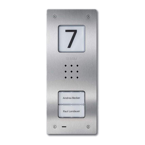
TLM 612-01
Door loudspeaker module for the
1+n system. The loudspeaker and
microphone are integrated, illumi-
nated light button, integrated door
release and light contact (Dr/Li).
Contact load max. 15 V AC/30 V
DC, 2 A, switching time for the door
release fixed at 3 seconds, switching
time for the light fixed at 0.8
seconds. Acoustic feedback when
actuating the call buttons.
TM 612-1 - TM 612-4
Call button module for wire-saving
1+n system.
1-4 call buttons, integrated LED
lighting, connection via terminal
block. Supply to the LED lighting via
terminal b and c with 12 V AC,
current consumption 25 mA per call
button module TM 612-... .
TLE 061-01
Custom fit door loudspeaker for the
1+n system. Integrated door release
and light contact (Dr/Li). Load max.
15 V AC / 30 V DC, 2 A. Connection
of customer's own call buttons (self
cleaning) via diode accessories
ZD 061-10, switching time for the
door release fixed at 3 seconds.
For optimum mounting in an
existing on-site communication
compartment, universal mounting
adapter ZTL 051-0 can be used.
ZD 061-10
Diode accessories for the connection
of max. 10 of the customer's own
call buttons by means of screw
terminals.
Additional ZD 061-... units can be
interconnected in order to connect
up to 500 call buttons to a custom-
fit door loudspeaker.
4 Device overview 1+n
Door loudspeakers, call buttons
11
4Appliance overview 1+n
Door loudspeakers
Siedle Classic
CL A 01 N - CL A 08 N
Door station with stainless steel
front, door loudspeaker and
illuminated call buttons.
Integrated door release and light
contact (Dr/Li). Contact load max.
15 V AC / 30 V DC, 2 A, switching
time for the door release fixed at
3seconds, switching time for the
light fixed at 0.8 seconds. Current
consumption LED lighting for the
bell buttons, 20 mA, 12 V AC each
per button.
Siedle Steel STL...
Door station with stainless steel
front, door loudspeaker and call
buttons. Integrated door release and
light contact (Dr/Li). Contact load
max. 15 V AC / 30 V DC, 2 A,
switching time for the door release
fixed at 3 seconds, switching time
for the light fixed at 0.8 seconds.
Current consumption LED lighting
for the bell buttons, 20 mA,
12 V AC each per button.
Siedle Classic
CL V 01 N-01 - CL V 04 N-01
Door station with stainless steel
front, door loudspeaker and
illuminated call buttons and camera.
Integrated door release and light
contact (Dr/Li). Contact load max.
15 V AC / 30 V DC, 2 A, switching
time for the door release fixed at
3seconds, switching time for the
light fixed at 0.8 seconds.
Current consumption LED lighting
for the bell buttons, 20 mA, 12 V
AC each per button.
Siedle Steel STL...
Door station with stainless steel
front, door loudspeaker, call buttons
and camera. Integrated door release
and light contact (Dr/Li). Contact
load max. 15 V AC / 30 V DC, 2 A,
switching time for the door release
fixed at 3 seconds, switching time
for the light fixed at 0.8 seconds.
Current consumption LED lighting
for the bell buttons, 20 mA,
12 V AC each per button.
12
4Appliance overview 1+n
Cameras
CMC 612-...
Colour camera module for the 1+n
system. Integrated 2-step heating
system, day/night switchover,
infrared lighting and video signal
transformer. Supply via the video
line rectifier VNG 602-... supply to
the heating 12 V AC, 100 mA.
Supply 20-30 V DC, current
consumption max. 120 mA.
CEC 612-...
External colour camera day/night
CCD video camera for external
mounting in weather proof housing,
wall arm with ball head and internal
wiring.
Supply via video line rectifier
VNG 602-..., 10.5–30 V DC, current
consumption max. 250 mA.
KA/WG 950-... C
Colour CCD video camera for
external mounting with weather
proof housing and sun shade, wall
arm with ball head and internal
wiring. Supply via video line rectifier
VNG 602-..., 20–30 V DC, current
consumption max. 250 mA.
Electronically controlled heating
system 12V AC/DC, 7 W. Using the
line rectifier foot accessory
ZNF 950-0 a 230 V AC supply is
possible.
13
4Appliance overview 1+n
Video distributor
VMO 511-2
Video distributor with amplifier,
1input, 1 output and 1 throughput
for integration in 70 mm junction
box or distributor mounting. This
amplifier is required if several
monitors are operated in one system
and the coaxial cable is laid as a side
circuit, e.g. in a multiple family
home. Supply 8-30 V DCmax. 25mA
Dimensions: 60 x 43 x 27 mm
VMO 602-4
Video distributor with 3 amplifiers.
1input, 3 outputs and 1 through-
put. For mounting in junction boxes
100 x 100 mm or in the distributor.
Is required for star-shaped
installation or for the configuration
of rising mains. Cast housing.
Supply 8-30 V DCmax. 90 mA
Dimensions: 94 x 62 x 30 mm
VKA 511-4
Camera switch for connecting
4video signal sources (4 video
cameras). 4 control inputs S1 - S4
for selection of the relevant input
E1 - E4. Supply 8-30 V DCmax.
55 mA
Dimensions: 94 x 62 x 30 mm
AW 101-...
Coaxial terminating resistor 75 Ohm,
0.5 W for video systems. In every
in-house telephone with colour
monitor HTSV/HTCV 811-...
throughput D is assigned a
terminating resistor in the
as-delivered status. When using
video distributors, unassigned
throughputs must be provided with
aterminating resistor.
GC 612-...
Group controller in 6-grid housing
for internal speech operation.
Connection of max. 6 in-house
telephones HTC/HTCV 811-... .
Calls can be made between the
connected in-house telephones.
8DIL switch for programming.
Supply 24 V DC, max. 300 mA
Max. contact load for secondary
signal unit 24 V, 2 A AC/DC
14
4Appliance overview 1+n
Power supply, line rectifiers
NG 602-...
Bus line rectifier in a 6-grid housing.
Primary: 230 V AC, 50/60 Hz
Secondary: 12 V AC, 1.6 A and
23.3 V DC - 0.3 A stabilized.
Supply to the 1+n system, door
release and lighting for the call
button modules.
VNG 602-...
Video line rectifier in a 10-grid
housing.
Primary: 230 V AC, 50/60 Hz
Secondary: 30 V DC, 1.1 A
stabilized.
For supply of the in-house
telephones with video and the video
camera.
TR 603-...
Transformer in a 3-grid housing.
Primary: 230 V AC, 50/60 Hz
Secondary: 12 V AC, 1.3 A.
Additional supply for lighting the call
button modules or door releases.
15
4Appliance overview 1+n
Controller
ETC 602-...
Storey controller in 6-grid housing
for connection to one or more storey
door stations. During a call from a
storey door station to an in-house
telephone, an additional call can be
routed from a main door station to
another in-house telephone.
Supply 24 V DC, max. 60 mA
CTÖ 602-...
Controller door release in a 3-grid
housing for actuation of a door
release which for safety reasons
should not be connected directly to
the door loudspeaker.
Door release time fixed at 3 seconds.
Supply 12 V DC, max. 70 mA
Max. contact load 24 V, 2A
NSC 602-...
Secondary signal controller for door
calls for connection of a secondary
signal unit with its own power
supply to HTS/HTC 811-… With 6
screw terminals; 3 for connection to
the side circuit installation,
3terminals as potential-free
switching contacts for door and
storey calls, max. 24 V, 1 A. To fit a
size 55-switch box under the in-
house telephone.
Protection system IP 20
Dimensions: 51 dia. x 23 mm
SFC 602-...
Switching/remote controller in 3-grid
housing for the execution of 4
switching/control functions. 1 relay
with changeover contact and 3
relays with 1 working contact each.
Actuation using buttons 1–6, light or
door release possible.
Supply 12 V DC, max. 250 mA
Max. contact load 24 V, 2A AC/DC
16
4Appliance overview 1+n
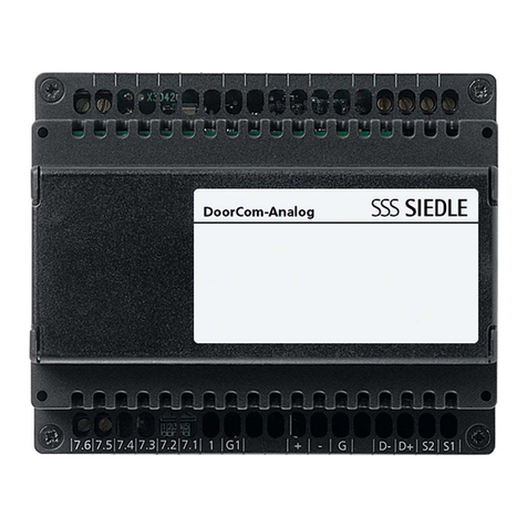
DoorCom
DCA 612-0
DoorCom-Analog for connection of
one or more door stations to an
analog PBX extension of a telephone
system. Up to 3 call buttons can be
connected. 12 V AC supply to
terminals b/c, connection to the 1+n
system using cores 1 and 7.1-7.3.
DCI 600-0
DoorCom-ISDN for link-up of one or
more door stations to the internal S0
bus of a telephone system. Up to 3
call buttons can be connected.
12 V AC supply to terminals b/c,
connection to the 1+n system using
cores 1 and 7.1-7.3.
VAR 602-...
Video interfacing relay in a 3-grid
housing for actuation of the camera
distributor VKA 511-4 when using
external cameras.
Supply 20–30 V DC, max. 60 mA.
Control voltage “Vc” 4-30 V DC,
max. 20 mA contact load (W0, W1,
W2) 12-30 V AC/DC, 2 A, protection
system IP20
Dimensions: 53.5 x 89 x 60 mm
ZR 502-...
Time relay ZR 502-0 in a 3-grid
housing with electronic control,
particularly suitable for use as a light
time switch with LED function
display, continuous light switch and
2potential-free changeover
contacts. Operating voltage 10–15 V
AC/DC control voltage 230 V AC
and/or 10–15 V AC/DC, galvanically
isolated
by optocouplers, OFF delay
adjustable from 15 seconds up to
12 mins. ±30%.
17
4Appliance overview 1+n
In-house telephones, accessories
HTS 811-0
Standard in-house telephone with
the functions:
•Calling, speech, door release and
storey call
•Door release and light button
•Rotary controller for ring tone
volume with integrated muting
•Door call as 3-tone call, storey call
as 2-tone call
•Call volume max. 83 dB (A)
HTC 811-0
Deluxe in-house telephone with the
functions:
•Calling, speech, door release and
storey call
•Door release and light button
•Rotary controller for ring tone
volume with integrated muting
•6buttons for switching and
control functions, of which two with
switchover facility as potential-free
buttons
•Internal speech communication
with GC 612-...
•2LEDs under the buttons to
display switching statuses
•Door call as 3-tone chime, storey
call as 2-tone call
•Call volume max. 83 dB A
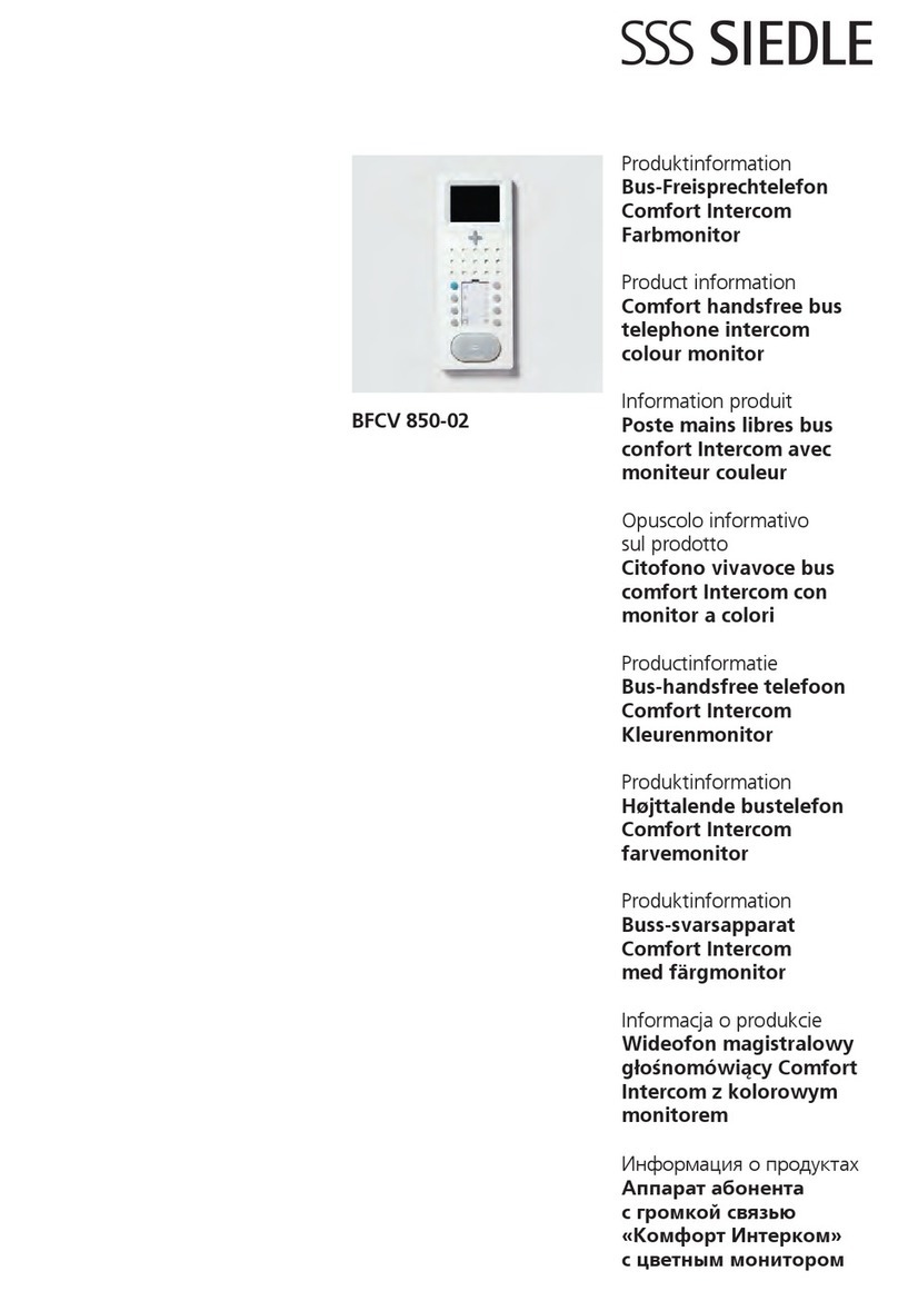
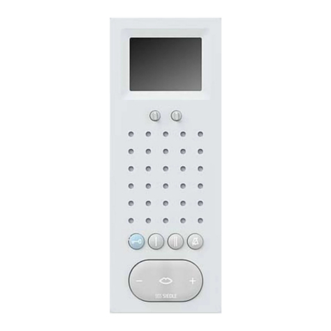
HTSV 811-...
Standard in-house telephone with
colour monitor
•Calling, speech, vision, door
release and storey call
•Colour monitor 6.3 cm (2.5")
•Door release and light button
•Rotary controller for ring tone
volume with integrated muting
•Monitor button for current picture
•Brightness and colour regulation
HTCV 811-...
Deluxe in-house telephone with
colour monitor
•Calling, speech, vision, door
release and storey call
•Colour monitor 8.8 cm (3.5")
•Integrated video memory for 28
pictures, upgradable with SD card
•Door release and light button
•6buttons for switching and
control functions, of which 2 with
switchover facility as potential-free
buttons
•Door call as 3-tone call, storey call
as 2-tone call
•Call volume max. 83 dB A
•Supply video 20–30 V DC, max.
200 mA
•Internal speech communication
with GC 612-...
•2LEDs under the buttons to
display switching statuses
•Rotary controller for ring tone
volume with integrated muting
•Monitor button for current picture
•5-way button for video memory
and zoom function
•Door call as 3-tone chime, storey
call as 2-tone call
•Call volume max. 83 dB A
•Supply video 20–30 V DC,
max. 200 mA
18
NS 711-...
Secondary signal unit to indicate
door and storey calls in large rooms
or corridors. Connection to the wire-
saving 1+n system. Call volume
steplessly adjustable up to max.
86 dB (A). Call differentiation for
door calls and storey calls.
ZTS 800-...
Standard table-top accessory for the
in-house telephone HTS 811-... .
Conversion from a wall to a table-
top unit. Connection of the table-
top unit to an 8-pin telecom socket
type UAE 8.
ZTC 800-...
Deluxe table-top accessory for the
in-house telephone HTC 811-... .
Conversion from a wall to a table-
top unit. Connection of the table-
top unit to an 8-pin telecom socket
type UAE 8 (8).
4Appliance overview 1+n
Accessories
ZTSV 811-...
Standard table-top accessory for the
in-house telephone HTSV 811-...
Conversion from a wall to a table-
top unit. Connection of a table-top
unit to an 8-pin UAE 8 (8) socket
type and a coaxial junction box.
ZTCV 811-...
Deluxe table-top accessory for the
in-house telephone HTCV 811-...
Conversion from a wall to a table-
top unit. Connection of a table-top
unit to an 8-pin universal telecom
8(8) junction box and a coaxial
junction box.
19
Door station installation
The door loudspeaker module
(TLM 612-... and call button module
TM 612-...) are each inserted in the
relevant terminal block. The circuit
diagram illustrates the two terminal
blocks of the TLM 612-... and
TM 612-...
When switching several doors in
parallel the terminal TLn must be
connected between the door
stations to allow synchronization
between the door loudspeakers.
The jumper of terminal + between
the door loudspeaker and call
button module must only be
inserted at one door station when
switching several doors in parallel.
Block diagram of door
loudspeaker module TLM 612-...
Terminals of the door loudspeaker
module TLM 612-...
•Potential-free light button T1/T2
•Door release contact c/Dr
•Light contact from telephone c/Li
•Vc actuation for video
•Terminal 6 call voltage
•Terminal 11 call current
recognition
•D+/D actuation for SFC 602-... /
CTÖ 602-...
•1reference terminal for 1+n
•TLn for synchronization of several
door stations
•+/– supply voltage 24 V DC
Block diagram of the call button
module
TM 612-1
•In the idle status, the in-house
telephone is supplied with power via
the terminal +.
•Potential-free call contact between
terminal 6 and 7.1
•The audio privacy device in the
door loudspeaker is actuated and
communication takes place via
terminal 11.
5Door station installation
20
5Installation
AS-Ta-64/1 Siedle-Vario

Other manuals for AS-Ta-64/1

1

This manual suits for next models

6

Other SSS Siedle Intercom System manuals

SSS Siedle BFCV 850-0 User manual

SSS Siedle

SSS Siedle BFCV 850-0 User manual

SSS Siedle ZERT 811-0 User manual

SSS Siedle

SSS Siedle ZERT 811-0 User manual

SSS Siedle BTLE 051-04 User manual

SSS Siedle

SSS Siedle BTLE 051-04 User manual

SSS Siedle BTSV 850-0 User manual

SSS Siedle

SSS Siedle BTSV 850-0 User manual

SSS Siedle Siedle Steel SK 600-0 User manual

SSS Siedle

SSS Siedle Siedle Steel SK 600-0 User manual

SSS Siedle BFS 850-0 User manual

SSS Siedle

SSS Siedle BFS 850-0 User manual

SSS Siedle HT 840-0 User manual

SSS Siedle

SSS Siedle HT 840-0 User manual

SSS Siedle AFSV 870-0 User manual

SSS Siedle

SSS Siedle AFSV 870-0 User manual

SSS Siedle IQ HTA User manual

SSS Siedle

SSS Siedle IQ HTA User manual

SSS Siedle BTCV 850-02 User manual

SSS Siedle

SSS Siedle BTCV 850-02 User manual

SSS Siedle Siedle Steel STLM 645-02 User manual

SSS Siedle

SSS Siedle Siedle Steel STLM 645-02 User manual

SSS Siedle Siedle Steel STLM/LL 611-02 User manual

SSS Siedle

SSS Siedle Siedle Steel STLM/LL 611-02 User manual

SSS Siedle SET CV 850-01 User manual

SSS Siedle

SSS Siedle SET CV 850-01 User manual

SSS Siedle MO 950-0/9 User manual

SSS Siedle

SSS Siedle MO 950-0/9 User manual

SSS Siedle Siedle BTS 850-0 User manual

SSS Siedle

SSS Siedle Siedle BTS 850-0 User manual

SSS Siedle SET 811-1 User manual

SSS Siedle

SSS Siedle SET 811-1 User manual

SSS Siedle AHT 870-0 User manual

SSS Siedle

SSS Siedle AHT 870-0 User manual

SSS Siedle HT 644-02 Installation manual

SSS Siedle

SSS Siedle HT 644-02 Installation manual

SSS Siedle BNS 750-02 User manual

SSS Siedle

SSS Siedle BNS 750-02 User manual

SSS Siedle HTV 840-0 User manual

SSS Siedle

SSS Siedle HTV 840-0 User manual

SSS Siedle BTC 850-02 User manual

SSS Siedle

SSS Siedle BTC 850-02 User manual

SSS Siedle BFSV 850-02 User manual

SSS Siedle

SSS Siedle BFSV 850-02 User manual

SSS Siedle VSS 711-01 User manual

SSS Siedle

SSS Siedle VSS 711-01 User manual

SSS Siedle A 150-10 User manual

SSS Siedle

SSS Siedle A 150-10 User manual

Popular Intercom System manuals by other brands

HM Electronics PRO850 installation instructions

HM Electronics

HM Electronics PRO850 installation instructions

Slinex MS-04 user manual

Slinex

Slinex MS-04 user manual

Viking Electronics K-1900-8-IP quick start guide

Viking Electronics

Viking Electronics K-1900-8-IP quick start guide

Escene IS750 Quick reference guide

Escene

Escene IS750 Quick reference guide

FARFISA INTERCOMS EX362 manual

FARFISA INTERCOMS

FARFISA INTERCOMS EX362 manual

Comelit HFX-700M Owner's manual installation and operation

Comelit

Comelit HFX-700M Owner's manual installation and operation

Vokkero SQUADRA 8 user guide

Vokkero

Vokkero SQUADRA 8 user guide

Comelit Magis 6401BC Technical manual

Comelit

Comelit Magis 6401BC Technical manual

Studio Technologies 374A user guide

Studio Technologies

Studio Technologies 374A user guide

Aiphone MYH-CUB Installation & operation manual

Aiphone

Aiphone MYH-CUB Installation & operation manual

Austdac ABMA3-1 user manual

Austdac

Austdac ABMA3-1 user manual

ESP BDeye user manual

ESP

ESP BDeye user manual

Entrotec PRO-AC4 Installation and setup guide

Entrotec

Entrotec PRO-AC4 Installation and setup guide

Bticino 308001 manual

Bticino

Bticino 308001 manual

Bpt HET/301 installation instructions

Bpt

Bpt HET/301 installation instructions

Aristel AN1808-08 operating manual

Aristel

Aristel AN1808-08 operating manual

Extel TALKLINE 10 Installation and user guide

Extel

Extel TALKLINE 10 Installation and user guide

Safeline IC2 Operation instructions

Safeline

Safeline IC2 Operation instructions

manuals.online logo
manuals.online logoBrands
  • About & Mission
  • Contact us
  • Privacy Policy
  • Terms and Conditions

Copyright 2025 Manuals.Online. All Rights Reserved.