manuals.online logo
Brands
  1. Home
  2. •
  3. Brands
  4. •
  5. SSS Siedle
  6. •
  7. Intercom System
  8. •
  9. SSS Siedle BTSV 850 Series User guide

SSS Siedle BTSV 850 Series User guide

System Manual
In-Home bus: Video
Issue 2010
2
Contents
1 In-Home bus: Video
System description 3
2 Safety remarks 3
3 Conguration,
conductor lengths
Single line system 4-5
Single line system
with bus distributor 6-7
Multiple line system 8-9
Calculation example 10
Installation with J-Y(ST)Y 11
Increased range operating mode 11
Bus distributor 12-13
4 In-Home: Video users
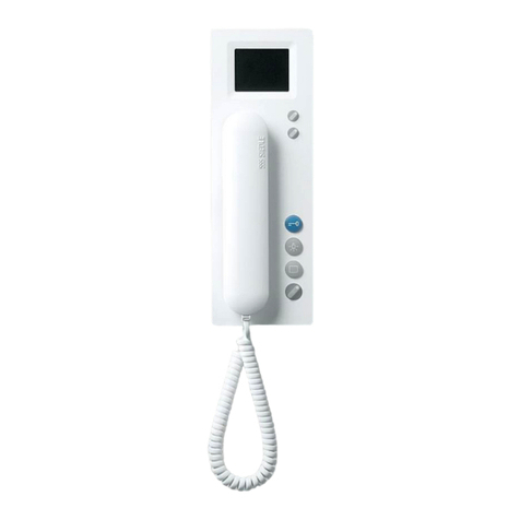
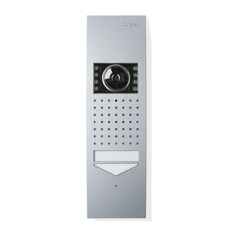
Bus door loudspeaker, call
buttons, bus video transmitter 14-15
Bus camera and accessories 16
Transformer, bus distributor 17
Power supply, line rectier 18
Switching and control functions 19
PC interface, Software,
DoorCom 20
Bus telephones audio 21-22
Bus telephones video 22-23
Accessories 24
Table top accessory 25
5 Video installation
Wiring diagrams AS
Bus call button module,
bus video line rectier 27
AS-TVHa-1/1 Siedle Vario
with S 850-0 28
AS-TVHa-1/1 Siedle Vario 30
AS-TVHa-1/1 Siedle Vario
with bus distributor
BVVU 650-... 32-33
AS-TVHa-1/1 Siedle custom-
t door loudspeaker 34
AS-TVHa-1/1 Siedle Classic 36
AS-TVHa-1/1 Siedle Select 38
AS-TVHa-1/1 Siedle Steel 40
AS-TVHa-1/1 Siedle Vario
with intercomfunction 42
AS-TVHa-1/2 Siedle Vario
2 door stations 44
AS-TVHa-2/1 Siedle Vario
multiple line system 46
AS-TVHa-1/1 Siedle Vario
calling via display call module 48
AS-TVHa-1/1 with Siedle Vario
DoorCom analog DCA 650-... 50
AS-TVHa-1/1 with Siedle Vario
additional external camera 52
6 Audio & video installation
wiring diagrams AS
AS-TVHa-1/1 Siedle Vario 54
AS-TVHa-1/2 Siedle Vario 2
audio & video door stations 56
AS-TVHa-2/1 Siedle Vario
multiple line system
audio & video 58
7 Programming - manual
Overview of functions 60
Remarks 64
Programming – manual
(Teach-In) 65
Door call to BTSV/BTCV 850-... 68
Door call to BFSV/BTCV 850-... 69
Door calls via the storey
call button 70
Door calls to several bus
telephones 71
Internal calls 72
Dialling the door station 74
Selection external camera 75
Call differentiation between
2 doors 76
Additional contact on the
BSM 650-... 78
Button of a bus telephone
on the BSM 650-... 79
Call button of a door station
on the BSE 650-... 80
Button of a bus telephone
on the BSE 650- 81
Bus secondary signalling
unit BNS 750-... 82
Door call via the display call
module DRM 611-... 83
Programming - Plug+Play
Basics 84
Programming - with PC
BPS 650-... and PRI 602-... USB 88
8 Supplementary functions
Switching and control functions 89
AS-TVHa-1/1 with switching
and control functions 90
Door release actuation 92
Parallel door call,
supplementary power supply,
video memory 94-95
Storey call parallel switching 96
Bus secondary signalling
unit BNS 750-... 96
Supplementary contact
for radio chime 97
Pilfer safeguard 97
Staircase/outside light 98
9 Servicing
As-delivered status
Power-On reset 99
Exchanging bus telephones 99
Exchanging BVSG 650-... 99
Operating modes 1-Norm-2 100
LED displays BVNG 650-0 101
Measured values 102
10 Glossary, index 103
3
1 In-Home bus: Video
System description
2 Safety remarks
Danger
Mounting, installation and
servicing work on electrical
devices may only be performed
by a suitably qualied electrician.
Failure to observe this regulation
could result in the risk of serious
damage to health or fatal injury
due to electric shocks.
When working at the device,•
observe the remarks relating to
mains cut-off.
Observe the DIN EN 60065•
standard! When establishing the
electronic connection, observe the
requirements of VDE 0805 or
EN 60950.
The building installation• must
include an all-pole mains switch
with a contact separation of at least
3 mm.
Ensure maximum fusing of 16A for•
the mains connection in the building
installation.
When planning large-scale•
(complex) systems, the distributor
space required for the switch panel
mounting devices must be taken
into consideration in the distributor
planning process.
No external voltages•
>30 V AC / DC may be applied to
bus users.
Devices with 230 V connection
In accordance with DIN VDE 0100
part 410, section 411.1.3 atten-
tion must be paid to ensuring a
safe separation between bus lines
and the mains voltage; i.e. bus and
mains cores must not be permitted
to touch! The bus line cable (extra-
low safety voltage) must be stripped
back by the minimum possible.
Siedle In-Home: Video
single line system
Conguration
The In-Home bus: Video features
the same basic structure as a Siedle
In-Home bus: Audio installation.
Here too, the installation comprises
a two-core line. The essential differ-
ence to the In-Home bus: Audio is
supplementary transmission of the
video signal to the cores.
Up to 31 different users can be con-
nected, e.g. bus telephones with
video, handsfree bus telephones
with video, door stations or devices
for switching and control functions.
Technically speaking, one device can
encompass several users.
If the building installation permits,
installation can be performed
between one bus telephone with
video and the next bus telephone
with video. If the building instal-
lation does not permit looping
through between bus telephones,
additional bus video distributors
must be used. Without a bus video
distributor, no nodes or branches are
permissible in the line.
In order to connect more than 31
users, several Siedle In-Home: Video
lines must be connected together.
Installation and programming
In their as-delivered status, the
devices are initially unprogrammed.
After initially switching on the bus
video line rectier, each of the con-
nected devices in the line is assigned
its own unique address.
Once installation is complete, a
mutual „teach-in“ process between
all the devices must be performed to
ensure that functions are correctly
executed (e.g. the bus telephone
rings as soon as the call button is
pressed).
Siedle In-Home: Video
multiple line system
Conguration
In-Home: Video single line system
is restricted to 31 users; In order to
connect more than 31 users, up to
15 lines can be coupled together.
Each line requires its own bus video
line rectier BVNG 650-0.
Installation and programming
The bus video line rectiers are con-
nected via two separate cores to
link the individual lines. Different
addresses must be set at the bus
video line rectiers using the rotary
switch.
Programming of the multiple line
system can be compared to the
single line system.
4
3 Conguration, conductor lengths
Single line system
Monitor branch max. 100 m/328 ft
Camera branch max. 100 m/328 ft
Conguration of In-Home: Video
The basic Siedle In-Home bus instal-
lation type is the single line system.
Within this one line, installation
takes place from one device to the
next, provided this is allowed by the
building installation.
In buildings with a side circuit and
individual branches into the apart-
ments, the bus video distributor
must be used. A maximum of 31
users are admissible within any one
line. Users are dened as devices
which occupy their own address
within the bus. If more than 31 users
are required, additional lines must be
congured. With only a few excep-
tions, all devices are assigned an
address. Up to 15 lines with 31 users
each can be congured.
Camera branch and monitor
branch
Within a line, a distinction is made
between the camera branch and the
monitor branch. Video door stations
are connected to the camera branch,
while bus telephones with video are
connected to the monitor branch. If
the installation requires an additional
monitor branch, so-called bus dis-
tributors must be used.
Users without video
In the case of In-Home: Video, audio
users can only be connected via a
bus audio decoupler BAA 650-... .
Switching and control devices are
also connected to the BAA 650-... .
Power supply
The nerve centre of every line is the
bus video line rectier, which con-
trols all the system functions. The
camera branch and monitor branch
are connected to it via separate
terminals.
Conductor material
Telecom or light current cables can
be used for the the installation:
J-Y(ST)Y twisted pair
conductors, shielded
A2Y(ST)2Y buried
telecommunication
cable
YR light current conductor
Core diameter 0.8 mm
The In-Home bus must be installed
on one pair of cores for J-Y(ST)Y
conductors, on two adjacent cores
for YR conductors.
Using J-Y(ST)Y conductors reduces
the likelihood of interference.
Conductor length
Conductor material YR cable with
0.8 mm diameter:
• max. 100 m from the bus video
line rectier to the most distant user
in the monitor branch
• max. 100 m from the bus video
line rectier to the most distant user
in the camera branch
With a core diameter of 0.6 mm, the
range is halved.
Within the line, the maximum
length of the conductor material
must not exceed 1,500 m.
When using J-Y(ST)Y conductor
material, longer ranges can be
achieved. Installation using J-Y(ST)Y
is described in detail on page 11.
When installing, ensure without fail
that the camera branch and monitor
branch are not laid in the same
cable. Forward and return lines to a
bus telephone with video must not
be laid in the same cable.
Otherwise, picture disturbance may
result.
If installation from one bus
telephone to the next bus telephone
is not possible, bus distributors must
be used. In this case, attenuation of
the conductor material and bus
distributors must be additionally
taken into consideration.
5
Terminating resistor
Transmission of signals within Siedle
In-Home: Video takes place using
high-frequency technology.
In order to avoid disturbance on the
bus cores, the end of each monitor
branch must terminated with an RC
element. The RC element comprises
a resistor with 100 Ohm and a
capacitor with 1 nF. In its as-
delivered status, each bus telephone
with colour monitor has a small
tted circuit board with this termi-
nating resistor at output terminals
TaM/TbM.
In-Home bus users: Video
Overview of user assignment of the
individual devices
Devices occupying 1 user
BTSV 850-...
BFSV 850-...
BTCV 850-...
BFCV 850-...
BTS 850-...
BFS 850-...
BTC 850-...
BFC 850-...
BNS 750-...
BSE 650-...
BEM 650-...
BSM 650-...
S 850-...
Devices occupying 2 users
BTLM 650-...
CL V xx B-...
CSV/STV/SBV 850-...
STL ...
BTLE 050-...
BVA 650-...
Devices with variable user assignment (depending on programming)
DCA 650-...
Devices occupying no users
BNG 650-...
BVNG 650-...
BAA 650-...
BVVU 650-...
BVVS 650-...
BIM 650-...
BCMC 650-...
BRMA 050-...
PRI 602-... USB
BVS 650-...
6
3 Conguration, conductor lengths
Single line system with bus distributor
Monitor branch 1, max. 100 m/328 ft
Monitor branch 2, max. 100 m/328 ft
Camera branch 1 max. 100 m/328 ft
Camera branch 2 max. 100 m/328 ft
Total attenuation max. 45 dB
Conductor length with bus
distributor
If the use of bus distributors is nec-
essary for installation, in addition to
the maximum range, attenuation of
the bus distributors and conductor
material must be additionally taken
into account.
The following information relating
to conductor lengths refers to one
camera branch and one monitor
branch. If several branches are
installed within a line, the informa-
tion is applicable to each branch.
Whichever value (attenuation or
conductor length) is reached rst is
applicable as a specication of the
admissible value.
Maximum conductor length
Conductor material YR cable with
0.8 mm diameter:
• max. 100 m from the bus video
line rectier to the most distant user
in the monitor branch
• max. 100 m from the bus video
line rectier to the most distant user
in the camera branch
• max. 45 dB attenuation from the
most distant user in the camera
branch to the most distant user in
the monitor branch
With a core diameter of 0.6 mm, the
range is halved.
The maximum admissible attenu-
ation is 45 dB within a line.
General rule for YR cable mate-
rial with 0.8 mm diameter:
10 m conductor length corre-
sponds to 2 dB attenuation!
The maximum length of the con-
ductor material to be laid within the
line is 1,500 m.
If the maximum admissible
attenuation of 45 dB is exceeded,
the bus video line rectier accessory
ZBVNG 650-0 must be used in the
BVNG 650-... to compensate for
this loss.
Signal transmission
Only signals from the In-Home bus
may be transmitted over the laid
conductor material. No additional
transmissions, for example PBX
extensions of a telephone system,
S0 Bus (ISDN) or data lines of an
alarm system in the same cable.
The camera branch and monitor
branch must be laid separately and
must not be located in the same
cable. This can result in disturbance
to the picture composition.
Terminating resistor
Transmission of signals within Siedle
In-Home: Video takes place using
high-frequency technology.
In order to avoid disturbance on the
bus cores, the end of each monitor
branch must terminated with an
RC element.
The RC element comprises a resistor
with 100 Ohm and a capacitor with
1 nF. In its as-delivered status, each
bus telephone with colour monitor
has a small tted circuit board with
this terminating resistor at output
terminals TaM/TbM.
7
3 Conguration, conductor lengths
Single line system with bus distributor and ZBVNG 650-0
Monitor branch 1, max. 100 m/328 ft
Monitor branch 2, max. 100 m/328 ft
Camera branch 1 max. 100 m/328 ft
Camera branch 2 max. 100 m/328 ft
Attenuation max. 55 dB
Conductor length with bus
distributor and ZBVNG 650-...
The ZBVNG 650-... accessory
amplies the video signal, so
permitting greater attenuation in the
camera branch and monitor branch.
To do this, the inserted jumper card
in the BVNG 650-... is removed and
the ZBVNG 650-... inserted in the
same slot.
The following information relating to
conductor lengths refers to a camera
branch or monitor branch. If several
branches are installed within a line,
the information is applicable to each
branch.
Whichever value is reached rst is
applicable as a specication of the
admissible value.
The limiting values must be adhered
to for each of the branches.
Maximum conductor length
Conductor material YR cable with
0.8 mm diameter:
• max. 100 m from the bus video
line rectier to the most distant user
in the monitor branch
• max. 100 m from the bus video
line rectier to the most distant user
in the camera branch
• max. 45 dB attenuation from the
bus video line rectier to the most
distant user in the camera branch
• max. 55 dB attenuation from the
bus video line rectier to the most
distant user in the monitor branch
With a core diameter of 0.6 mm, the
range is halved.
The maximum length of the
conductor material to be laid within
the line is 1,500 m.
8
3 Conguration, conductor lengths
Multiple line system
Most distant BVNG-BVNG (SaV/SbV) connection max. 100 m/328 ft
Monitor branch 1, max. 100 m/328 ft
Monitor branch 2, max. 100 m/328 ft
Camera branch 1 max. 100 m/328 ft
Camera branch 2 max. 100 m/328 ft
Attenuation max. 55 dB
Monitor branch max. 100 m/328 ft
Camera branch max. 100 m/328 ft
Line 1 Line 2 Line 15
9
Structure of a multiple line
system
A multiple line system comprises
individual lines which are linked
together by two cores. The lines are
connected at the bus video line
rectier using terminals SaV and SbV.
In multiple line systems, speech and
video connections are possible from
one line to another. To generate a
multiple line system, the bus line
rectier accessory ZBVG 650-... is
required in one of the bus video line
rectiers. In each bus video line
rectier, the bus video line rectier
accessory ZBVNG 650-... is required.
Differentiation between line 1
and line 2 ...
The lines are consecutively num-
bered using the address switch
“addr.” at the bus video line rectier
BVNG 650-... . Up to 15 lines can be
linked via the SaV and SbV cores.
The bus video line rectier is
connected via the bus distributor
BVVU 650-...
At the bus video line rectier, a
bus line rectier can be connected
directly via the cores Sa and Sb in
order to link a line with In-Home:
Audio. During installation, ensure
that each line is laid in a separate
cable.
Functions applicable across
individual lines
Door calls, selective door dialling and
switching and control functions can
also be used across individual lines.
Internal speech communication and
call forwarding between users is only
possible within a line.
Conductor length between the
lines
The admissible conductor lengths
within a line are identical to those
in a single line system. In addition,
the admissible conductor length
between the bus video line rectiers
must be taken into account.
This must be no more than 100 m
(45 dB) between the most distant
bus video line rectiers (YR cable
with 0.8 mm diameter).
In a multiple line system comprising
only 2 lines, connection between the
two bus video line rectiers is
possible without bus distributor
BVVU 650-... .
The maximum admissible lengths
within a line and the attenuation
values continue to be valid.
When installing, ensure without fail
that the camera branch and monitor
branch are not laid in the same
cable.
Forward and return video signal
looping must each be laid in a
separate cable.
Otherwise, picture disturbance may
result.
10
3 Conguration, conductor lengths
Example to determine the attenuation
BAA 650-...
0 dB
BVVU 650-...
1 dB
BVVU 650-...
1 dB
BVVU 650-...
1 dB
12 dB
7 m
5 m
5 m
5 m
12 dB
12 dB
25 m 11 m 4 m 4 m 12 m
Apartment 1
Apartment 2
Apartment 3
Apartment 4
Example to determine the atten-
uation with bus distributor
The system is installed using YR
cable 0.8 mm diameter. This means
that 10 m of conductor length have
an attenuation of 2 dB. Apartment 4
is decoupled using a bus audio
decoupler BAA 650-... , apartment 1
- apartment 3 are connected via bus
video distributor BVVU 650-... .
Attenuation in the camera
branch
Conductor length between the door
station and the sub-distributor 25 m.
25 m = 5 dB
Attenuation in the monitor
branch to apartment 3
Conductor length of the installation
cable. All values added, from the
bus video line rectier to the bus
telephone:
11 m + 4 m + 5 m = 20 m
20 m conductor length corresponds
to 4 dB attenuation!
Attenuation of the bus distributor
BVVU 650-... = 12 dB
Total value:
12 dB distributor + 4 dB conductor
= 16 dB
This means that apartment 3 has a
total attenuation from the camera to
the bus telephone of 16 dB + 5 dB
= 21 dB
Attenuation in the monitor
branch to apartment 1
Conductor length of the installation
cable. All values added, from the
bus video line rectier to the bus
telephone:
11 m + 4 m + 4 m + 12 m + 7 m
= 38 m
38 m of conductor material add up
to 7.6 dB
Attenuation of all bus distributors:
1 dB + 1 dB + 12 dB = 14 dB
Total value:
14 dB distributor + 7.6 dB conductor
= 21.6 dB
Apartment 1 has a total attenuation
from the camera to the bus tel-
ephone of 21.6 dB + 5 dB = 26.6 dB
The maximum value with this
example would be 26.6 dB from
the most distant video door station
to the most distant bus telephone,
the maximum admissible would be
45 dB.
With greater attenuation over 45 dB,
accessory ZBVNG 650-... can be
used to increase attenuation in the
camera branch to 45 dB and in the
monitor branch to 55 db.
On the following double page, the
precise function of the bus distrib-
utor is explained in detail.
11
3 Conguration, conductor lengths
Installation with J-Y(ST)Y, increased range
Installation with J-Y(ST)Y
The ZBVNG 650-... must be plugged
into the BVNG 650-...!
In deviation from the range
specication in standard systems
with YR cable material, when using
J-Y(ST)Y with 0.8 mm an increased
range is possible.
Conductor material J-Y(ST)Y cable
with 0.8 mm diameter:
• max. 150 m from the bus video
line rectier to the most distant user
in the monitor branch
• max. 150 m from the bus video
line rectier to the most distant user
in the camera branch
Increased range operating mode
The ZBVNG 650-... must be plugged
into the BVNG 650-...!
When using cable material J-Y(ST) Y
with 0.8 mm, it is possible to
increase the distance from the
bus video line rectier to the bus
telephones with colour monitor. In
this case, each bus telephone with
colour monitor must be provided
with an additional power supply
(e.g. video line rectier VNG 602-0).
At the bus video line rectier
BVNG 650-... the operating mode
switch must be set to 2.
Conductor material J-Y(ST)Y cable
with 0.8 mm diameter:
• max. 200 m from the bus video
line rectier to the most distant user
in the monitor branch
If it is necessary to use bus dis-
tributors within the installation, the
attenuation of the conductor
material and the bus distributor
must be taken into consideration.
With a core diameter of 0.6 mm, the
range is halved. Installation is also
possible in a multiple line system
with 0.8 mm conductor material.
In a multiple line system this
facility can be used to increase the
range in every line.
In the case of a parallel call to sev-
eral bus telephones with video, the
admissible conductor length of the
power supply must be noted. For
more information on supply and
parallel switching, see Chapter 8,
page 94.
The following still applies within
any one line: The maximum length
of the conductor material must not
exceed 1,500 m.
Installation is also possible in a
multiple line system with 0.8 mm
conductor material.
12
3 Conguration, conductor lengths
Bus distributor application
Camera branch: No bus distributor
required with a door station.
Monitor branch: No bus distributor
required when looping through from
bus telephone to bus telephone. The
integrated bus distributor in the bus
telephones is used.
Attenuation: No attenuation to be
considered.
BAA 650-... in the camera branch:
Connection of audio users (e.g.
BTLM 650-... or BTLE 050-...) or
users for switching and control
functions.
BAA 650-... in the monitor
branch: Connection of audio users
(BTS/BFS/BTC/BFC 850-...,
DCA 650-...) or users for switching
and control functions.
Attenuation: No attenuation to be
taken into consideration if
decoupled.
BVVS 650-... in the camera branch
More than one video door station
in the camera branch with “star
shaped” conductor routing.
BVVS 650-... in the monitor
branch: Within the In-Home bus:
Video more than one side circuit is
required.
Attenuation: The attenuation from
BVVS 650-..., BVVU 650-... and the
conductor length must be taken into
consideration.
BVVU 650-... in the camera
branch
More than one video door station
in the camera branch with “loop
through” conductor routing.
BVVU 650-... in the monitor
branch:
Connection of a bus telephone
with monitor to a side circuit with
“looped through” conductor
routing.
Attenuation: The attenuation from
BVVU 650-... and the conductor
length must be taken into consid-
eration.
Unconnected looping terminals in
the bus distributor BVVU 650-... and
BAA 650-... must always be termi-
nated with an RC element in order
to prevent disturbance to the bus.
13
3 Conguration, conductor lengths
Bus distributor attenuation values
BAA 650-... in the camera branch
BAA 650-... in the monitor branch
BVVS 650-... in the camera branch
BVVS 650-... in the monitor
branch
BVVU 650-... in the camera branch
BVVU 650-... in the monitor
branch
Application
Connection of a door station
without video (e.g. BTLM 650/
BTLE 050) or switching and control
devices (BSE 650-..., BSM 650-...,
BEM 650-...) at the Siedle In-Home
bus: Video.
For a connection example, see
page 56-57.
Application
Connection of pure audio users
(BTS/BFS 850-..., BTC/BFC 850-...,
DCA 650-...) or users for switching
and control functions (BSE 650-...,
BSM 650-..., BSE 650-...) within an
In-Home video bus.
For a connection example,
see page 54-55.
Application
When more than one video door
station is operated within a camera
branch.
For a connection example, see
page 44-45.
Application
When more than one rising
main/side circuit is required within
the Siedle In-Home bus. At the
outputs, additional distribution is
required via BVVU 650-... or
BAA 650-... Direct device connection
is not admissible.
Application
When more than one video door
station is operated within a line.
Application
Decoupling a video user from a side
circuit into the apartment.
For a connection example, see
page 32-33.
14
4 In-Home: Video users
Door loudspeakers, call buttons
BTLM 650-04
Bus door loudspeaker module for
In-Home bus. Loudspeaker and
microphone integrated, illuminated
light button, integrated door release
contact (DR) Acoustic acknowledge-
ment on pressing a button, can be
activated if required with the
BPS 650-... . contact load max.
15 V AC / 30 V DC / 2 A, switching
time DR xed at 3 seconds. Acoustic
feedback when actuating the call
buttons.
STV 850-...
Select video door station for surface
mounting with 1, 2 or 4 call buttons.
With the basic functions calling,
speech, vision and door release.
Illuminated light button. Connection
to Siedle In-Home bus: Video.
BTM 650-01 - BTM 650-04
Bus call button modules for In-Home
bus
1-4 call buttons, integrated LED
lighting. Connection by means of
ribbon cable to the bus door loud-
speaker. Supply to the LED lighting
via terminal b and c with 12 V AC,
current consumption 25 mA per bus
call button module BTM 650-...
SBV 850-0
Select letterbox video. Letterbox
with integrated video door com-
munication. Plastic housing with
solid aluminium front, for surface-
mounting. Removal from the front,
with newspaper compartment. In
compliance with DIN EN 13724.
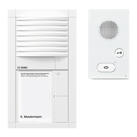
BTLE 050-03
Custom-t bus door loudspeaker
for In-Home bus. Integrated door
release contact (DR). Max. load
15 V AC / 30 V DC / 2 A.
Connection of existing call buttons
(self-cleaning) via bus call button
matrix BRMA 050-..., switching time
DR xed at 3 seconds. For optimum
mounting in an existing on-site com-
munication compartment, universal
mounting adapter ZTL 051-0 can
be used.
15
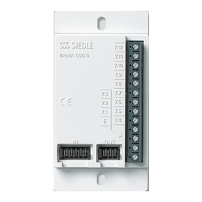
BRMA 050-01
Bus call button matrix for the con-
nection of existing call buttons to
the bus custom-t door loudspeaker
BTLE 050-...
Max. 160 call buttons can be con-
nected. However, a bus call button
matrix BRMA 050-... is required for
each started group of 12 call but-
tons.
BVA 650-... AP/UP
Bus video interfacing module for
actuation of external video cameras
without door station. Selective
dialling of the camera from a bus
telephone possible via a pro-
grammed button.
AP = Surface-mounted version
UP = Flush-mounted version
Siedle Classic
CL V 01 B-01 - CL V 04 B-01
Door station with stainless steel
front. Door loudspeaker and illu-
minated call buttons. Integrated
door release contact (DR), contact
load max. 15 V AC / 30 V DC / 2 A,
switching time DR xed at 3 sec-
onds. Current consumption for LED
lighting of bell buttons, per button
20 mA / 12 V AC. Acoustic feedback
when the call button is pressed.
BVS 650-01
Bus video transmitter in the surface-
mount housing with cable glands
for connection of an external video
camera to a bus door loudspeaker.
Is used, for instance, if a modular
camera is not possible or a custom-
t door loudspeaker BTLE 050-... has
to be equipped with video
surveillance.
Siedle Steel STL...
Door station with stainless steel
front, door loudspeaker, call but-
tons and bus camera. Integrated
door release contact (DR), contact
load max. 15 V AC, 30 V DC, 2 A,
switching time DR xed at 3
seconds. Current consumption LED
lighting for the bell buttons, 20 mA,
12 V AC each per button.
16
4 In-Home: Video users
Bus camera and accessories
BCMC 650-0
Bus colour camera module for Siedle
In-Home bus: Video. Integrated
2-step heating, day/night switching,
infrared lighting and video signal
converter. Supply via Siedle In-Home
bus: Video, heating supply 12 V AC,
100 mA.
VNG 602-02
Video line rectier in a 10-grid
housing.
Primary: 230 V AC, 50/60 Hz
Secondary: 30 V DC, 1.1 A
stabilized.
For additional power supply to
deluxe bus telephones when the
video memory module is used or for
power supply in case of parallel calls.
CEC 612-0
External colour camera day/night
CCD video camera for external
mounting in weather proof housing,
wall arm with ball head and internal
wiring.
Connection to In-Home bus: Video
via bus video interfacing module
BVA 650-... or bus video transmitter
BVS 650-... supply via additional
line rectier, 10,5 - 30 V DC, current
consumption max. 250 mA.
KA/WG 950-0 C
External colour CCD video camera
for external mounting with weather
proof housing and sun shade, wall
arm with ball head and internal
wiring.
Connection to In-Home bus: Video
via bus video interfacing module
BVA 650-... or bus video transmitter
BVS 650-... supply via additional line
rectier, 20 - 30 V DC, current con-
sumption max. 250 mA.
Using the line rectier foot acces-
sory ZNF 950-0 it is possible to pro-
vide a 230 V AC power supply.
17
4 In-Home: Video users
Bus distributor
TR 603-0
Transformer in a 3-grid housing.
Primary: 230 V AC, 50/60 Hz
Secondary: 12 V AC, 1.3 A
Supply to the LED lighting of the bus
call button module, door release or
heating for the bus camera
BCMC 650-...
BVVS 650-0
Symmetrical bus video distributor for
coupling/decoupling In-Home: Video
users, e.g. for the creation of rising
lines. Screw terminals for bus input
and 2x bus output.
BAA 650-0
Bus audio decoupling for connection
of audio users such as BFS 850-...,
BTS 850-..., BTC 850-...,
BFC 850-..., DCA 650-... or
switching and control devices within
In-Home: Video. Screw terminals for
bus input, looped bus throughput
and connection of audio users.
BVVU 650-0
Asymmetrical bus video distributor
for coupling/decoupling In-Home:
Video users. Screw terminals for bus
input, looped bus throughput and
bus output.
18
4 In-Home: Video users
Power supply, line rectiers
BVNG 650-0
Bus video line rectier in a 9-grid
housing.
Primary: 230 V AC, 50/60 Hz, door
release contact 15 V AC, 30 V DC,
2 A, switching time xed at 3
seconds. Light contact 15 V AC ,
30 V DC, 2 A, switching time
0.4 seconds, modication possible
using bus programming software
BPS 650-...
NG 602-01
Bus line rectier in a 6-grid housing.
Primary: 230 V AC, 50/60 Hz
Secondary: 12 V AC, 1.6 A and
23.3 V DC - 0.3 A stabilized.
For additional power supply to a
BTSV/BFSV/BTCV/BFCV 850-... in
case of parallel door calls.
ZBVG 650-0
Bus supply unit accessory as a
plug-in card for integration in bus
line rectier BNG 650-... or bus
video line rectier BVNG 650-... with
8-pin Western socket for connection
of the programming interface
PRI 602-... USB.
Is required in systems with more
than one line or for programming
the in-home bus via a Windows PC
and PRI 602-... USB. Only one unit
may be installed within the Siedle
In-Home bus.
ZBVNG 650-0
Bus video line rectier accessory
as a plug-in card for installation in
bus video line rectier BVNG 650-...
Required where attenuation within
a line is > 45 dB or for the creation
of a multiple-line system with more
than one BVNG 650-...
In the case of multiple line systems,
the ZBVNG 650-... must be installed
in each BVNG 650-...
19
4 In-Home: Video users
Switching, control
BSM 650-02
Bus switching module in 3-grid
housing. 4 integrated relays, each
with a potential-free working con-
tact. Actuation via the call buttons
of the bus telephones or light button
at the door station. Relay functions
as a timer between 0.4 seconds
and 12 seconds. Max. contact load
15 V AC, 30 V DC, 2 A. 12 V AC
supply required, 250 mA.
BIM 650-02
Bus interface module in switch
panel housing, used for connection
between Siedle Vario bus and Siedle
In-Home bus.
It is always required when a bus
door oudspeaker has to be equipped
with a COM 611-... or DRM 611-...
and call controller RC 602-... in
addition to or instead of direct call
buttons.
BSE 650-0
Bus switching unit for mounting in
70 mm boxes. LED for status display
and programming mode button.
Actuation via the call buttons of the
bus telephones or light button at the
door station. The relay functions as a
button, switch or timer for max.
19 min. 59 secs. Max. contact load
250 V AC / 6 A.
BVD 650-0
The bus video demodulator in a
6-grid switch panel housing converts
the video image at the bus cores
of the In-Home bus: video into a
standard FBAS video signal.
The converted video image can
subsequently be transmitted to any
video monitor or any TV with a suit-
able input or can be further
processed in a video system.
BEM 650-0
Bus input module for mounting in
a 55 junction box with an input for
tripping switching functions/trans-
mitting messages at the In-Home
bus.
Activation possible via potential-free
contact or 4 - 30 V DC, 10 mA.
For connection of BSM 650-...,
BSE 650-... and BEM 650-... to the
In-Home bus: Video,
the BAA 650-... is required.
20
4 In-Home: Video users
PC interface, DoorCom
PRI 602-0
Programming interface for
connection of a Windows PC via
serial interface to the Vario bus.
The Vario bus is programmed using
programming software PRS 602-...,
provided with the delivery. If the
BIM 650-... is additionally used, the
In-Home bus can also be
programmed.
DCA 650-02
DoorCom-Analog for connection of
one or more door stations to an ana-
logue PBX extension of a telephone
system. Up to 31 call numbers can
be stored.
The call can be made using bell
buttons or the display call module
from the door station. Power supply
with 12 V AC to terminals b and c,
connection to the In-Home: Video
only via BAA 650-...
PRI 602-01 USB
Programming interface for connec-
tion of a Windows PC via USB port
to the ZBVG 650-... interface. The
ZBVG 650-... is plugged into bus
line rectier BNG/BVNG 650-... .
Commissioning, programming and
servicing facility for the In-Home bus
using BPS 650-... software.
BPS 650-0 from V2.50
Bus programming software for
programming In-Home bus systems.
For this, the programming interface
PRI 602-... is also required in
conjunction with a BIM 650-... or
the PRI 602-0 USB.

This manual suits for next models

65

Other SSS Siedle Intercom System manuals

SSS Siedle CMC 612-01 User manual

SSS Siedle

SSS Siedle CMC 612-01 User manual

SSS Siedle BTS 850-02 User manual

SSS Siedle

SSS Siedle BTS 850-02 User manual

SSS Siedle CL 111 R-02 Series User manual

SSS Siedle

SSS Siedle CL 111 R-02 Series User manual

SSS Siedle HTC 811-0 User manual

SSS Siedle

SSS Siedle HTC 811-0 User manual

SSS Siedle CBCMC 650 Series User manual

SSS Siedle

SSS Siedle CBCMC 650 Series User manual

SSS Siedle VSS 711-01 User manual

SSS Siedle

SSS Siedle VSS 711-01 User manual

SSS Siedle NG 402-03 User manual

SSS Siedle

SSS Siedle NG 402-03 User manual

SSS Siedle SET CAB 850-1 User manual

SSS Siedle

SSS Siedle SET CAB 850-1 User manual

SSS Siedle CV 850-1 User manual

SSS Siedle

SSS Siedle CV 850-1 User manual

SSS Siedle BTLE 050-03 User guide

SSS Siedle

SSS Siedle BTLE 050-03 User guide

SSS Siedle BFSV 850-0 User manual

SSS Siedle

SSS Siedle BFSV 850-0 User manual

SSS Siedle Siedle Steel STLM/LL 611-02 User manual

SSS Siedle

SSS Siedle Siedle Steel STLM/LL 611-02 User manual

SSS Siedle Siedle Access Operating instructions

SSS Siedle

SSS Siedle Siedle Access Operating instructions

SSS Siedle BTS 850-02 User manual

SSS Siedle

SSS Siedle BTS 850-02 User manual

SSS Siedle SET CV 850-01 User manual

SSS Siedle

SSS Siedle SET CV 850-01 User manual

SSS Siedle ST 10-0 User manual

SSS Siedle

SSS Siedle ST 10-0 User manual

SSS Siedle AS-Ta-64/1 User guide

SSS Siedle

SSS Siedle AS-Ta-64/1 User guide

SSS Siedle SET VAB 850-1 User manual

SSS Siedle

SSS Siedle SET VAB 850-1 User manual

SSS Siedle AFSV 870-0 User manual

SSS Siedle

SSS Siedle AFSV 870-0 User manual

SSS Siedle STV 850-1 User manual

SSS Siedle

SSS Siedle STV 850-1 User manual

SSS Siedle SET CA 812 Series User manual

SSS Siedle

SSS Siedle SET CA 812 Series User manual

SSS Siedle CV 850-1-04 E User manual

SSS Siedle

SSS Siedle CV 850-1-04 E User manual

SSS Siedle IQ HTA User manual

SSS Siedle

SSS Siedle IQ HTA User manual

SSS Siedle BCV 850-1 User manual

SSS Siedle

SSS Siedle BCV 850-1 User manual

Popular Intercom System manuals by other brands

Fermax KIT VIDEO SALING Series manual

Fermax

Fermax KIT VIDEO SALING Series manual

Tropical Telecom 1820A Installer/user guide

Tropical Telecom

Tropical Telecom 1820A Installer/user guide

Videx 4000 Series Technical manual

Videx

Videx 4000 Series Technical manual

Motostar Livistar manual

Motostar

Motostar Livistar manual

Orcomm ORC–E1 installation manual

Orcomm

Orcomm ORC–E1 installation manual

Comelit Mini 6701 Technical manual

Comelit

Comelit Mini 6701 Technical manual

SilverCloud House 715 user manual

SilverCloud

SilverCloud House 715 user manual

FAAC FCI4000 installation instructions

FAAC

FAAC FCI4000 installation instructions

Comelit 2702W Technical manual

Comelit

Comelit 2702W Technical manual

Fermax SKYLINE VDS / BUS2 Installation and programming manual

Fermax

Fermax SKYLINE VDS / BUS2 Installation and programming manual

Renkforce 1373174 operating instructions

Renkforce

Renkforce 1373174 operating instructions

Aiphone WP100A Specifications

Aiphone

Aiphone WP100A Specifications

Auini AAW-68 Usage manual

Auini

Auini AAW-68 Usage manual

Dante BEATRICE Series manual

Dante

Dante BEATRICE Series manual

urmet domus AIKO 1716/1 quick start guide

urmet domus

urmet domus AIKO 1716/1 quick start guide

golmar Stadio Plus instruction manual

golmar

golmar Stadio Plus instruction manual

Bpt b-red VKW200 installation instructions

Bpt

Bpt b-red VKW200 installation instructions

urmet domus IPerCom VOG 7 1761 Series Instructions for use

urmet domus

urmet domus IPerCom VOG 7 1761 Series Instructions for use

manuals.online logo
manuals.online logoBrands
  • About & Mission
  • Contact us
  • Privacy Policy
  • Terms and Conditions

Copyright 2025 Manuals.Online. All Rights Reserved.