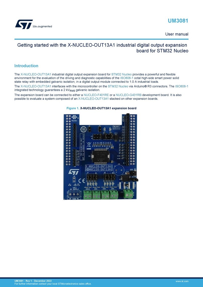
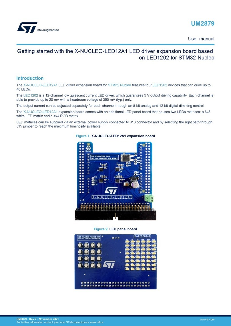
ST STM32 Nucleo User manual

March 2023 UM2365 Rev 3 1/22
1
UM2365
User manual
STM32 Discovery pack for LTE IoT cellular to cloud
Introduction
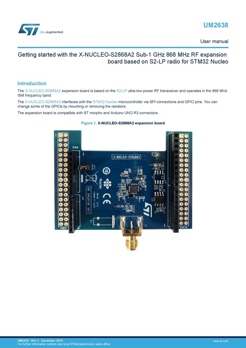
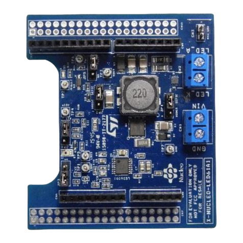
The STM32 Discovery pack for LTE IoT cellular to cloud (P-L496G-CELL02) is a turnkey
development platform for cellular and cloud technology-based solutions.
The pack contains an STM32L496AG-based low-power Discovery main board with
preloaded firmware and an STMod+ cellular LTE IoT worldwide expansion board with an
antenna.
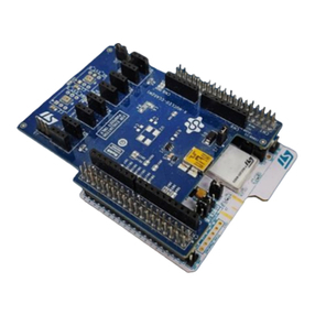
Figure 1. P-L496G-CELL02 (top view)
1. Picture is not contractual.
www.st.com

Contents UM2365
2/22 UM2365 Rev 3
Contents
1 Features . . . . . . . . . . . . . . . . . . . . . . . . . . . . . . . . . . . . . . . . . . . . . . . . . . . 6
2 Ordering information . . . . . . . . . . . . . . . . . . . . . . . . . . . . . . . . . . . . . . . . 7
3 Development environment . . . . . . . . . . . . . . . . . . . . . . . . . . . . . . . . . . . . 8
3.1 System requirements . . . . . . . . . . . . . . . . . . . . . . . . . . . . . . . . . . . . . . . . . 8
3.2 Development toolchains . . . . . . . . . . . . . . . . . . . . . . . . . . . . . . . . . . . . . . . 8
4 Conventions . . . . . . . . . . . . . . . . . . . . . . . . . . . . . . . . . . . . . . . . . . . . . . . . 9
5 Hardware layout and configuration . . . . . . . . . . . . . . . . . . . . . . . . . . . . 10
5.1 Board layouts . . . . . . . . . . . . . . . . . . . . . . . . . . . . . . . . . . . . . . . . . . . . . . 10
5.2 Cellular STMod+ expansion board . . . . . . . . . . . . . . . . . . . . . . . . . . . . . . .11
5.2.1 Modem power supply and reset . . . . . . . . . . . . . . . . . . . . . . . . . . . . . . . 12
5.2.2 SIM selection . . . . . . . . . . . . . . . . . . . . . . . . . . . . . . . . . . . . . . . . . . . . . 12
5.2.3 Modem firmware update. . . . . . . . . . . . . . . . . . . . . . . . . . . . . . . . . . . . . 12
5.3 Embedded ST_LINK/V2-1 . . . . . . . . . . . . . . . . . . . . . . . . . . . . . . . . . . . . 13
5.3.1 Drivers . . . . . . . . . . . . . . . . . . . . . . . . . . . . . . . . . . . . . . . . . . . . . . . . . . 13
5.4 Main board power supply . . . . . . . . . . . . . . . . . . . . . . . . . . . . . . . . . . . . . 13
5.4.1 Power supply sources . . . . . . . . . . . . . . . . . . . . . . . . . . . . . . . . . . . . . . 13
5.5 Main board reset sources . . . . . . . . . . . . . . . . . . . . . . . . . . . . . . . . . . . . . 14
5.6 Main board boot options . . . . . . . . . . . . . . . . . . . . . . . . . . . . . . . . . . . . . . 14
6 P-L496G-CELL02 troubleshooting . . . . . . . . . . . . . . . . . . . . . . . . . . . . . 16
7 P-L496G-CELL02 product information . . . . . . . . . . . . . . . . . . . . . . . . . 17
7.1 Product marking . . . . . . . . . . . . . . . . . . . . . . . . . . . . . . . . . . . . . . . . . . . . 17
7.2 P-L496G-CELL02 product history . . . . . . . . . . . . . . . . . . . . . . . . . . . . . . 18
7.3 Board revision history . . . . . . . . . . . . . . . . . . . . . . . . . . . . . . . . . . . . . . . . 18
8 Federal Communications Commission (FCC)
and ISED Canada (IC) Compliance Statements . . . . . . . . . . . . . . . . . . 19
8.1 FCC Compliance Statement . . . . . . . . . . . . . . . . . . . . . . . . . . . . . . . . . . . 19
8.2 ISED Compliance Statement . . . . . . . . . . . . . . . . . . . . . . . . . . . . . . . . . . 20

List of tables UM2365
4/22 UM2365 Rev 3
List of tables
Table 1. Ordering information . . . . . . . . . . . . . . . . . . . . . . . . . . . . . . . . . . . . . . . . . . . . . . . . . . . . . . . 7
Table 2. ON/OFF conventions . . . . . . . . . . . . . . . . . . . . . . . . . . . . . . . . . . . . . . . . . . . . . . . . . . . . . . 9
Table 3. STMod+ connector pin description . . . . . . . . . . . . . . . . . . . . . . . . . . . . . . . . . . . . . . . . . . . 11
Table 4. Boot settings . . . . . . . . . . . . . . . . . . . . . . . . . . . . . . . . . . . . . . . . . . . . . . . . . . . . . . . . . . . . 14
Table 5. Product history . . . . . . . . . . . . . . . . . . . . . . . . . . . . . . . . . . . . . . . . . . . . . . . . . . . . . . . . . . 18
Table 6. Board revision history . . . . . . . . . . . . . . . . . . . . . . . . . . . . . . . . . . . . . . . . . . . . . . . . . . . . . 18
Table 7. Document revision history . . . . . . . . . . . . . . . . . . . . . . . . . . . . . . . . . . . . . . . . . . . . . . . . . 21

UM2365 Rev 3 5/22
UM2365 List of figures
5
List of figures
Figure 1. P-L496G-CELL02 (top view). . . . . . . . . . . . . . . . . . . . . . . . . . . . . . . . . . . . . . . . . . . . . . . . . 1
Figure 2. Main board and expansion LTE IoT modem top view . . . . . . . . . . . . . . . . . . . . . . . . . . . . 10
Figure 3. Main board and expansion LTE IoT modem bottom view . . . . . . . . . . . . . . . . . . . . . . . . . 11
Figure 4. USB Composite Device driver installation. . . . . . . . . . . . . . . . . . . . . . . . . . . . . . . . . . . . . . 13

Features UM2365
6/22 UM2365 Rev 3
1 Features
•STM32L496AGI6 Arm®(a) Cortex®-M3 core-based microcontroller with 1 Mbyte of flash
memory and 320 Kbytes of RAM in a UFBGA169 package
•USB OTG HS
•On-board current measurement
•SAI audio codec
•ST-MEMS digital microphones
•8-Mbit PSRAM
•Two user LEDs
•User and reset push-buttons
•4-direction joystick with selection button
•Board connectors:
– 8-bit camera
– LCD flat cable
–USBMicro-AB
– Stereo headset jack including analog microphone input
– microSD™ card
– ARDUINO®Uno V3 expansion connector
– STMod+ expansion connector
•Board expansion features:
– Quectel BG96 worldwide cellular modem LTE Cat M1/Cat NB1/EGPRS module
300 kbps downlink, 375 kbps uplink
– Modem reset red LED and modem signaling green LED
– Switchable SIM interface: eSIM and micro SIM
– Pulse SMA antenna for frequency ranges: 824 / 900 / 1800 / 1900 / 2100 MHz. Might
this antenna not be suitable for your LTE band, use the Pulse SPDA24700 antenna
instead.
•Flexible power supply options: ST-LINK USB VBUS, USB connector, or external sources
•On-board ST-LINK/V2-1 debugger/programmer with USB re-enumeration capability:
mass storage, virtual COM port, and debug port
•Comprehensive free software libraries and examples available with the STM32Cube
MCU Package
•Support of a wide choice of Integrated Development Environments (IDEs) including IAR
Embedded Workbench®, MDK-ARM, and STM32CubeIDE
a. Arm is a registered trademark of Arm Limited (or its subsidiaries) in the US and/or elsewhere.

Development environment UM2365
8/22 UM2365 Rev 3
3 Development environment
3.1 System requirements
•Multi-OS support Windows®(a) 10, Linux®(b) 64-bit, or macOS®(c)
•USB Type-A or USB Type-C®to Micro-B cable
3.2 Development toolchains
•IAR Systems®- IAR Embedded Workbench®(d)
•Keil®- MDK-ARM(d)
•STMicroelectronics - STM32CubeIDE
a. Windows is a trademark of the Microsoft group of companies.
b. Linux®is a registered trademark of Linus Torvalds.
c. macOS®is a trademark of Apple Inc. registered in the U.S. and other countries.
All other trademarks are the property of their respective owners.
d. On Windows®only.

UM2365 Rev 3 9/22
UM2365 Conventions
21
4 Conventions
Table 2 defines some conventions used in the present document.
Table 2. ON/OFF conventions
Convention Definition
Jumper JPx ON Jumper fitted
Jumper JPx OFF Jumper not fitted
Jumper JPx [1-2] Jumper fitted between Pin 1 and Pin 2
Solder bridge SBx ON SBx connections closed by 0 Ωresistor
Solder bridge SBx OFF SBx connections left open
Resistor Rx ON Resistor soldered
Resistor Rx OFF Resistor not soldered

Hardware layout and configuration UM2365
10/22 UM2365 Rev 3
5 Hardware layout and configuration
Figure 2 illustrates the connection between the STM32L496AGI6-based Discovery main
board and the modem expansion board. The connection is done through the STMod+
connector.
5.1 Board layouts
There is no LCD with the STM32L496AGI6-based Discovery main board in this pack. For
the main board detailed description, refer to the user manual Discovery kit with
STM32L496AG (UM2160) at www.st.com.
Figure 2. Main board and expansion LTE IoT modem top view
MSv49532V2
STMod+ connector
LTE IoT modem
SMA antenna
STLINK USB
Main USB
Micro USB type AB for
firmware update
Embedded SIM
Red LED for modem
ready
Green LED for modem
signaling mode

UM2365 Rev 3 11/22
UM2365 Hardware layout and configuration
21
Figure 3. Main board and expansion LTE IoT modem bottom view
5.2 Cellular STMod+ expansion board
The expansion board is an LTE IoT modem based on the Quectel BG96 module. The BG96
is a series of LTE Cat M1/Cat NB1/EGPRS modules offering a maximum data rate of
300kbps downlink and 375kbps uplink. The connection with the STM32L496AGI6-based
Discovery main board is done through the STMod+ connector.
MSv48515V2
Micro SIM card socket
I2C EEPROM
Table 3. STMod+ connector pin description
STMod+ IOX=pin x Pin name Pin function
pin 1 CTSS Modem UART CTS
pin 2 RXDS Modem UART RXD
pin 3 TXDS Modem UART TXD
pin 4 RTSS Modem UART RTS
pin 5 GND Ground
pin 6 VCC +5V
pin 7 STMod+ IO7 I2C clock for EEPROM
pin 8 Sim_select1 Sim selection IO1 always set to 1
pin 9 PWRen Modem power enable

Hardware layout and configuration UM2365
12/22 UM2365 Rev 3
5.2.1 Modem power supply and reset
The cellular board is supplied through the 5V on the STMod+ connector (pins 6 and 15).
Pin 9 (power enable) activates the modem. A few seconds after this pin is driven, the red
LED is on to indicate that the modem is ready. The green LED starts flashing to indicate that
the modem is scanning for cell synchronization. At this time AT command can be sent using
UART.
If the power supply is not enough in signaling mode, the USB connector can provide an
additional power supply.
5.2.2 SIM selection
A switchable SIM interface is provided on the cellular modem board. The user selects either
the embedded SIM or the plastic SIM.
Set pin Sim_select0 to LOW to select the plastic SIM, or HIGH to select the embedded SIM.
5.2.3 Modem firmware update.
The modem firmware can be updated using the micro USB connector provided on the
modem:
1. First install the USB drivers of the modem from Quectel.
2. Install Qflash from Quectel and load the firmware.
3. Press start and reset the modem to download the firmware.
pin 10 I2C I2C data for EEPROM
pin 11 RIS Modem ring indicator RI
pin 12 RST Modem reset
pin 13 sim_CLK SIM clock
pin 14 DTRS Modem wake-up
pin 15 VCC +5V
pin 16 GND Ground
pin 17 Sim_RST Sim reset
pin 18 Sim_select0 Sim selection IO0, 0 for plastic SIM and 1 for
embedded SIM
pin 19 Sim_DATA Sim data
pin 20 STAS Modem status
Table 3. STMod+ connector pin description (continued)
STMod+ IOX=pin x Pin name Pin function

UM2365 Rev 3 13/22
UM2365 Hardware layout and configuration
21
5.3 Embedded ST_LINK/V2-1
The ST-LINK/V2-1 programming and debugging tool is integrated into the
STM32L496AGI6-based Discovery main board. Compared to ST-LINK/V2 the changes are
listed in Section 5.3.1.
5.3.1 Drivers
The ST-LINK/V2-1 requires a dedicated USB driver, available on www.st.com for Windows 7
and 8. On Windows XP, the ST-LINK/V2-1 driver requires WinUSB to be installed before
using the ST-LINK/V2-1. It is either available from the Microsoft website or included in the
USB driver for ST-LINK/V2 for XP.
When the STM32L496AGI6-based Discovery main board is connected to the PC before the
driver is installed, some STM32L496AGI6-based Discovery main board interfaces might be
declared as Unknown in the PC device manager. In this case, the user must install the driver
files, and update the driver of the connected device from the device manager.
Note: Prefer using the ‘USB Composite Device’ handle for a full recovery.
Figure 4. USB Composite Device driver installation.
5.4 Main board power supply
5.4.1 Power supply sources
The STM32L496AGI6-based Discovery main board can be powered by the following
sources:
•STLK from the ST-LINK/V2-1 USB connector CN5 with 500 mA current limitation
•Power mechanism of supplying the board by STLINK/V2-1
•Programing/debugging when the power supply is not from ST-LINK/V2-1
It is mandatory to power the board first using the user USB FS connector CN8 or the VIN pin
of ARDUINO®connector CN15 before connecting the USB cable from ST-LINK/V2-1 CN5
to the PC. Proceeding this way ensures that the enumeration succeeds using the external
power source.

Hardware layout and configuration UM2365
14/22 UM2365 Rev 3
The following power sequence procedure must be respected:
1. Put a jumper in JP3 at location U5V to use power from user USB CN8 or at location
E5V to use power from VIN of ARDUINO®connector CN15.
2. Connect the corresponding external power source.
3. Check that the green LED LD8 is turned ON.
4. Connect the PC to ST-LINK/V2-1 USB connector CN5.
If this order is not respected, the board might be powered by VBUS first from ST-LINK, and
the following risks might be encountered:
1. If the board requires more than 500 mA current, the PC might be damaged, or limit the
current. As a consequence, the board is not powered correctly.
2. The enumeration step requires 500 mA. Thus, there is a risk that the request is
rejected and enumeration does not succeed if the PC does not provide such current.
5.5 Main board reset sources
The reset signal of the STM32L496AGI6-based Discovery main board is active LOW and
the reset sources include:
•Reset button B1
•Embedded ST-LINK/V2-1, SW1 set to ON (default setting)
•ARDUINO®connector CN15 pin 3
5.6 Main board boot options
After reset, the microcontroller STM32L496AGI6 might boot from the 3 following embedded
memory locations depending on bits BOOT0 and BOOT1:
•Boot from the user flash memory
•Boot from the ICP (in-circuit programming)
•Boot from the SRAM
The selection of the memory space for the boot is done by two bits, BOOT0 and BOOT1.
A user option bit (bit[23], nBOOT1) defines the value of BOOT1. Specifically, when this bit is
set (put to 1), the empty flag status toggles and keeps this new status until the next OBL or
until a new set.
Table 4. Boot settings
nBOOT1
(OPTR[23])
nBOOT0
(OPTR[27])
BOOT0 pin
(PH3)
BOOT0 SW
configuration
OPTR[26])
Main flash
empty Boot memory space alias
XX010
User flash memory is aliased at
address 0x0000_0000
XX011
Test flash memory is aliased at
address 0x0000_0000
1X11X
Test flash memory is aliased at
address 0x0000_0000

UM2365 Rev 3 15/22
UM2365 Hardware layout and configuration
21
0X11X
Embedded SRAM is aliased at
address 0x0000_0000
11X0X
User flash memory is aliased at
address 0x0000_0000
10X0X
Test flash memory is aliased at
address 0x0000_0000
00X0X
Embedded SRAM is aliased at
address 0x0000_0000
Table 4. Boot settings (continued)
nBOOT1
(OPTR[23])
nBOOT0
(OPTR[27])
BOOT0 pin
(PH3)
BOOT0 SW
configuration
OPTR[26])
Main flash
empty Boot memory space alias

P-L496G-CELL02 troubleshooting UM2365
16/22 UM2365 Rev 3
6 P-L496G-CELL02 troubleshooting
On some P-L496G-CELL02, the BG96 modem might remain in test mode. Therefore, it is
necessary to put the modem in signaling mode to be able to connect to a cellular network for
the first time.
It concerns only the modems shipped with the following firmware revision:
BG96MAR02A05M1G
If the user is unable to connect to a cellular network with the BG96MAR02A05M1G
firmware, the AT command ‘AT+CFUN=1’ must be sent to the modem.
The user might run the demonstration software preloaded in the Discovery board to do that:
1. Open a terminal on the PC (Tera Term).
2. Connect the BG96 to the Discovery board.
3. Connect the Discovery board to the PC using the OTG FS USB connector CN8.
4. Reset the Discovery by pressing the reset button B1. Press the joystick UP button until
the following message appears to indicate that the user might send AT commands to
the BG96 modem:
– Welcome to STM32-Cellular to Cloud (STM32-C2C)
– AT commands terminal: connection to PC with USB-OTG FS is needed.
– Modem is using eSIM.
–RDY
– AT terminal ready... Press the joystick button to restart the AT terminal using the
micro SIM (if present).
–AT+CMEE=2
–OK
–ATE1
–OK
5. Verify the firmware revision by typing ‘at+cgmr’, if the firmware is
BG96MAR02A05M1G, follow the next step.
6. Put the modem in signaling mode by entering the command ‘AT+CFUN=1’, the modem
must respond OK.
7. Confirm that the modem is in signaling mode by entering the command ‘AT+CFUN?’,
the modem must respond +CFUN: 1.
8. This operation must be performed only once.

UM2365 Rev 3 17/22
UM2365 P-L496G-CELL02 product information
21
7 P-L496G-CELL02 product information
7.1 Product marking
The stickers located on the top or bottom side of all PCBs provide product information:
•First sticker: product order code and product identification, generally placed on the
main board featuring the target device.
Example:
•Second sticker: board reference with revision and serial number, available on each
PCB.
Example:
On the first sticker, the first line provides the product order code, and the second line the
product identification.
On the second sticker, the first line has the following format: “MBxxxx-Variant-yzz”, where
“MBxxxx” is the board reference, “Variant” (optional) identifies the mounting variant when
several exist, "y" is the PCB revision and "zz" is the assembly revision, for example B01.
The second line shows the board serial number used for traceability.
Parts marked as "ES" or "E" are not yet qualified and therefore not approved for use in
production. ST is not responsible for any consequences resulting from such use. In no event
will ST be liable for the customer using any of these engineering samples in production.
ST’s Quality department must be contacted prior to any decision to use these engineering
samples to run a qualification activity.
"E" or "ES" marking examples of location:
•On the targeted STM32 that is soldered on the board (for an illustration of STM32
marking, refer to the STM32 datasheet Package information paragraph at the
www.st.com website).
•Next to the evaluation tool ordering part number that is stuck or silk-screen printed on
the board.
Some boards feature a specific STM32 device version, which allows the operation of any
bundled commercial stack/library available. This STM32 device shows a "U" marking option
at the end of the standard part number and is not available for sales.
To use the same commercial stack in their applications, the developers might need to
purchase a part number specific to this stack/library. The price of those part numbers
includes the stack/library royalties.
Product order code
Product identification
MBxxxx-Variant-yzz
syywwxxxxx

P-L496G-CELL02 product information UM2365
18/22 UM2365 Rev 3
7.2 P-L496G-CELL02 product history
7.3 Board revision history
Table 5. Product history
Order
code
Product
identification Product details Product change
description Product limitations
P-L496G-CELL02
P-L496G-CELL02/
MCU:
– STM32L496AGI6
revision B
Initial revision No limitation
MCU errata sheet:
– STM32L496xx/4A6xx
device errata (ES0335)
Boards:
– MB1261-L496G-A01
(main board)
– MB1329-L496-B01
(cellular daughterboard)
PBL496GCEL2$AU1
MCU:
– STM32L496AGI6
revision B
– STM32L4 with LTE
cellular module
– Packaging: plastic blister
replaced by a carton box
– Removed SIM card
No limitation
MCU errata sheet:
– STM32L496xx/4A6xx
device errata (ES0335)
Boards:
– MB1261-CELL02-B06
(main board)
– MB1329-L496G-B03
(cellular daughterboard)
Table 6. Board revision history
Board reference Board variant and
revision Board change description Board limitations
MB1261
(main board)
MB1261-L496G-A01 Initial revision
No limitation
MB1261-CELL02-B06
Dedicated variant CELL02
was created for P-L496G-
CELL02 with replacement
of some EOL components.
MB1329
(cellular daughterboard)
MB1329-L496G-B01 Initial revision
No limitation
MB1329-L496G-B03 Removed some EOL
components

UM2365 Rev 3 19/22
UM2365 Federal Communications Commission (FCC) and ISED Canada (IC) Compliance State-
21
8 Federal Communications Commission (FCC)
and ISED Canada (IC) Compliance Statements
8.1 FCC Compliance Statement
Part 15.19
This device complies with part 15 of the FCC Rules. Operation is subject to the following two
conditions: (1) this device may not cause harmful interference, and (2) this device must
accept any interference received, including interference that may cause undesired
operation.
Part 15.21
Any changes or modifications to this equipment not expressly approved by
STMicroelectronics may cause harmful interference and void the user's authority to operate
this equipment.
Part 15.105
This equipment has been tested and found to comply with the limits for a Class B digital
device, pursuant to part 15 of the FCC Rules. These limits are designed to provide
reasonable protection against harmful interference in a residential installation. This
equipment generates uses and can radiate radio frequency energy and, if not installed and
used in accordance with the instructions, may cause harmful interference to radio
communications. However, there is no guarantee that interference will not occur in a
particular installation. If this equipment does cause harmful interference to radio or
television
reception, which can be determined by turning the equipment off and on, the user is
encouraged to try to correct the interference by one or more of the following measures:
•Reorient or relocate the receiving antenna.
•Increase the separation between the equipment and the receiver.
•Connect the equipment to an outlet on a circuit different from that to which the
receiver
is connected.
•Consult the dealer or an experienced radio/TV technician for help.
Note: Use only shielded cables.
Responsible party (in the USA)
Terry Blanchard
Americas Region Legal | Group Vice President and Regional Legal Counsel, The Americas
STMicroelectronics, Inc.
750 Canyon Drive | Suite 300 | Coppell, Texas 75019
USA
Telephone: +1 972-466-7845

Federal Communications Commission (FCC) and ISED Canada (IC) Compliance Statements
20/22 UM2365 Rev 3
8.2 ISED Compliance Statement
Compliance Statement
ISED Canada ICES-003 Compliance Label: CAN ICES-3 (B) / NMB-3 (B).
Déclaration de conformité
Étiquette de conformité à la NMB-003 d'ISDE Canada : CAN ICES-3 (B) / NMB-3 (B).
Other manuals for STM32 Nucleo
19
Table of contents
Other ST Computer Hardware manuals

ST
ST EVAL6470H-DISC User manual

ST
ST X-NUCLEO-IHM02A1 User manual

ST
ST ST7MDTU3-EMU2B User manual

ST
ST STR9 User manual

ST
ST STLINK-V3PWR User manual

ST
ST STEVAL-MKI015V1 Quick start guide

ST
ST X-NUCLEO-IDB04A1 User manual

ST
ST X-NUCLEO-IKS4A1 User manual

ST
ST X-NUCLEO-IHM13A1 User manual

ST
ST MotionTL User manual
Popular Computer Hardware manuals by other brands

Arctic
Arctic Accelero Twin Turbo 6990 installation manual

UNA AUTOMATION
UNA AUTOMATION URSULA HubBus installation manual

Alcad
Alcad 912 Series manual

Mellanox Technologies
Mellanox Technologies BridgeX BX4010 user manual

JYTEK
JYTEK PCI-69524 user manual

Phanteks
Phanteks GLACIER G3090Ti MSI installation guide