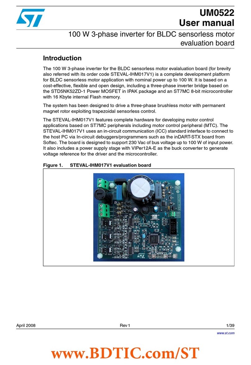
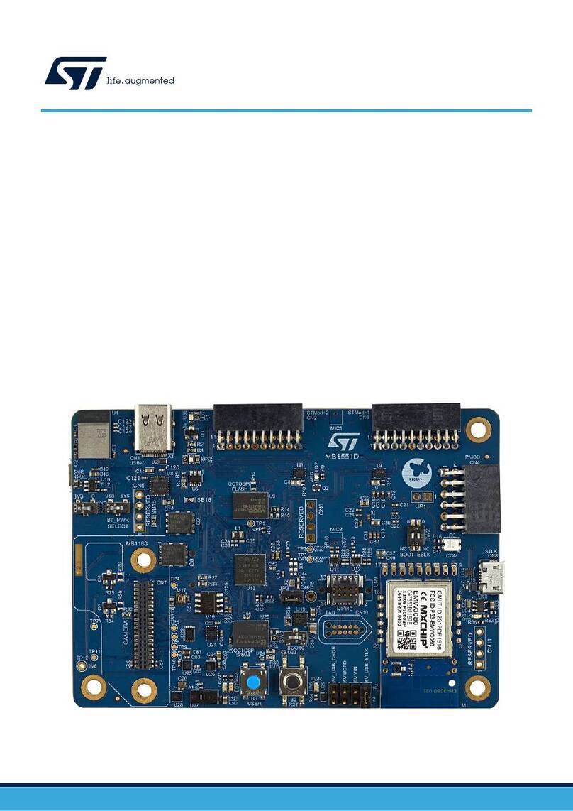
ST UM3019 User manual

Introduction
The FP-ATR-ASTRA1 is an STM32Cube function pack that implements a complete asset tracking application,
which supports long-range connectivity and short-range connectivity. This application reads the data from the
environmental and motion sensors, retrieves the geo-position from GNSS and sends them to the cloud using
Bluetooth® Low Energy and LoRaWAN connectivity.
The FP-ATR-ASTRA1 package supports low-power profiles and the related transitions to ensure long battery
autonomy. Moreover, it provides key features such as secure element management, the possibility to add custom
algorithms, debugging interfaces, and expansion capability.
The firmware is available as a standard source code .zip file.
Getting started with the STM32Cube function pack for IoT tracker node with
Bluetooth® Low Energy, LoRa, NFC connectivity, GNSS and sensors
UM3019
User manual
UM3019 - Rev 1 - April 2022
For further information contact your local STMicroelectronics sales office.
www.st.com

1FP-ATR-ASTRA1 software expansion for STM32Cube
1.1 Overview
The FP-ATR-ASTRA1 software package expands STM32Cube functionality.
The key features of the package are:
• Complete asset tracking firmware application to manage long-range connectivity (LoRaWAN) and short-
range connectivity (Bluetooth® Low Energy and NFC)
• Environmental and motion sensors management to monitor asset status
• Outdoor localization and geo-fencing based on a GNSS NMEA string available on Teseo-LIV3F
• Secure element personalization and certificate retrieving
• Power/battery management with low-power operating modes
• Flexible state machine to support different use cases
• Predefined customizable use cases:
– Fleet management
– Livestock monitoring
– Goods monitoring
– Logistics
– Custom
• Implementation available for the STEVAL-ASTRA1B
• Fully integrated in an end-to-end, proof-of-concept ecosystem, which includes:
– the DSH-ASSETRACKING web cloud dashboard
– the STAssetTracking mobile app available on Google Play and App Store
1.2 Architecture
FP-ATR-ASTRA1 is developed to support all the STEVAL-ASTRA1B functionalities.
The FP-ATR-ASTRA1, compliant with the STM32Cube architecture, is structured into a set of layers of increasing
abstraction.
The hardware abstraction layer (HAL) interfaces with the hardware. It provides the low-level drivers and the
hardware interface methods to interact with the upper layers (application, libraries, and stacks). It also provides
the APIs for the communication peripherals (I²C, SPI, UART, etc.) for initialization and configuration, data transfer,
and communication errors.
The package provides a board support package (BSP), which deals with the board-specific peripherals and
functions (LED, user button, etc.). The BSP structure follows the hardware structure, including a component
management layer as well as the specific layers of the board used. The modules included in the BSP are selected
according to the used hardware configuration.
The horizontal interaction among the layer components is handled directly by calling the feature APIs. The vertical
interaction with the low-level drivers is managed through specific callbacks and static macros implemented in the
library system call interface.
On top, the application layer contains functions and procedures that characterize the application and can be
changed by the end user.
UM3019
FP-ATR-ASTRA1 software expansion for STM32Cube
UM3019 - Rev 1 page 2/43

Figure 1. FP-ATR-ASTRA1 software architecture
FP-ATR-ASTRA1
abstraction
GNSS NMEA
Hardware
Dashboard
Parson
ST ASSET TRACKING
CLOUD DASHBOARD
Application
And
Middleware
Utilities
STM32Cube hardware abstraction layer (HAL)
ST WPAN
STEVAL-ASTRA1B
and
Mobile App ST ASSET TRACKING
APP
Sequencer
USB
BLE manager and
SDK v2
LOW POWER
Hardware
MANAGER
ST SAFE
1.3 Folder structure
The software package includes the following folders:
•Documentation: contains a compiled HTML file generated from the source code, which details the software
components and APIs.
•Drivers: contains the HAL drivers and the board-specific drivers for each supported board or hardware
platform, including the on-board components and the CMSIS vendor-independent hardware abstraction
layer for the Arm Cortex®-M processor series.
•Middleware: contains libraries and protocols for the USB communication, STM32-WPAN, GNSS NMEA,
Parson library, Bluetooth® Low Energy manager, STSAFE, sequencer, and low-power manager.
•Projects: contains sample application used to implement asset tracking examples.
This application is provided for the STEVAL-ASTRA1B evaluation kit with three development environments
(IAR Embedded Workbench for Arm, MDK-ARM, and STM32CubeIDE).
Figure 2. FP-ATR-ASTRA1 folder structure
1.4 APIs
Detailed technical information with full user API function and parameter description is in a compiled HTML file in
the “Documentation” folder.
UM3019
Folder structure
UM3019 - Rev 1 page 3/43

2Sample application description
A standard asset tracking routine acquires information about location, sensor and system status. Then, the
routine sends the information acquired through the available communication interfaces with the minimum power
consumption.
Different use cases require the customization of these routines in terms of:
• acquisition frequency
• sending interval
• algorithms to run in order to add specific features
• localization technologies
• communication interfaces
The FP-ATR-ASTRA1 offers the following preconfigured (and customizable) use cases:
1. fleet management
2. livestock monitoring
3. goods monitoring
4. logistics
5. custom
The characteristics of these use cases are listed in the table below.
Table 1. Use cases
Uses cases LoRa sending
interval
Bluetooth® Low Energy
sending interval
Indoor only
(GNSS disabled) Algorithm(1) Data logging(2)
Fleet management 40 s 100 ms N No Yes
Livestock monitoring 60 s 500 ms N Motion No
Goods monitoring 3600 s 200 ms Y Geofence Yes
Logistics 20 s 1000 ms N No Yes
Custom 30 s 400 ms N No Yes
1. Only an empty callback is available. It has to be filled by the user. See the manageAlgorithms( ) function in the source
code.
2. The “LOG” flag is available in the source code. The data logging is going to be available in the coming releases. See
AstraEngineParams_t typedef in the source code.
2.1 Firmware library structure
The FP-ATR-ASTRA1 firmware flexibility allows changing the operation mode easily. The state machine can
change states and transitions according to the selected use case.
The firmware library structure is modular to meet these requirements. The figure below shows how the data flow
from the input to the output.
UM3019
Sample application description
UM3019 - Rev 1 page 4/43

Figure 3. Data flow diagram
The data acquired from the sensors, GNSS, and ADC through the driver interface, are stored in the RAM and/or
EEPROM (the storage in the EEPROM is not implemented yet, but it is going to be available in the coming
releases). Then, they are processed and sent. The processing output can be sent as well. The same path is used
for the configuration channels, shown in the figure below, to manage the settings at runtime.
Figure 4. Configuration block diagram
2.2 State machine
The application flow evolves by using a state machine that triggers a status change depending on events and
triggers.
A simple state machine has been implemented featuring two states: full-run state and low-power state. These
states are not related to the MCU power state, but to the whole system condition. A minimum and a maximum
performance and, consequently, power consumption characterize these states. In the full-run state, everything is
on and all the data are sent to the dashboard. In the low-power state, all the components, except the MCU, are
configured in low-power mode.
The side button event triggers the transition between the two states. Another input can be a MEMS event output
or the result of an algorithm.
This is just an example of how a state machine can be implemented, changing the behavior of our device. Several
intermediate states can also be implemented, balancing the system responsiveness and the battery life.
UM3019
State machine
UM3019 - Rev 1 page 5/43

Figure 5. State machine-functional diagram
The figure below shows the detailed flow diagram of the process, referring to the code implementation.
Figure 6. State machine flow
UM3019
State machine
UM3019 - Rev 1 page 6/43

The states are:
•Start
•Run
•LP (low-power)
•End
Figure 7. State description
The following callbacks describe each state:
•StartXXXFn is the function that turns the module on in the start state;
•RunXXXFn is the function that executes the module in the run state (all the modules are running);
•LpXXXFn is the function that executes the module in the low-power state (GNSS, memory, and sensors are
turned off, while the other modules are in low power).
The events are:
•BP: button pressed event;
•SD: shutdown event;
•ER: error event;
•EP: automatic transition to next step;
•RN: go to full-run command
•LP: go to low-power command.
See the SM_APP.c file for further details.
2.3 HMI using LEDs and buttons
The STEVAL-ASTRA1B is provided with an RBG user LED and two user buttons:
• power/side button
• frontal button
UM3019
HMI using LEDs and buttons
UM3019 - Rev 1 page 7/43

Figure 8. STEVAL-ASTRA1B LEDs and buttons placement
The FP-ATR-ASTRA1B implements simple HMI functionalities using:
• the RGB LED, which turns:
– blue, if the configuration is ongoing
– red, if the sending is ongoing
– green:
◦ with slow blinking, if the Bluetooth® Low Energy is not connected
◦ with fast blinking, if the Bluetooth® Low Energy is connected
– yellow, if the Bluetooth® Low Energy is connected and sending
• the frontal button:
– short press: triggers asynchronous LoRa end data
– long press: system shutdown
• the side button:
– short press: changes the low-power status to run (or vice versa)
– long press: system reboot
UM3019
HMI using LEDs and buttons
UM3019 - Rev 1 page 8/43

3FP-ATR-ASTRA1 source code: relevant files
Despite the file tree complexity, only few files are involved in the application configuration of the use cases:
•App_astra.c
•Astra_confmng.c/.h
•Astra_sysmng.c/.h
•Astra_datamng.c/.h
•SM_APP.c/.h
Figure 9. Application files
3.1 App_astra.c
The app_astra.c file is the main file, that is, the entry point. It calls the initialization functions inside
MX_Astra_Init(). Specific defines allow disabling some blocks (for example, USE_XXXXXX).
The MX_Astra_Init() function is used for the system initialization:
•AstraSysInit();// → platform data initialization
•memory_init();
•sensor_init();
•gnss_init();
•stm32wl_init();
•stsafe_init();
UM3019
FP-ATR-ASTRA1 source code: relevant files
UM3019 - Rev 1 page 9/43

Figure 10. MX_Astra_Init() function
The MX_Astra_Process() function is used for the main loop:
•ASTRA_TASK_ID → the main sequencer task calls the process function related to each module:
–ManageMemory();
–ReadSensors();
–ReadGnss();
–stm32wl_process();
–stsafe_process();
UM3019
App_astra.c
UM3019 - Rev 1 page 10/43

Figure 11. MX_Astra_Process() function
The Init functions are implemented in the Astra_confmng.c/.h file and the process functions are implemented in
the Astra_datamng.c/.h file.
3.2 Astra_confmng.c/.h
This is the board configuration manager with the variables selected by the user to enable/disable each hardware
block and use case implementation and configuration.
UM3019
Astra_confmng.c/.h
UM3019 - Rev 1 page 11/43

Figure 12. How to select and configure use cases in the code
Refer to Astra_conf.h for:
•ASTRA ENGINE parameters;
• module usage parameters (USE_XXXX);
• generic info: MCU name, board name, firmware version string, etc.
3.3 Astra_datamng.c
In this file, the data gathered from the sensors and other inputs are stored in the RAM. They are ready to be
manipulated, for example, to run a specific algorithm on the data.
There is a globally accessible C structure, the AstraEngData, where the data are available anytime.
The data are acquired from each module:
• for example, stm32wl_process() for input/output on LoRa
•ReadSensors(); ManageSensorsEvents(); for sensor input
• saved in the RAM and/or EEPROM memory
•AstraEngData_t to store the latest acquired data
The AstraEngData_t structure is globally accessible.
The following code is used for the AstraEngData_t event data.
UM3019
Astra_datamng.c
UM3019 - Rev 1 page 12/43

typedef struct
{
struct
{
uint8_t bDebuggerEnabled:1;
uint8_t GNSS_NEW_DATA:1;
uint8_t ENVIRONMENTAL_NEW_DATA:1;
uint8_t POW_MAN_NEW_DATA:1;
uint8_t MEMS_EVENT_NEW_DATA:1;
uint8_t INERTIAL_NEW_DATA:1;
uint8_t bReserved7:1;
uint8_t bReserved8:1;
uint8_t bReserved8_16;
uint8_t bReserved116_24;
uint8_t bReserved124_32;
}c;
The following code is used for the AstraEngData_t sensor data.
struct
{
/* gnss */
float gnss_latitude;
float gnss_longitude;
float gnss_altitude;
int32_t gnss_sats;
uint8_t gnss_fix_validity;
/* sensors */
MOTION_SENSOR_Axes_t AccValue;
MOTION_SENSOR_Axes_t LPAccValue;
MOTION_SENSOR_Axes_t GyrValue;
float LPTempValue;
float PressValue;
float TempValue;
float HumValue;
MOTION_SENSOR_Event_Status_t LPAccInt;
MOTION_SENSOR_Event_Status_t AccInt;
The following code is used for the AstraEngData_t ADC data.
/* ADC */
uint16_t batteryVoltage;
uint16_t USBVoltage;
}d;
uint32_t nFwVersion;
} AstraEngData_t;
3.4 SM_APP.c/.h
These files contain the configuration structures of state machine.
See Section 2.2 for more details.
UM3019
SM_APP.c/.h
UM3019 - Rev 1 page 13/43

4STEVAL-ASTRA1B BlueST-SDK and Bluetooth® Low Energy
manager
The STEVAL-ASTRA1B acts as a Bluetooth® Low Energy peripheral. You can connect it via a Bluetooth® Low
Energy central entity, such as a smartphone, tablet, or industrial gateway.
The Bluetooth® Low Energy firmware implementation is simplified thanks to the BlueST-SDK. This SDK allows
the board to be recognized also in advertising mode, as the advertising packet has a specific structure and some
Bluetooth® Low Energy characteristics are preconfigured.
The main functionalities are:
• the data exchange;
• the debug console characteristic for the trace messages and textual human interaction;
• the extended configuration characteristic for the configuration data exchange in the json format.
These functionalities are available in the middleware through the APIs.
The BlueST-SDK enables the microcontroller firmware to advertise its capabilities and exchange data with mobile
applications as well as industrial gateways via Bluetooth® Low Energy. It is shared as an open-source code on
multiple Github repositories for Android, iOS, and Python.
The following figure shows the advertise frame format.
Figure 13. Advertise format
We assume that the mobile application (or the gateway), which receives the advertisement and needs to interpret
it, is able to translate the device ID and the firmware ID into a set of related properties. This can be achieved by
relying on a database.
The mapping among the device ID, the firmware ID, and the actual description of the firmware capabilities relies
on a json document.
There are maximum three option bytes available. The firmware developer can define their meaning to convey
different types of information. The developer also translates each byte and its meaning (for example, the mobile
application according to the mapping table defined in the json file).
UM3019
STEVAL-ASTRA1B BlueST-SDK and Bluetooth® Low Energy manager
UM3019 - Rev 1 page 14/43

4.1 STEVAL-ASTRA1B advertising packet
The STEVAL-ASTRA1B advertising packet includes the following options:
•ble_dev_id = 0x0C, where 0x0C = STEVAL-ASTRA1B
•ble_fw_id = 0x01 for the public firmware (Astra1 - Asset tracking)
•ble_fw_id = 0xFE for the development firmware
There are three option bytes:
• battery level percentage
•Enum String = Use case (for example, LOGISTICS, GOODS_MONITORING, etc.)
•Enum String = System Info (for example, Lora Joined, GNSS off, etc.)
Figure 14. STEVAL-ASTRA1B advertise
The STAssetTracking app adds other information, as soon as the board is recognized. The related information
is gathered from a json file downloaded from the web server (for example, firmware version, firmware name,
implemented characteristics, etc.).
4.2 Data exchange
The Bluetooth® Low Energy manager configures the device characteristics according to the data exchanged with
the Bluetooth® Low Energy master.
The STEVAL-ASTRA1B configured characteristics are:
UM3019
STEVAL-ASTRA1B advertising packet
UM3019 - Rev 1 page 15/43

• data:
– battery: battery data
– environmental: environmental data
– motion: motion data
• debug console:
– output trace messages from the application
– output errors from the application (error messages are highlighted among the traces)
– receive user textual input for human interaction (refer to Section 7 for USB commands and debug)
• extended configuration characteristic:
– configuration commands, exchanged in json format (for further details, see Section 6 )
UM3019
Data exchange
UM3019 - Rev 1 page 16/43

5LoRaWAN stack
The LoRaWAN stack runs on the STM32WL55JC microcontroller. The STM32WB5MMG drives the stack thanks
to the AT command master. The STM32WL55JC, instead, runs the AT-SLAVE firmware preloaded in the default
configuration of the STEVAL-ASTRA1B.
The STAssetTracking app can set the LoRaWAN keys through specific commands. The keys are stored in the
EEPROM (without KMS).
A simplified provisioning procedure through the STAssetTracking app automatically sets the needed keys to
register them on TTN V3 and on the DSH-ASSETRACKING dashboard.
The LoRaWAN frame payload is in Cayenne LPP format and consists of:
• pressure, temperature, and humidity
• accelerometer
• GNSS location
• analog and digital input
UM3019
LoRaWAN stack
UM3019 - Rev 1 page 17/43

6Using the STEVAL-ASTRA1B with the STAssetTracking app and the
DSH-ASSETRACKING dashboard
The STAssetTracking app supports all the features and Bluetooth® Low Energy custom commands implemented
in the FP-ATR-ASTRA1.
The app is available at Google Play and App store.
To allow the STEVAL-ASTRA1B board to join the LoRaWAN network, you need to use the STAssetTracking
together with the DSH-ASSETRACKING dashboard.
6.1 How to connect the STEVAL-ASTRA1B to a LoRaWAN network
You need a my.st.com account to install the STAssetTracking app. After the installation, follow the procedure
below to log on to the app and the DSH-ASSETRACKING dashboard.
UM3019
Using the STEVAL-ASTRA1B with the STAssetTracking app and the DSH-ASSETRACKING dashboard
UM3019 - Rev 1 page 18/43

Step 1. Register your device into your profile.
Figure 15. STEVAL-ASTRA1B registration (1 of 4)
Figure 16. STEVAL-ASTRA1B registration (2 of 4)
In this way, you automatically register the LoRAWAN device on the TTN V3 network server linked to
DSH-ASSETRACKING.
The STM32WB5MMG UID and the STM32WL55JC EUI are transmitted through Bluetooth® Low
Energy (for further details, see custom command parameters for keys).
UM3019
How to connect the STEVAL-ASTRA1B to a LoRaWAN network
UM3019 - Rev 1 page 19/43

Step 2. Insert your board name and click on the [ADD] button.
Figure 17. STEVAL-ASTRA1B registration (3 of 4)
Step 3. After the device registration is completed, refresh your device list to view the board just added and tap
on your board picture to connect it via Bluetooth® Low Energy.
Figure 18. STEVAL-ASTRA1B registration (4 of 4)
The STEVAL-ASTRA1B board can join the LoRaWAN network as soon as it is available. After joining, it
can start sending data to the dashboard.
The dashboard receives data from LoRa and Bluetooth® Low Energy with different acquisition
frequencies.
The smartphone stores the Bluetooth® Low Energy data before sending them to the dashboard.
UM3019
How to connect the STEVAL-ASTRA1B to a LoRaWAN network
UM3019 - Rev 1 page 20/43
Table of contents
Other ST Computer Hardware manuals
Popular Computer Hardware manuals by other brands

Simonds
Simonds CLP-274 Owners & safety manual

Seagate
Seagate Nytro 5350S NVMe SSD product manual

Avalue Technology
Avalue Technology ECM-TGUC user manual

PS Audio
PS Audio MultiWave II Installation and operation instructions

ekwb
ekwb EK-Quantum Vector FE RTX 3070 user guide

Cypress
Cypress CY62167DV18 Specification sheet