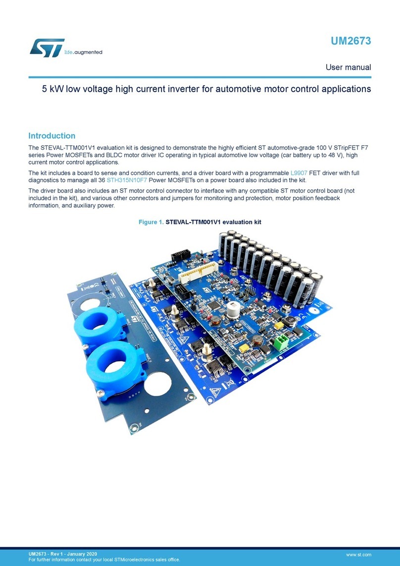
ST X-NUCLEO-53L7A1 User manual

Introduction
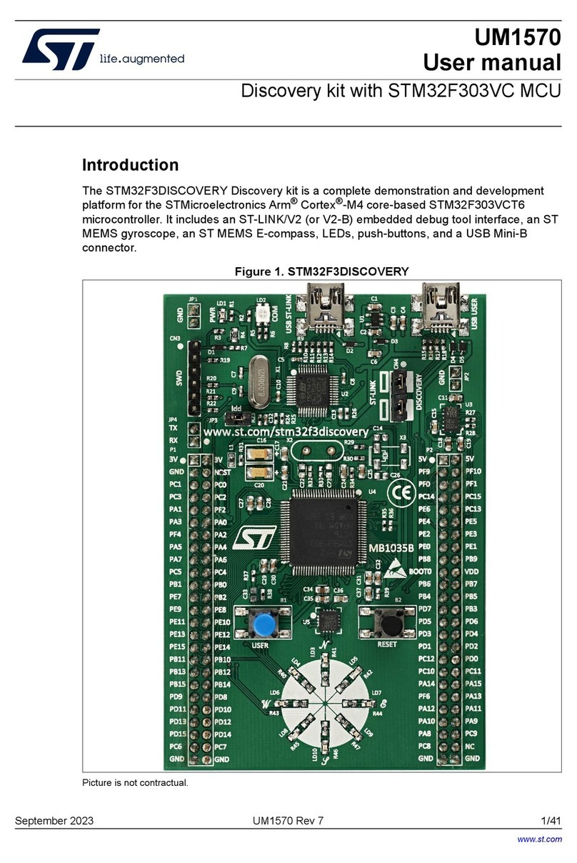
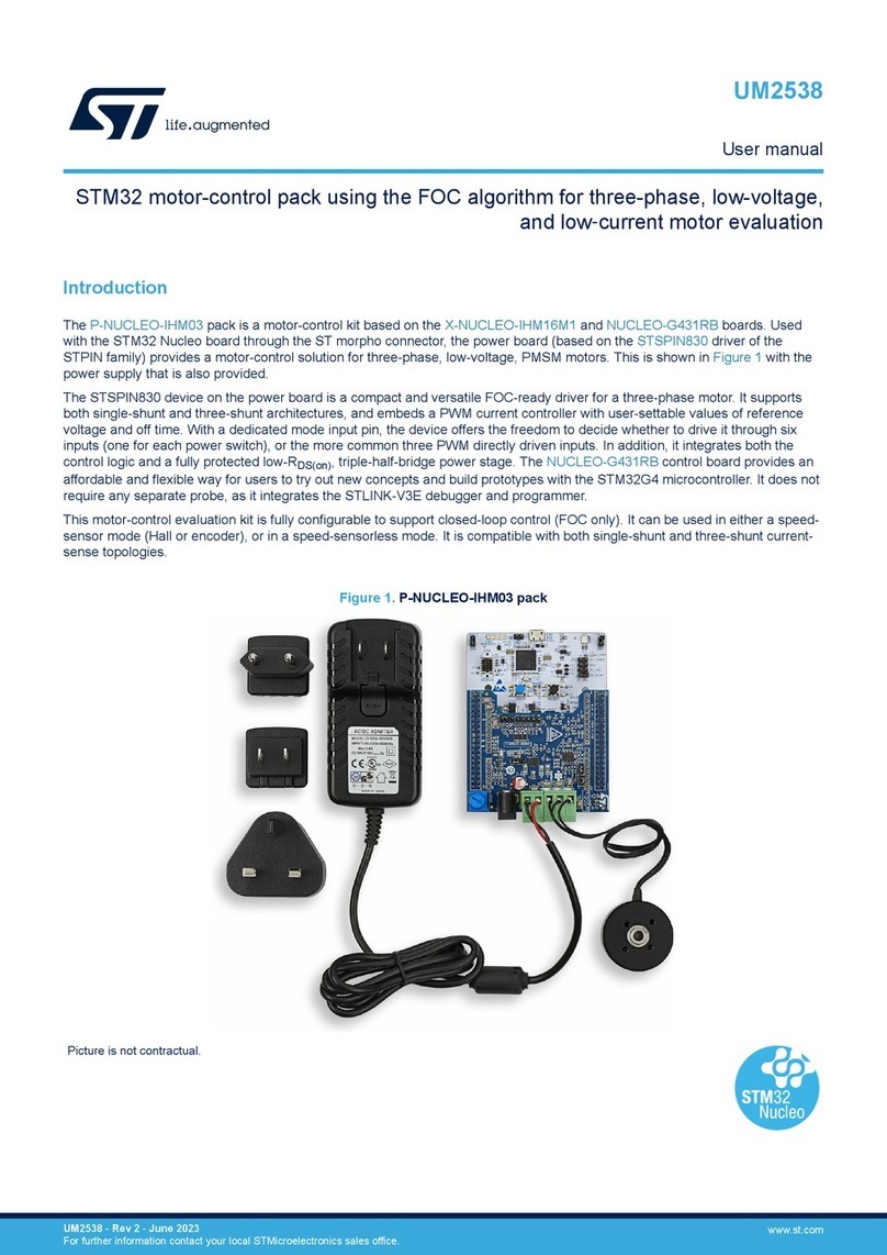
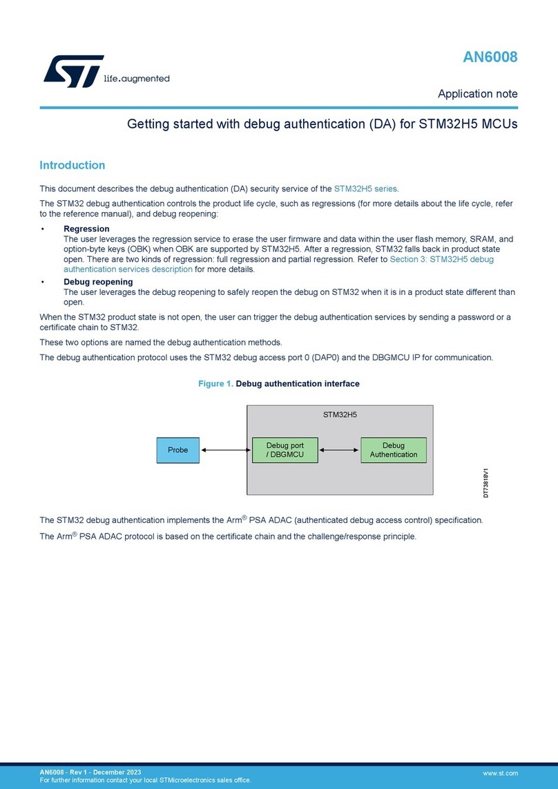
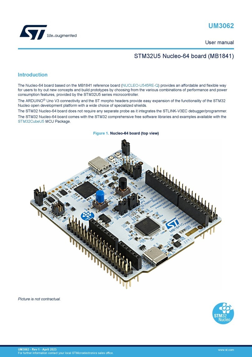
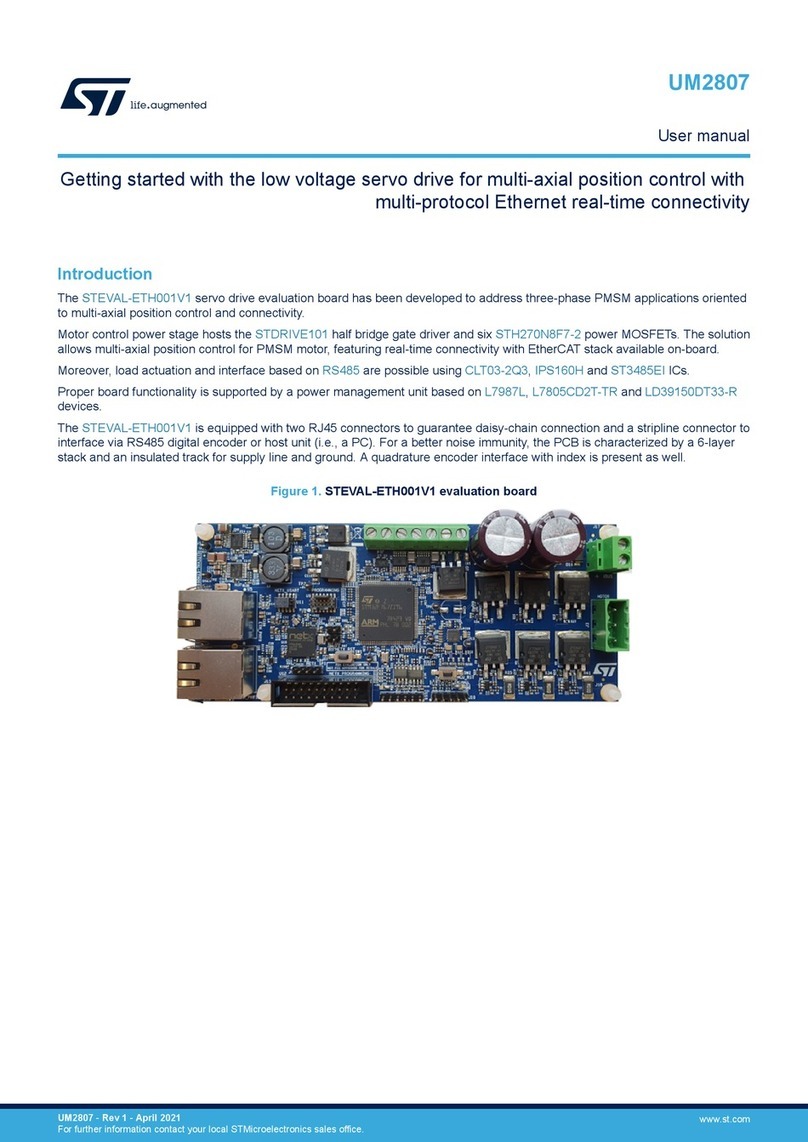
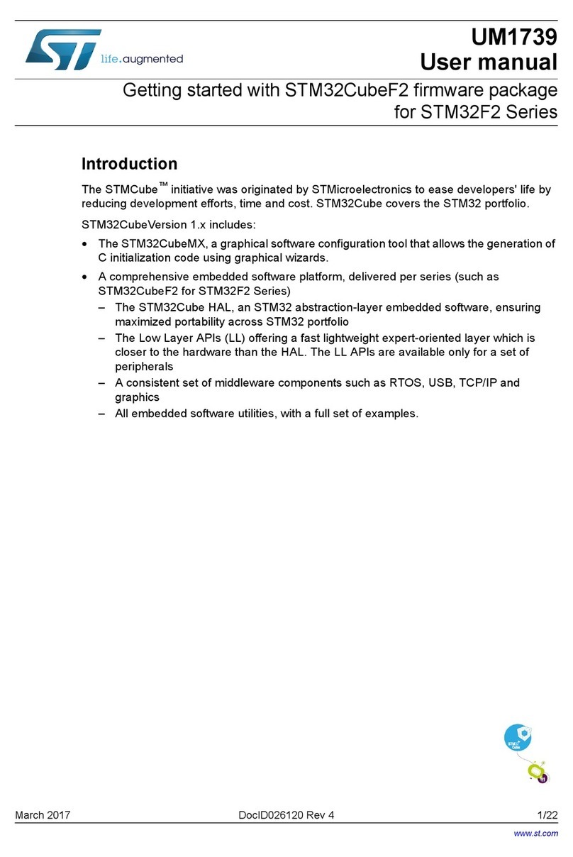
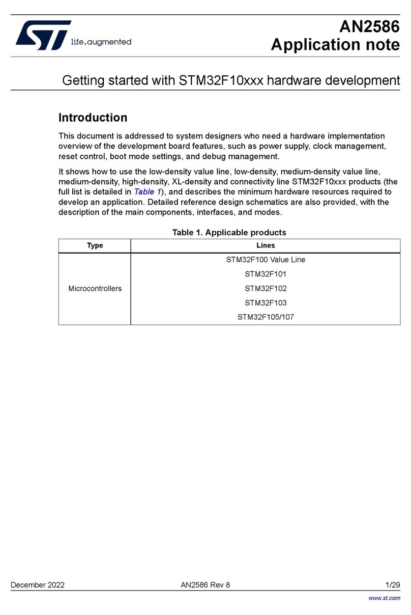
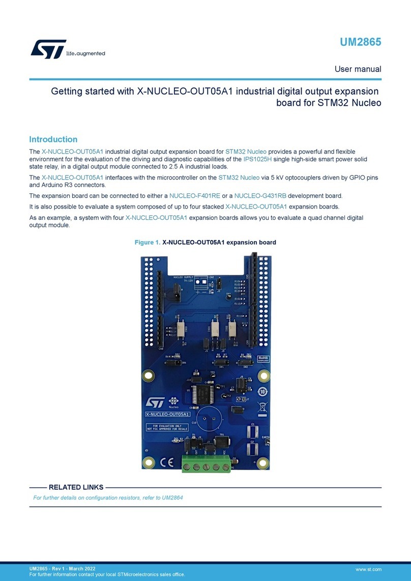
The X-NUCLEO-53L7A1 is an expansion board for any STM32 Nucleo development board equipped with the Arduino R3
connectors. It provides a complete evaluation kit that allows you to learn, evaluate, and develop applications using the
VL53L7CX Time-of-Flight 8x8 multizone ranging sensor with 90° FoV.
The expansion board is delivered with a cover glass holder in which you can fit three different spacers of 0.25, 0.5, and 1 mm
height below the cover glass to simulate various air gaps. A small oval cover glass fitting the sensor is included.
Several ST expansion boards can be stacked through the Arduino connectors, which allow, for example, the development of
VL53L7CX applications with Bluetooth or Wi-Fi interfaces.
Figure 1. X-NUCLEO-53L7A1 expansion board, spacers, cover glass holder, and oval cover glass
Getting started with the X-NUCLEO-53L7A1 expansion board for STM32 Nucleo
based on the VL53L7CX
UM3067
User manual
UM3067 - Rev 1 - October 2022
For further information contact your local STMicroelectronics sales office. www.st.com

1Getting started
1.1 Safety considerations
1.1.1 Electrostatic precautions
Warning: Take electrostatic precautions, including ground straps, when using the X-NUCLEO-53L7A1
expansion board. Failure to prevent electrostatic discharge could damage the device.
Figure 2. Electrostatic logo
1.1.2 Laser safety considerations
The VL53L7CX contains a laser emitter and the corresponding drive circuitry.
The laser output is designed to remain within Class 1 laser safety limits under all reasonable foreseeable
conditions, including single faults, in compliance with the IEC 60825-1:2014 (third edition).
The laser output remains within Class 1 limits as long as you use the STMicroelectronics recommended device
settings and respect the operating conditions specified in the data sheet.
The laser output power must not be increased and no optics should be used with the intention of focusing the
laser beam.
Figure 3. Class 1 laser product label
1.2 Features
•VL53L7CX Time-of-Flight 8x8 multizone ranging sensor with 90° FoV
• Accurate absolute ranging distance, independent of the reflectance of the target
• Up to 350 cm ranging
• Histogram-based technology
• Multiobject detection capability
• 0.25, 0.5, and 1 mm spacers to simulate air gaps
• One cover glass to protect the sensor from dust
• Compatible with STM32 Nucleo development boards
• Equipped with Arduino® UNO R3 connectors
• Full system software supplied, including code examples and graphical user interface
• RoHS, CE, UKCA, and China RoHS compliant
UM3067
Getting started
UM3067 - Rev 1 page 2/22

1.3 VL53L7CX Time-of-Flight sensor characteristics
• Laser wavelength: 940 nm
•Invisible laser radiation
• Maximum laser power emitted: 130 mW
• Integration time: 2 ms minimum
1.4 Spacers and covers
The X-NUCLEO-53L7A1 expansion board is delivered with:
•three spacers of 0.25 mm, 0.5 mm, and 1 mm height, used to simulate different air gaps between the
VL53L7CX and the rectangular-shaped cover glass;
• two nine-pin headers that allow connecting the two breakout boards to the X-NUCLEO-53L7A1 expansion
board.
Attention: The VL53L7CX is delivered with a liner to prevent potential foreign material from piercing the module holes
during the assembly process. Remove this liner before use.
1.5 Ordering information
Table 1. Ordering information
Order code Core product
X-NUCLEO-53L7A1 VL53L7CX
UM3067
VL53L7CX Time-of-Flight sensor characteristics
UM3067 - Rev 1 page 3/22

2Simplified schematic
Figure 4. X-NUCLEO-53L7A1 expansion board - simplified schematic
UM3067
Simplified schematic
UM3067 - Rev 1 page 4/22

3Using the expansion board
The X-NUCLEO-53L7A1 expansion board allows the user to test the VL53L7CX sensor functionality, to program it
and to understand how to develop an application using this sensor.
The X-NUCLEO-53L7A1 integrates:
• the VL53L7CX sensor;
• Arduino UNO R3 connectors;
• Connectors for SATEL-VL53L7CX optional breakout boards;
Important: Program a microcontroller to control the VL53L7CX through the I2C bus.
The application software and an example of the C-ANSI source code are available on the sensor web page.
The X-NUCLEO-53L7A1 expansion board can be connected to the STM32 Nucleo development board through
the Arduino UNO R3 connectors (CN5, CN6, CN8, and CN9) as shown in Figure 4.
UM3067
Using the expansion board
UM3067 - Rev 1 page 5/22

4Breakout boards
The X-NUCLEO-53L7A1 package does not include the VL53L7CX breakout boards.
You can purchase them in a pack of two PCBs as SATEL-VL53L7CX.
The X-NUCLEO-53L7A1 supplies the VL53L7CX breakout boards at 3.3 V (see Figure 4).
For mechanical integration purposes, it could be interesting to use the mini PCB by breaking the SATEL-
VL53L7CX along the red line as shown in the figure below. It is easier to integrate this setup into a customer's
device thanks to its small size.
Figure 5. SATEL-VL53L7CX
The SATEL-VL53L7CX boards can be directly plugged onto the X-NUCLEO-53L7A1 through the two 9-pin
headers (see Figure 6. SATEL-VL53L7CX breakout boards connected to the X-NUCLEO-53L7A1 expansion
board).
As an alternative, they can be connected to the X-NUCLEO-53L7A1 by using the mini PCB through flying wires
(see Figure 7).
UM3067
Breakout boards
UM3067 - Rev 1 page 6/22

Figure 6. SATEL-VL53L7CX breakout boards connected to the X-NUCLEO-53L7A1 expansion board
UM3067
Breakout boards
UM3067 - Rev 1 page 7/22

Figure 7. VL53L7CX mini PCB flying wire connection to the X-NUCLEO-53L7A1 expansion board
UM3067
Breakout boards
UM3067 - Rev 1 page 8/22

5Graphical user interface (GUI) and programming example for the
X-NUCLEO-53L7A1
To evaluate the VL53L7CX device performance, use the related GUI.
The X-NUCLEO-53L7A1 expansion board requires the NUCLEO-F401RE development board to use the GUI.
Important: Despite the fact that the X-NUCLEO-53L7A1 can be stacked on any STM32 Nucleo board equipped the Arduino
R3 connectors, the GUI is designed to work with the NUCLEO-F401RE only.
Download the GUI (in the Tools and Software tab of the X-NUCLEO-53L7A1 web page) to evaluate the
VL53L7CX.
UM3067
Graphical user interface (GUI) and programming example for the X-NUCLEO-53L7A1
UM3067 - Rev 1 page 9/22

6Schematic diagrams
Figure 8. X-NUCLEO-53L7A1 circuit schematic (1 of 5)
INT
LPn
SCL
SDA
I2C_RST
PWR_EN
Sensor.SchDoc
PWR_EN
INT
LPn
SDA
I2C_RST
SCL
Right
Satellite Connector.SchDoc
PWR_EN
INT
LPn
SCL
I2C_RST
SDA
Left
Satellite Connector.SchDoc
PA1
PA0
PA3
PA4
PA2
PA6
PA5
PA7
PA8
PA10
PA9
PC1
PC0
PC7
PB0
PB10
PB6
PB5
PB4
PB3
PB8
PB9
Host.SchDoc
3V3
R1
2.2k
R2
2.2k
UM3067
Schematic diagrams
UM3067 - Rev 1 page 10/22

Figure 9. X-NUCLEO-53L7A1 circuit schematic (2 of 5)
6.3V
C3
4.7uF
10V
C4
100nF
R4
47k
R7
47k
INT
SCL
SDA
LPn
I2C_RST
TP1
R6
47k
R5
47k
10V
C2
1uF
VIN
1
VSS
2
CE
3
NC
4
VOUT 5
U1
XC6222D331MR-G
PWR_EN
R3
47k
3V35V_NUCLEO
3V3
3V33V3
6.3V
C1
4.7uF
J1
2x1 2.54mmT/H
LK1
3V3_NUCLEO
J2
2x1 2.54mmT/H
LK2
3V3
GND
C1
RSVD3 C6
RSVD2 A7
RSVD1 A6
SDA
C3 RSVD5 C5
GND
C7
AVDD B1
AVDD B7
INT A3
RSVD6 C2
LPn
A5
IOVDD A4
SCL
C4
RSVD4 A2
I2C_RST
A1
THERMAL PAD
B4
U2
VL53L7CX
AVDD and IOVDD power supply for main sensor
Max Current = 60 mA + 90 mA = 150 mA
Power = 1.7 V x 150 mA = 255 mW
Satellite boards supplied directly from host power supplies
Jumpers for current measurement
UM3067
Schematic diagrams
UM3067 - Rev 1 page 11/22

Figure 10. X-NUCLEO-53L7A1 circuit schematic (3 of 5)
Nucleo Arduino Connectors
3V3_NUCLEO5V_NUCLEO
PB8
PB9
PC7
PB10
PB4
PB5
PA10
PA2
PA3
PA1
PA0
PA4
PB0
PC1
PC0
PA9
PB6
PA7
PA6
PA5
PB3
PA8
SSQ-110-03-F-S
1
2
3
4
5
6
7
8
9
10
CN5
10x1, 2.54mm, T/H
SSQ-108-03-F-S
1
2
3
4
5
6
7
8
CN6
8x1, 2.54mm, T/H
SSQ-108-03-F-S
1
2
3
4
5
6
7
8
CN9
8x1, 2.54mm, T/H
SSQ-106-03-F-S
1
2
3
4
5
6
CN8
6x1, 2.54mm, T/H
UM3067
Schematic diagrams
UM3067 - Rev 1 page 12/22

Figure 11. X-NUCLEO-53L7A1 circuit schematic (4 of 5)
INT
SCL
SDA
LPn
I2C_RST
PWR_EN
5V_NUCLEO3V3_NUCLEO
1
2
3
4
5
6
7
8
9J5_Left
9x1, 2.54mm, T/H
Figure 12. X-NUCLEO-53L7A1 circuit schematic (5 of 5)
INT
SCL
SDA
LPn
I2C_RST
PWR_EN
5V_NUCLEO3V3_NUCLEO
1
2
3
4
5
6
7
8
9J5_Right
9x1, 2.54mm, T/H
UM3067
Schematic diagrams
UM3067 - Rev 1 page 13/22

7Bill of materials
Table 2. X-NUCLEO-53L7A1 bill of materials
Item Q.ty Ref. Part/value Description Manufacturer Order code
1 0 R3 Not Fitted 47k, 0201, 1/20 W RES, 47k, 1%,
1/20W, 0201 Panasonic ERJ1GNF4702C
2 1 C4 Fitted 100nF, 0201, 10 V CAP, CER, 100nF,
10V, X5R, 0201 Murata GRM033R61A104KE15D
3 1 C2 Fitted 1uF, 0201, 10 V CAP, CER, 1uF,
10V, X5R, 0201 Samsung CL03A105KP3NSNC
4 1 CN5 Fitted -
CONN, HEADER,
10POS, SNGL,
2.54mm, T/H
Samtec SSQ-110-03-F-S
5 1 CN8 Fitted -
CONN, HEADER,
6POS, SNGL,
2,54mm, T/H
Samtec SSQ-106-03-F-S
6 1 U2 Fitted VL53L7CXV0GC/
1
Time-of-Flight 8x8
multizone ranging
sensor with wide
field of v
ST VL53L7CXV0GC/1
7 1 U1 Fitted SOT-25
IC, REG, LDO,
3.3V, 0.7A,
SOT25
Torex
Semiconductor XC6222D331MR-G
8 1 A1 Fitted PCB X-
NUCLEO-53L7A1 manufacturer PCB4132B
9 2 C1, C3 Fitted 4.7uF, 0402, 6.3 V CAP, CER, 4.7uF,
6.3V, X5R, 0402 TDK C1005X5R0J475K050BC
10 2 J1, J2 Fitted
CONN, HEADER,
2POS, 2.54MM,
T/H, VERT
Harwin M20-9990245
11 2
J5_Left,
J5_Right
Fitted
-
CONN, HEADER,
9POS, SNGL,
2.54mm, T/H
Samtec SSW-109-01-G-S
12 2 CN6, CN9
Fitted -
CONN, HEADER,
8POS, SNGL,
2,54mm, T/H
Samtec SSQ-108-03-F-S
13 2 R1, R2 Fitted 2.2k, 0402, 1/16
W
RES, 2.2k, 1%,
1/16W, 0402
Stackpole
Electronics RMCF0402FT2K20
14 2 LK1, LK2
Fitted -LINK, HEADER,
2.54MM Harwin M7571-05
15 4 R4, R5, R6,
R7 Fitted 47k, 0201, 1/20 W RES, 47k, 1%,
1/20W, 0201 Panasonic ERJ1GNF4702C
UM3067
Bill of materials
UM3067 - Rev 1 page 14/22

8Board versions
Table 3. X-NUCLEO-53L7A1 versions
PCB version Schematic diagrams Bill of materials
X$NUCLEO-53L7A1- (1) X$NUCLEO-53L7A1- schematic diagrams X$NUCLEO-53L7A1-bill of materials
1. This code identifies the X-NUCLEO-53L7A1 expansion board first version. It is printed on the board PCB.
UM3067
Board versions
UM3067 - Rev 1 page 15/22

9Regulatory compliance information
Notice for US Federal Communication Commission (FCC)
For evaluation only; not FCC approved for resale.
FCC NOTICE - This kit is designed to allow:
(1) Product developers to evaluate electronic components, circuitry, or software associated with the kit to
determine
whether to incorporate such items in a finished product and
(2) Software developers to write software applications for use with the end product.
This kit is not a finished product and when assembled may not be resold or otherwise marketed unless all
required FCC equipment authorizations are first obtained. Operation is subject to the condition that this product
not cause harmful interference to licensed radio stations and that this product accept harmful interference. Unless
the assembled kit is designed to operate under part 15, part 18 or part 95 of this chapter, the operator of the kit
must operate under the authority of an FCC license holder or must secure an experimental authorization under
part 5 of this chapter 3.1.2
Notice for Innovation, Science and Economic Development Canada (ISED)
For evaluation purposes only. This kit generates, uses, and can radiate radio frequency energy and has not been
tested for compliance with the limits of computing devices pursuant to Industry Canada (IC) rules.
À des fins d'évaluation uniquement. Ce kit génère, utilise et peut émettre de l'énergie radiofréquence et n'a pas
été testé pour sa conformité aux limites des appareils informatiques conformément aux règles d'Industrie Canada
(IC).
Notice for European Union
This device is in conformity with the essential requirements of the Directive 2014/30/EU (EMC) and of the
Directive 2015/863/EU (RoHS).
Notice for United Kingdom
This device is in compliance with the UK Electromagnetic Compatibility Regulations 2016 (UK S.I. 2016 No. 1091)
and with the Restriction of the Use of Certain Hazardous Substances in Electrical and Electronic Equipment
Regulations 2012 (UK S.I. 2012 No. 3032).
UM3067
Regulatory compliance information
UM3067 - Rev 1 page 16/22

Revision history
Table 4. Document revision history
Date Revision Changes
13-Oct-2022 1 Initial release.
UM3067
UM3067 - Rev 1 page 18/22

Contents
1Getting started ....................................................................2
1.1 Safety considerations ...........................................................2
1.1.1 Electrostatic precautions ...................................................2
1.1.2 Laser safety considerations.................................................2
1.2 Features ......................................................................2
1.3 VL53L7CX Time-of-Flight sensor characteristics ....................................3
1.4 Spacers and covers ............................................................3
1.5 Ordering information ............................................................3
2Simplified schematic ..............................................................4
3Using the expansion board ........................................................5
4Breakout boards...................................................................6
5Graphical user interface (GUI) and programming example for the X-NUCLEO-53L7A1
....................................................................................9
6Schematic diagrams ..............................................................10
7Bill of materials...................................................................14
8Board versions ...................................................................15
9Regulatory compliance information ...............................................16
Appendix A References ..............................................................17
Revision history .......................................................................18
List of tables ..........................................................................20
List of figures..........................................................................21
UM3067
Contents
UM3067 - Rev 1 page 19/22

List of tables
Table 1. Ordering information..................................................................3
Table 2. X-NUCLEO-53L7A1 bill of materials ...................................................... 14
Table 3. X-NUCLEO-53L7A1 versions ..........................................................15
Table 4. Document revision history ............................................................. 18
UM3067
List of tables
UM3067 - Rev 1 page 20/22
Other manuals for X-NUCLEO-53L7A1
1
Table of contents
Other ST Computer Hardware manuals

ST
ST STEVAL-MIC008A User manual

ST
ST EVALSPEAr320HMI User manual

ST
ST X-NUCLEO-NFC03A1 Parts list manual

ST
ST X-NUCLEO-53L7A1 User manual

ST
ST STM32F038 6 Series User manual

ST
ST MB467 User manual

ST
ST X-NUCLEO-USBPDM1 User manual

ST
ST X-NUCLEO-IDW01M1 User manual
ST
ST STM32G071B-DISCO User manual

ST
ST FP-ATR-ASTRA1 User manual

ST
ST X-NUCLEO-OUT10A1 User manual

ST
ST X-NUCLEO-IHM09M1 User manual

ST
ST AEK-COM-ISOSPI1 User manual

ST
ST X-NUCLEO-OUT16A1 User manual

ST
ST STM32Cube User manual

ST
ST X-NUCLEO-SRC1M1 User manual

ST
ST X-NUCLEO-OUT13A1 User manual

ST
ST QFN20 User manual

ST
ST X-NUCLEO-IHM09M2 User manual

ST
ST B-WB1M-WPAN1 User manual