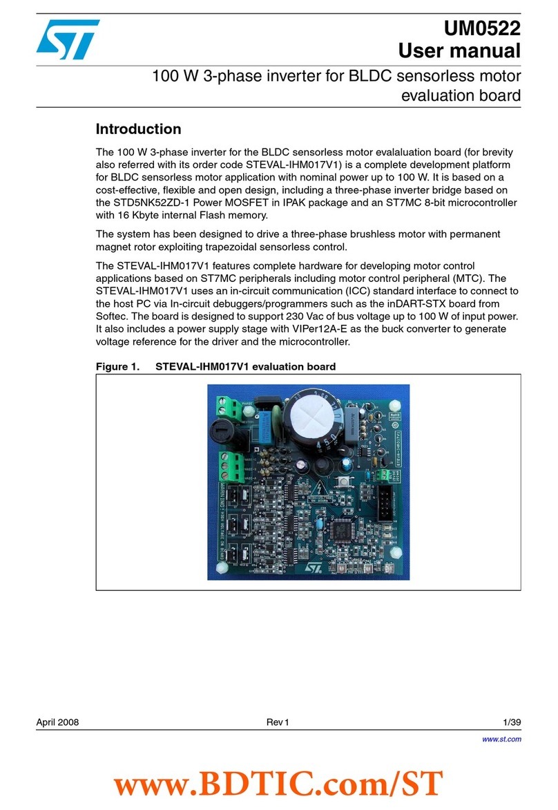
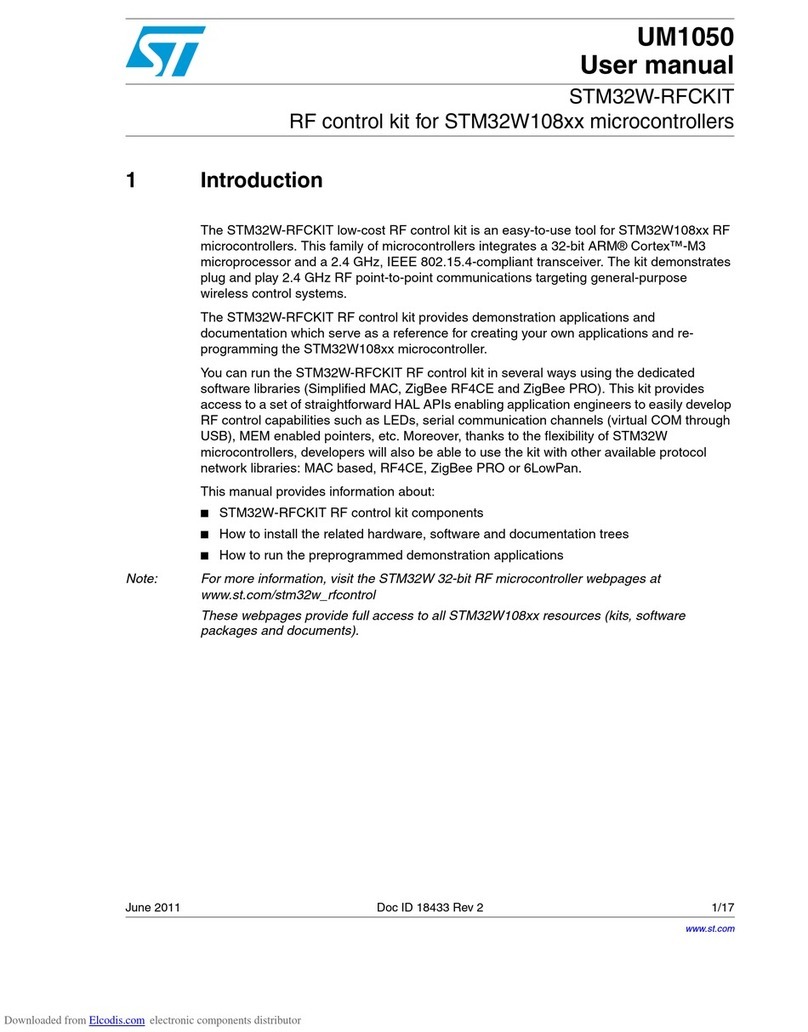
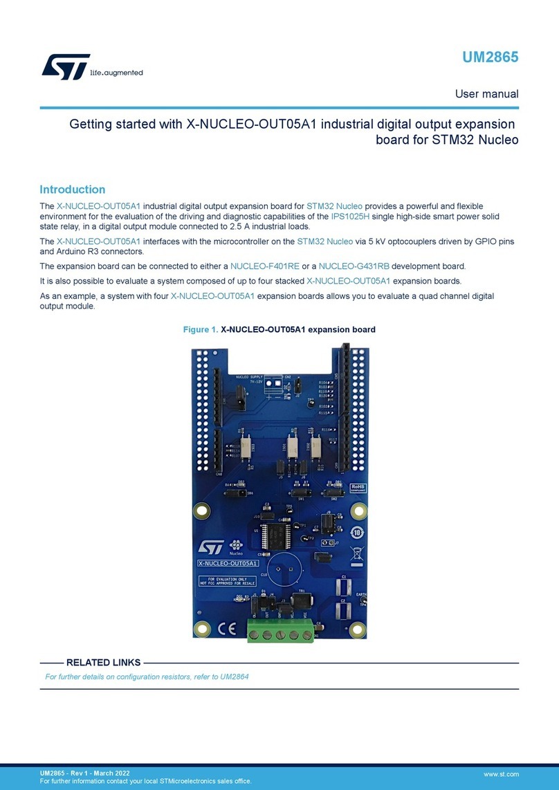
ST X-STM32MP-MSP01 User manual

Introduction
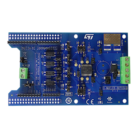
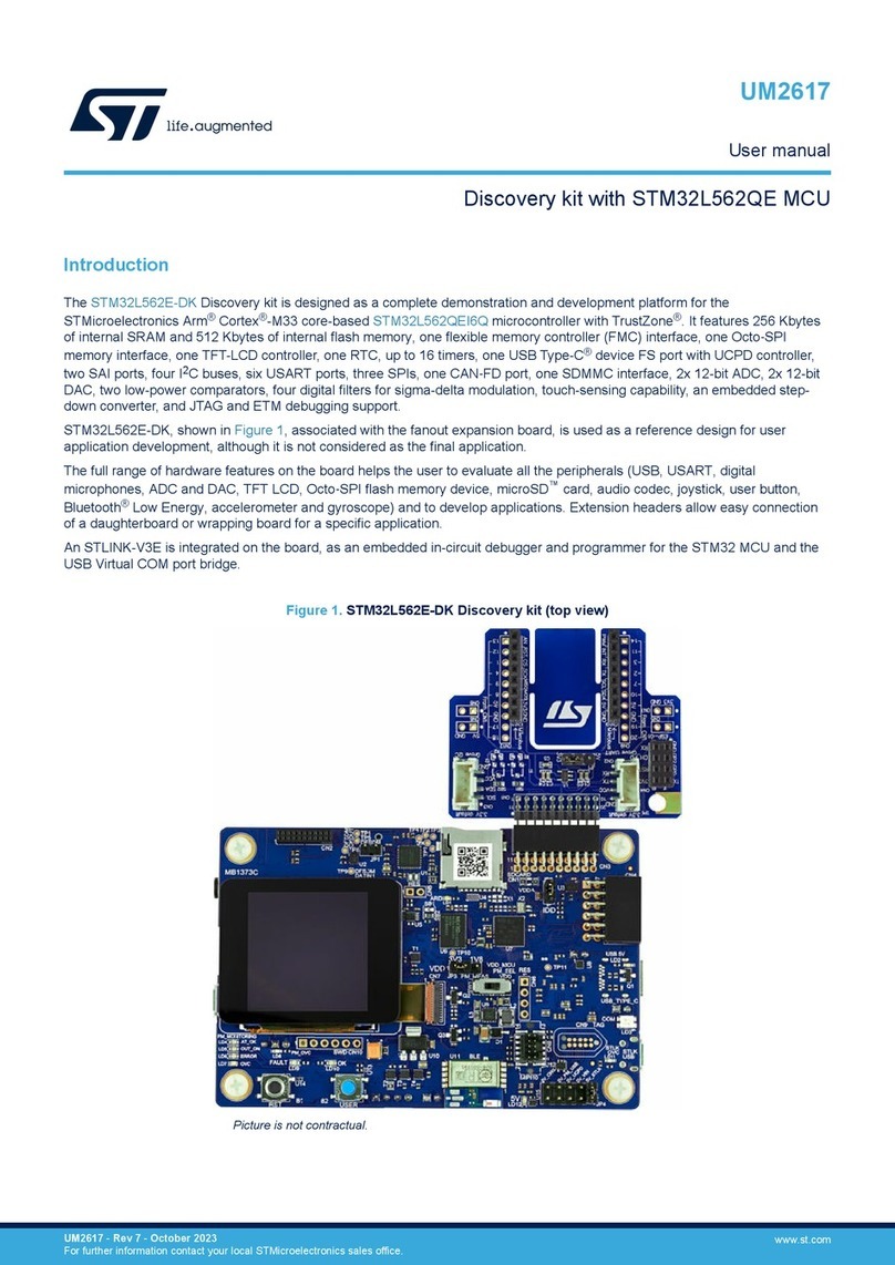
The X-STM32MP-MSP01 multisensor expansion board embeds the following devices:
•the ISM330DHCX iNEMO 3-axis accelerometer and 3-axis gyroscope
• the IIS2MDC 3-axis magnetometer
• the IIS2DLPC 3-axis accelerometer
• the MP23DB02MM digital microphone
• the LPS22HH pressure sensor
• the STTS22H temperature sensor
• the VL53L5CX Time-of-Flight sensor
• the VD6283TX ambient light sensor
• the ST25DV64KC NFC RFID tag
The X-STM32MP-MSP01 interfaces with the STM32MP157F-DK2 microprocessor via a 40-pin GPIO connector, using I²C, SPI,
and GPIO peripherals.
The X-STM32MP-MSP01 expansion board is compatible with both the STM32MP157F-DK2 and Raspberry Pi GPIO expansion
connector layout.
Figure 1. X-STM32MP-MSP01 expansion board
Getting started with the X-STM32MP-MSP01 expansion board for the
STM32MP157F-DK2 discovery kit
UM3076
User manual
UM3076 - Rev 1 - October 2022
For further information contact your local STMicroelectronics sales office. www.st.com

1Getting started
1.1 Overview
The X-STM32MP-MSP01 is powered via a standard 3.3 V supply through the STM32MP157F-DK2 GPIO
connector.
The figure below shows the component placement on the board.
Figure 2. X-STM32MP-MSP01 component placement details
The X-STM32MP-MSP01 interfaces with the main board via an I²C interface along with some GPIO pins for
interrupts. A DIL 24-pin socket is available for additional MEMS adapters and other sensors.
The I²C sensor hub features on the ISM330DHCX are also available by using solder bridges.
The expansion board mounts an LDO to generate 1.8 V for all the MEMS sensors. A level shifter between 1.8
V and 3.3 V translates all the signals between the sensors and the main board. Two LEDs and one switch are
available on the board as the user interface.
UM3076
Getting started
UM3076 - Rev 1 page 2/38

Figure 3. System block diagram
1.2 System requirements
To test the X-STM32MP-MSP01, you need:
•an X-STM32MP-MSP01 expansion board
• an STM32MP157F-DK2 discovery kit
• a laptop/desktop (with Windows 10 or above)
• a USB Type-A to micro-B USB cable (for connection as a virtual serial device, if required)
• a USB PD compliant 5 V 3 A power supply with a USB Type-C® to Type-C® cable.
1.3 Board setup
To set up the board, follow the steps below.
Step 1. Check the position of the jumper on the J4 connector.
This jumper enables the write operation for the EEPROM, if required.
UM3076
System requirements
UM3076 - Rev 1 page 3/38

Step 2. Connect the X-STM32MP-MSP01 to the STM32MP157F-DK2 from the top, as shown below.
Figure 4. X-STM32MP-MSP01 connected to STM32MP157F-DK2
Step 3. Power the STM32MP157F-DK2 using the USB Type-C® cable.
Step 4. Program the supported firmware in the microSD™ card of the STM32MP157F-DK2 board.
The X-STM32MP-MSP01 board is ready for use.
UM3076
Board setup
UM3076 - Rev 1 page 4/38

2Component description
2.1 EEPROM: M24C32-R
The M24C32-R is a 32-Kbit I²C-compatible EEPROM, organized as 4 K × 8 bits. It can operate with a supply
voltage from 1.8 V to 5.5 V
Table 1. EEPROM details
Features Description
Order code M24C32-RMN6TP
Package SO8
Operating voltage 1.8 V to 5.5 V
The EEPROM communicates with the X-STM32MP-MSP01 through I²C signals. The J4 jumper enables the write
enable feature on the device. You can perform the read and write operation by setting the jumper as detailed in
the following table.
Table 2. EEPROM jumper details
Jumper EEPROM
1-2 WRITE_ENABLE
2-3 (default) WRITE_DISABLE
Figure 5. EEPROM section
2.2 40-pin GPIO connector
The on-board devices are controlled through the main board using various peripheral pins available on a 40-pin
GPIO connector. The series resistors are used to isolate the pins of the GPIO connector.
UM3076
Component description
UM3076 - Rev 1 page 5/38

Table 3. GPIO connector pin configuration
Pin no. Name ST MPU RPi Pin no. Name ST MPU RPi
1 3V3 2 5V0
3 SDA PA12 /
I2C5_SDA
GPIO 2/
I2C1_SDA 4 5V0
5 SCL PA11 /
I2C5_SCL
GPIO3 /
I2C1_SCL 6 GND
7GPIO_IIS2MDC_INT_
DRDY PA8/ MCO1 GPIO4 /
GPCLK0 8GPIO_ISM330DHC
_INT1
PB10 /
USART3_TX
GPIO0 /
USART3
_TX
9 GND GND 10 GPIO_ISM330DHC
_INT2
PB12 /
USART3_RX
GPIO0 /
USART3
_RX
11 GPIO_LPS22HH_INT
_DRDY
PG8 /
USART3_R
TS
GPIO17 /
UART1_RTS 12 GPIO_IIS2DLPC_I
NT2
PI5 /
SAI2_SCKA
GPIO18 /
PCM CLK
13 SWITCH_1
PD7 /
SDMMC3_D
3
GPIO27 14 GND
15 GPIO_DIL24_INT1
PG15 /
SDMMC3_C
K
GPIO22 16 GPIO_FLEX_INT1
PF1 /
SDMMC3_C
MD
GPIO23 /
SD0
CMD
17 3V3 18 GPIO_ST25DV04K
_GPO
PF0 /
SDMMC3_D
0
GPIO24 /
SD0
DAT0
19 GPIO_DIL24_SPI_MO
SI
PF9/
SPI5_MOSI
GPIO10 /
SPI0_MOSI 20 GND
21 GPIO_DIL24_SPI_MI
SO
PF8 /
SPI5_MISO
GPIO9 /
SPI0_MISO 22 LED1
PF4 /
SDMMC3_D
1
GPIO25 /
SD0
DAT1
23 GPIO_DIL24_SPI_CL
K
PF7 /
SPI5_SCK
GPIO11 /
SPI0_SCK 24 GPIO_DIL24_SPI_
CS
PF6 /
SPI5_NSS
GPIO8 /
SPI0 CE0
25 GND 26 GPIO_IIS2DLPC_I
NT1 PF3 / GPIO7 GPIO7 /
SPI0 CE1
27 EEPROM_ID_SD PF15/
I2C1_SDA
GPIO0/
I2C0_SDA 28 EEPROM_ID_SC PD12 /
I2C1_SCL
GPIO1 /
I2C0 SCL
29 GPIO_STTS22H_INT PG2/ MCO2 GPIO5 /
GPCLK1 30 GND
31 GPIO_VD6283_GPIO
1
PH11 /
TIM5_CH2
GPIO6 /
GPCLK2 32 LED2 PD13 /
TIM4_CH2
GPIO12 /
PWM0
33 GPIO_MP23DB02_D
OUT
PC7/
TIM3_CH2
GPIO13 /
PWM1 34 GND
35 GPIO_VL53L_INT PI7 /
SAI2_FSA
GPIO19 /
PCM FS 36 GPIO_MP23DB02_
CLK
PB13 /
USART3_CT
S
GPIO16 /
UART1
CTS
37 GPIO_FLEX_INT2
PF5/
SDMMC3_D
2
GPIO26 /
SD0 DAT2 38 GPIO_VL53L_I2C_
RST
PI6 /
SAI2_SDA
GPIO20 /
PCM DIN
39 GND 40 GPIO_VL53L_LPn PF11 /
SAI2_SDB
GPIO21 /
PCM
DOUT
UM3076
40-pin GPIO connector
UM3076 - Rev 1 page 6/38

Figure 6. GPIO connector circuit
2.3 Level translator: ST2378E
The ST2378E device is an 8-bit, dual supply, bidirectional level translator with ±15 kV ESD protection on I/Os at
VCC side. It is designed to interface data transfer between low voltage ASICs/PLDs and higher voltage systems.
Externally applied voltage, VCC and VL, set logic levels at both sides with the range specified as 1.71 V ≤ VL≤ 5.5
V and VL≤ VCC≤ 5.5 V. For proper operation, VCC should be set higher than VL.
Using a transmission-gate-based design, this device allows bidirectional asynchronous data transfer. This means
that each channel is allowed to have either VCC to VL or VL to VCC data transfer direction independently; no
direction pin is required.
The ST2378E device operates at a guaranteed data rate of 13 Mbps over the entire specified operating voltage
range. The OE pin allows the disable mode operation whereby the current consumption is reduced to less than 1
μA.
Table 4. ST2378E details
Features Description
Order code ST2378ETTR
Package 20-TSSOP
Operating voltage 1.71 V to 5.5 V
As all the on-board sensors operate at 1.8 V, the voltage is shifted before communicating with the 40-pin GPIO
connector.
UM3076
Level translator: ST2378E
UM3076 - Rev 1 page 7/38

Figure 7. ST2378ETTR circuit
2.4 Accelerometer and gyroscope: ISM330DHCX
The ISM330DHCX is a system-in-package featuring a high-performance 3-axis digital accelerometer and 3-axis
digital gyroscope tailored for Industry 4.0 applications. The sensing elements of the accelerometer and of the
gyroscope are implemented on the same silicon die, thus guaranteeing superior stability and robustness.
The ISM330DHCX has a full-scale acceleration range of ±2/±4/±8/±16 g and a wide angular rate range of
±125/±250/±500/±1000/±2000/±4000 dps that enable its usage in a broad range of applications.
An unmatched set of embedded features (machine learning core, programmable FSM, FIFO, sensor hub, event
decoding, and interrupts) enable the implementation of smart and complex sensor nodes, which deliver a high
performance at very low power.
Table 5. ISM330DHCX details
Features Description
Order code ISM330DHCXTR
Package 14-LGA
Operating voltage 1.71 V to 3.6 V
All the design aspects and the calibration of the ISM330DHCX have been optimized to reach superior accuracy,
stability, extremely low noise, and full data synchronization.
The ISM330DHCX has an I²C sensor hub, which allows it to behave as the I²C master for other slave devices
connected via an I²C auxiliary bus. Various configurations are possible for different I²C bus connections with or
without the ISM330DHCX sensor hub.
UM3076
Accelerometer and gyroscope: ISM330DHCX
UM3076 - Rev 1 page 8/38

Figure 8. ISM330DHCXTR circuit
2.5 Linear accelerometer: IIS2DLPC
The IIS2DLPC is an ultra-low-power high-performance three-axis linear accelerometer with digital I²C/SPI output
interface, which leverages on the robust and mature manufacturing processes already used for the production
of micromachined accelerometers. The IIS2DLPC has user-selectable full scales of ±2g/±4g/±8g/±16g and is
capable of measuring accelerations with output data rates from 1.6 Hz to 1600 Hz.
The IIS2DLPC has dedicated embedded features to process motion and acceleration detection including free-fall,
wakeup, highly configurable single/double-tap recognition, activity/inactivity, stationary/motion detection, portrait/
landscape detection, and 6D/4D orientation. It features a data-ready signal, which indicates when a new set of
measured acceleration data is available, thus simplifying data synchronization in the digital system that uses the
device.
Table 6. IIS2DLPCTR details
Features Description
Order code IIS2DLPCTR
Package 12-LGA
Operating voltage 1.62 V to 3.6 V
Figure 9. IIS2DLPCTR circuit
2.6 Magnetic sensor: IIS2MDC
The IIS2MDC is a high-accuracy, ultra-low-power 3-axis digital magnetic sensor. The IIS2MDC has a magnetic
field dynamic range up to ±50 gauss.
UM3076
Linear accelerometer: IIS2DLPC
UM3076 - Rev 1 page 9/38

The IIS2MDC includes an I²C serial bus interface that supports standard, fast mode, fast mode plus, and high-
speed (100 kHz, 400 kHz, 1 MHz, and 3.4 MHz).
The device can be configured to generate an interrupt signal for magnetic field detection. It can be used as a
slave device with the ISM330DHCX device configured as a master using the solder bridge configuration.
Table 7. IIS2MDC details
Features Description
Order code IIS2MDCTR
Package 12-LGA
Operating voltage 1.71 V to 3.6 V
Figure 10. IIS2MDC circuit
2.7 Microphone: MP23DB02MM
The MP23DB02MM is an ultra-compact, low-power, omnidirectional, digital MEMS microphone built with a
capacitive sensing element and an IC interface with optional stereo configuration. The sensing element, capable
of detecting acoustic waves, is manufactured using a specialized silicon micromachining process dedicated to
produce audio sensors. It has a narrow sensitivity range of ±1 dB, high SNR, and low distortion for all operative
modes.
Table 8. MP23DB02MM details
Features Description
Order code MP23DB02MMTR
Package RHLGA 5LD
Two digital microphones are available on the board to give flexibility for different configurations. Both are mounted
from the bottom with hole on the PCB to input the audio signal. MP23DB02MM offers multiple performance
modes enabled by different clock frequency ranges (power down, low power, and normal mode).
UM3076
Microphone: MP23DB02MM
UM3076 - Rev 1 page 10/38

Figure 11. MP23DB02MM circuit
2.8 Pressure sensor: LPS22HH
The LPS22HH is an ultra-compact piezoresistive absolute pressure sensor, which functions as a digital output
barometer. The device comprises a sensing element and an IC interface, which communicates through I²C,
MIPI I3CSM, or SPI from the sensing element to the application. It can be used as a slave device with the
ISM330DHCX device configured as a master using the solder bridge configuration.
Table 9. LPS22HH details
Features Description
Order code LPS22HHTR
Package 10-HLGA
Operating voltage 1.7 V to 3.6 V
Figure 12. LPS22HH circuit
2.9 Temperature sensor: STTS22H
The STTS22H is an ultra-low-power, high accuracy, digital temperature sensor offering high performance over
the entire operating temperature range. The STTS22H is a band gap temperature sensor coupled with an A/D
converter, signal processing logic, and an I²C/SMBus 3.0 interface all in a single ASIC.
The STTS22H is factory-calibrated and requires no additional calibration efforts on the customer side.
The STTS22H units are 100% tested on a production setup that is NIST traceable and verified with equipment
that is calibrated in accordance with the IATF 16949:2016 standard.
By connecting the Addr pin to either GND or VDD, two different addresses can be specified. An interrupt pin is
also available to signal the application whenever the user-selectable high and low threshold have been exceeded.
UM3076
Pressure sensor: LPS22HH
UM3076 - Rev 1 page 11/38

Table 10. STTS22HTR details
Features Description
Order code STTS22HTR
Package 6-UDFN
Operating voltage 1.5 V to 3.6 V
Figure 13. STTS22HTR circuit
2.10 Time-of-Flight sensor: VL53L5CX
The VL53L5CX is a state of the art, Time-of-Flight (ToF), multizone ranging sensor, housed in a miniature
reflowable package. It integrates a SPAD array, physical infrared filters, and diffractive optical elements (DOE) to
achieve the best ranging performance in various ambient lighting conditions with a range of cover glass materials.
This sensor uses the direct ToF technology to allow absolute distance measurement whatever the target color and
reflectance. It provides accurate ranging up to 400 cm and can work at fast speeds (60 Hz).
Insert the following information of the ToF sensor:
The VL53L5CX characteristics are:
• laser wavelength: 940 nm
• invisible laser radiation
• maximum laser power emitted: 130 mW
• pulse duration: 2 ns with intervals of 28/32 ns
Table 11. VL53L5CX details
Features Description
Order code VL53L5CXV0GC/1
Package Optical LGA16
Operating voltage 1.8 V to 3.3 V
UM3076
Time-of-Flight sensor: VL53L5CX
UM3076 - Rev 1 page 12/38

Figure 14. VL53L5CX circuit
2.10.1 Laser safety considerations
The VL53L5CX contains a laser emitter and the corresponding drive circuitry.
The laser output is designed to remain within Class 1 laser safety limits under all reasonable foreseeable
conditions, including single faults, in compliance with the IEC 60825-1:2014 (third edition).
The laser output remains within Class 1 limits as long as you use the STMicroelectronics recommended device
settings and respect the operating conditions specified in the data sheet.
The laser output power must not be increased and no optics should be used with the intention of focusing the
laser beam.
Figure 15. Class 1 laser product label
2.11 Ambient light sensor: VD6283TX
The VD6283TX is a color sensor with advanced light flicker extraction. The light measurement is fast and
accurate, thanks to an individual ADC and a readout for each color channel. The VD6283TX uses hybrid color
filters with precise responses, allowing accurate computation of the correlated color temperature (CCT) and lux
information. Additionally, the VD6283TX has the ability to extract different light flicker waveforms from 100 Hz and
2 kHz, including LED square signals, that can run flicker operations simultaneously with ALS operations.
Table 12. VD6283TX details
Features Description
Order code VD6283TX
Package Optical BGA
Operating voltage 1.8 V
UM3076
Ambient light sensor: VD6283TX
UM3076 - Rev 1 page 13/38

Figure 16. VD6283TX circuit
2.12 NFC tag: ST25DV64KC
The ST25DV64KC is NFC RFID tag that includes 64‑Kbit of electrically erasable programmable memory
(EEPROM) with two interfaces. The first one is an I²C serial link and can be operated from a DC power supply.
The second one is an RF link activated when it acts as a contactless memory powered by the received carrier
electromagnetic wave. In the I²C mode, the ST25DV64KC user memories contain 8192 bytes, which could be
split into four flexible and protectable areas.
A GPO pin for interruption pin configurable on multiple RF events (field change, memory write, activity, Fast
Transfer end, user set/reset/pulse) is available.
Table 13. ST25DV64KC details
Features Description
Order code ST25DV64KC-IE6S3
Package 8-SOIC
Operating voltage 1.8 V to 5.5 V
Figure 17. ST25DV64KC circuit
As the ST25DV64KC is a tag, it does not generate any power. It is activated with the power of a reader.
It is tuned to work at 13.56 Mhz. There is no channel.
The reader emits a 13.56 radio frequency.
The ST25DV64KC is powered by this electromagnetic field and modulates it to exchange data.
UM3076
NFC tag: ST25DV64KC
UM3076 - Rev 1 page 14/38

2.13 LDO: LDK130
The LDK130 low drop voltage regulator provides 300 mA of maximum current from an input supply voltage in the
range of 1.9 V to 5.5 V, with a typical dropout voltage of 100 mV. It is stabilized with a ceramic capacitor on the
output. The very low drop voltage, low quiescent current and low-noise features make it suitable for low-power
battery-powered applications. An enable logic control function puts the LDK130 in shutdown mode, allowing a
total current consumption lower than 1 μA. The device also includes the short-circuit constant current limiting and
thermal protection.
On-board sensors operate on a 1.8 V power supply. The LDK130 is used to generate 1.8 V power supply for the
various sections.
Table 14. LDK130 details
Features Description
Order code LDK130M-R
Package SOT23-5
Operating voltage 1.9 V to 5.5 V
Figure 18. LDK130 circuit
2.14 LEDs and switches
On-board LEDs are available for visual indication. A push button switch is used for the user inputs.
Note: You can configure different hardware settings of the X-STM32MP-MSP01 board through several solder bridges,
which can be left open (not mounted) or closed (mounted).
UM3076
LDO: LDK130
UM3076 - Rev 1 page 15/38

Figure 19. LED and switch circuit
2.15 Other connectors: DIL 24-pin socket, flexible cable, I²C groove connector
Several connectors are available on the board to connect external boards:
•a DIL 24-pin socket (J10) for additional adapter boards
• a flexible cable connector (J12) for various probe kits
• an I²C groove connector (J11) for external modules (twigs) using I²C connectivity
Figure 20. DIL-24, flexible cable, I²C groove connector circuit
UM3076
Other connectors: DIL 24-pin socket, flexible cable, I²C groove connector
UM3076 - Rev 1 page 16/38

3Schematic diagrams
Figure 21. X-STM32MP-MSP01 circuit schematic (1 of 11)
ISM330DHCX_IIS2DLPC1
Page5_Acc & Gyro_sensor
I2C1_SDA
I2C1_SCL
ISM330DHC_INT2
IIS2DLPC_INT1
IIS2DLPC_INT2
ISM330DHC_INT1
ISM330DHC_SDX
ISM330DHC_SCX
IIS2MDC_INT_DRDY
LPS22HH_INT_DRDY
M24C32-RMN6TP1
Page2_EEPROM
EEPROM_ID_SD
EEPROM_ID_SC
ST2378E1
Page4_Level_Shifter
ISM330DHC_INT2 GPIO_ISM330DHC_INT2
GPIO_STTS22H_INTSTTS22H_INT
GPIO_IIS2DLPC_INT1
GPIO_IIS2DLPC_INT2
IIS2DLPC_INT1
IIS2DLPC_INT2
GPIO_VL53L_INTVL53L_INT
VL53L_LPn
VD6283_GPIO1
I2C1_SCL
GPIO_SCL
I2C1_SDA
GPIO_SDA
VL53L_I2C_RST GPIO_VL53L_I2C_RST
ST25DV04K_GPO
GPIO_ST25DV04K_GPO
GPIO_VL53L_LPn
ISM330DHC_INT1
GPIO_MP23DB02_DOUT
GPIO_VD6283_GPIO1
GPIO_DIL24_SPI_CS
GPIO_FLEX_INT2
GPIO_FLEX_INT1
GPIO_MP23DB02_CLK
GPIO_IIS2MDC_INT_DRDY
GPIO_DIL24_SPI_CLK
GPIO_DIL24_SPI_MISO
DIL24_SPI_CS
GPIO_ISM330DHC_INT1
FLEX_INT2
MP23DB02_DOUT
DIL24_SPI_CLK
FLEX_INT1
DIL24_INT1
MP23DB02_CLK
IIS2MDC_INT_DRDY
DIL24_SPI_MOSI
DIL24_SPI_MISO
GPIO_DIL24_INT1
GPIO_DIL24_SPI_MOSI
LPS22HH_INT_DRDY GPIO_LPS22HH_INT_DRDY
IIS2MDC_MP23DB02MM1
Page6_Magnetometer_Audio_Sensor
I2C1_SCL
I2C1_SDA
MP23DB02_DOUT
ISM330DHC_SDX
ISM330DHC_SCX
MP23DB02_CLK
IIS2MDC_INT_DRDY
DIL24_SPI_CS
DIL24_SPI_MISO
LDO_LEDs & Switches1
Page_11_LDO_LEDs & Switches
LED1
SWITCH_1
LED2
LPS22HH_STTS22H1
Page7_Pressure_Temp_sensor
I2C1_SCL
I2C1_SDA
STTS22H_INT
ISM330DHC_SCX
ISM330DHC_SDX
LPS22HH_INT_DRDY
GPIO_Expansion_Connector1
Page3_Connector
LED2
GPIO_SCL
LED1
EEPROM_ID_SC
GPIO_IIS2DLPC_INT1
EEPROM_ID_SD
GPIO_IIS2DLPC_INT2
GPIO_VL53L_LPn
SWITCH_1
GPIO_SDA
GPIO_STTS22H_INT
GPIO_ISM330DHC_INT2
GPIO_VL53L_INT
GPIO_VL53L_I2C_RST
GPIO_ST25DV04K_GPO
GPIO_MP23DB02_DOUT
GPIO_FLEX_INT1
GPIO_DIL24_SPI_CS
GPIO_FLEX_INT2
GPIO_VD6283_GPIO1
GPIO_MP23DB02_CLK
GPIO_DIL24_SPI_CLK
GPIO_DIL24_SPI_MISO
GPIO_ISM330DHC_INT1
GPIO_IIS2MDC_INT_DRDY
GPIO_DIL24_INT1
GPIO_DIL24_SPI_MOSI
GPIO_LPS22HH_INT_DRDY
VL53L3CX_VD1
Page8_ToF_Ambient_Sensor
I2C1_SCL
I2C1_SDA
VL53L_INT
VL53L_I2C_RST
VD6283_GPIO1
VL53L_LPn
ST25DV1
Page9_NFC
I2C1_SCL
I2C1_SDA
ST25DV04K_GPO
DIL24_I2C_Flex1
Page_10_Connectors_DIL_I2C_Flex
I2C1_SCL
I2C1_SDA
GPIO_SDA
DIL24_SPI_CS
FLEX_INT2
DIL24_SPI_CLK
FLEX_INT1
DIL24_INT1
ISM330DHC_SDX
ISM330DHC_SCX
DIL24_SPI_MOSI
DIL24_SPI_MISO
GPIO_SCL
GPIO_SDA
GPIO_SCL
GPIO_SCL
GPIO_SDA
IIS2MDC_INT_DRDYIIS2MDC_INT_DRDY
LPS22HH_INT_DRDYLPS22HH_INT_DRDY DIL24_SPI_CS
DIL24_SPI_MISO
DIL24_SPI_MISO
DIL24_SPI_CS
UM3076 - Rev 1 page 17/38
UM3076
Schematic diagrams

Figure 22. X-STM32MP-MSP01 circuit schematic (2 of 11)
Camera slot
17mm
2mm
WRITE_ENABLE
Jumper
1- 2
2- 3 ( DEFAULT)
WRITE_DISABLE
EEPROM (WC)
EEPROM_ID_SD
EEPROM_ID_SC
3V3
3V3
R5
22K
NM
R6
22K
NM
R2
1K
J8
Mouting hole_3.2mm drill
1
J5
Mouting hole_3.2mm drill 1
R1
1K
FIDUCIAL3
Fiducial
R7
22K
NM
R3
3.9K
C1
100nF
R4
3.9K
J6
Mouting hole_3.2mm drill
1
SB3
Open
NM
FIDUCIAL2
Fiducial
SB2
Open
NM
J4
3-pin Male Header
1
2
3
SB1
Open
NM
FIDUCIAL1
Fiducial
J7
Mouting hole_3.2mm drill 1
U1
M24C32-RMN6TP
E0
1
E1
2
E2
3
SDA 5
SCL 6
WC 7
VCC 8
VSS
4
UM3076 - Rev 1 page 18/38
UM3076
Schematic diagrams

Figure 23. X-STM32MP-MSP01 circuit schematic (3 of 11)
GPIO_IIS2MDC_INT_DRDY
SWITCH_1
GPIO_LPS22HH_INT_DRDY
GPIO_ISM330DHC_INT1
GPIO_STTS22H_INT
GPIO_ISM330DHC_INT2
GPIO_VL53L_INT
GPIO_VD6283_GPIO1
GPIO_ST25DV04K_GPO
GPIO_FLEX_INT2
GPIO_IIS2DLPC_INT1
GPIO_DIL24_SPI_MISO
GPIO_FLEX_INT1
GPIO_DIL24_INT1
GPIO_SDA
GPIO_SCL
GPIO_DIL24_SPI_MOSI
GPIO_DIL24_SPI_CLK
LED1
LED2
GPIO_DIL24_SPI_CS
GPIO_VL53L_LPn
EEPROM_ID_SCEEPROM_ID_SD
GPIO_MP23DB02_CLK
GPIO_IIS2DLPC_INT2
GPIO_VL53L_I2C_RSTGPIO_MP23DB02_DOUT
3V3 5V0 5V0
R32 0
R17 0
R10 0
C3
100nF
R15 0
R21 0
C2
100nF
C4
100nF
R31 0
R35 0
R29 0
R28 0
R16 0
R13 0
R12 0
R18 0
R22 0
R23 0
R27 0
R9 0
R34 0
R26 0
R8 0
R19 0
R25 0
R33 0
R24 0
R30 0
CN2
Header 20X2_female
33
1 2
3 4
5 6
7 8
9 10
11 12
13 14
15 16
17 18
19 20
21 22
23 24
25 26
27 28
29 30
31 32
34
35 36
37 38
39 40
R11 0
R20 0
R14 0
C5
100nF
SDA
SCL
#7
#11
#13
#15
#22
#23
ID_SD ID_SC
#33
SDA
#32
SCL
#38
#7
#40
#11
#22
#13
#15
ID_SC
#19
#21
#23
ID_SD
#33
#29
#29
#31
#31 #32
#8
#10
#8
#10
#40
#38
#35
#12
CE1
CE2
CE1
CE2
#12
#35
#16
#18
#16
#18
#19
#21
#37
#37
CE0
CE0
UM3076 - Rev 1 page 19/38
UM3076
Schematic diagrams

Figure 24. X-STM32MP-MSP01 circuit schematic (4 of 11)
LPS22HH_INT_DRDY
MP23DB02_DOUT
VL53L_INT
GPIO_MP23DB02_CLK
ST25DV04K_GPO
FLEX_INT1
FLEX_INT2
DIL24_SPI_MISO
STTS22H_INT
GPIO_DIL24_SPI_MOSI
GPIO_DIL24_SPI_CLK
GPIO_DIL24_SPI_CS
VD6283_GPIO1
IIS2DLPC_INT1
IIS2DLPC_INT2
DIL24_INT1
IIS2MDC_INT_DRDY
GPIO_DIL24_SPI_MISO
GPIO_DIL24_INT1
GPIO_IIS2MDC_INT_DRDY
DIL24_SPI_MOSI
DIL24_SPI_CLK
DIL24_SPI_CS
I2C1_SCL
I2C1_SDA
GPIO_SCL
GPIO_SDA
GPIO_IIS2DLPC_INT1
GPIO_IIS2DLPC_INT2
GPIO_LPS22HH_INT_DRDY
GPIO_MP23DB02_DOUT
GPIO_STTS22H_INT
MP23DB02_CLK
GPIO_FLEX_INT2
GPIO_FLEX_INT1
GPIO_VL53L_INT
GPIO_VD6283_GPIO1
GPIO_ST25DV04K_GPO
GPIO_VL53L_LPnVL53L_LPn
GPIO_VL53L_I2C_RSTVL53L_I2C_RST
GPIO_ISM330DHC_INT1
GPIO_ISM330DHC_INT2
ISM330DHC_INT1
ISM330DHC_INT2
1V8
1V8
1V8
1V8
1V8
1V8
3V3
3V3
3V3
3V3
1V8
3V3
1V8
3V3
1V8
1V8 3V3
C10 100nF
R39
1.5K
R36
1.5K C8 100nF
C11 100nF
U2
ST2378ETTR
VL
1
I/O_VL1
2
I/O_VCC2 3
I/O_VL3
4
I/O_VCC4 5
GND
10
I/O_VL4
16 I/O_VCC3 17
I/O_VL2
18 I/O_VCC1 19
VCC 20
EN (OE) 11
I/O_VL5
6
I/O_VCC6 7
I/O_VL7
8
I/O_VCC8 9
I/O_VCC5 15
I/O_VL6
14
I/O_VCC7 13
I/O_VL8
12
C7 100nF
R37
1.5K
C9 100nF
R41 4.7K
U3
ST2378ETTR
VL
1
I/O_VL1
2
I/O_VCC2 3
I/O_VL3
4
I/O_VCC4 5
GND
10
I/O_VL4
16 I/O_VCC3 17
I/O_VL2
18 I/O_VCC1 19
VCC 20
EN (OE) 11
I/O_VL5
6
I/O_VCC6 7
I/O_VL7
8
I/O_VCC8 9
I/O_VCC5 15
I/O_VL6
14
I/O_VCC7 13
I/O_VL8
12
U4
ST2378ETTR
VL
1
I/O_VL1
2
I/O_VCC2 3
I/O_VL3
4
I/O_VCC4 5
GND
10
I/O_VL4
16 I/O_VCC3 17
I/O_VL2
18 I/O_VCC1 19
VCC 20
EN (OE) 11
I/O_VL5
6
I/O_VCC6 7
I/O_VL7
8
I/O_VCC8 9
I/O_VCC5 15
I/O_VL6
14
I/O_VCC7 13
I/O_VL8
12
R40 4.7K
C6 100nF
R38
1.5K
UM3076 - Rev 1 page 20/38
UM3076
Schematic diagrams
Table of contents
Other ST Computer Hardware manuals

ST
ST X-CUBE-SBSFU User manual

ST
ST X-NUCLEO-IDW04A1 User manual

ST
ST CLT01-38SQ7 User manual

ST
ST X-NUCLEO-53L5A1 User manual

ST
ST STEVAL-SCR002V1 User manual

ST
ST X-NUCLEO-LED61A1 User manual

ST
ST X-NUCLEO-6283A1 User manual

ST
ST STEVAL-OET005 User manual

ST
ST ST92163 User manual

ST
ST X-NUCLEO-GNSS2A1 User manual

ST
ST METERS AND MORE UM2241 User manual

ST
ST STM32Cube Quick setup guide

ST
ST X-NUCLEO-IDS01A4 User manual

ST
ST STM32F3 Series Owner's manual

ST
ST STEVAL-MKI015V1 Quick start guide

ST
ST X-LINUX-NFC5 User manual

ST
ST X-NUCLEO-OUT12A1 User manual

ST
ST STEVAL-IFP047V1 User manual
ST
ST HTSSOP38 User manual

ST
ST STSW-ST25DV002 User manual