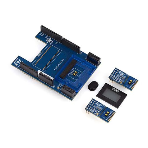
ST UM2960 User manual
Other ST Computer Hardware manuals

ST
ST Nomadik NHK-15 User manual
ST
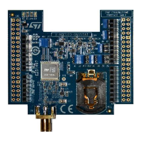
ST X-NUCLEO-GNSS1A1 User manual

ST
ST X-NUCLEO-IHM12A1 User manual
ST
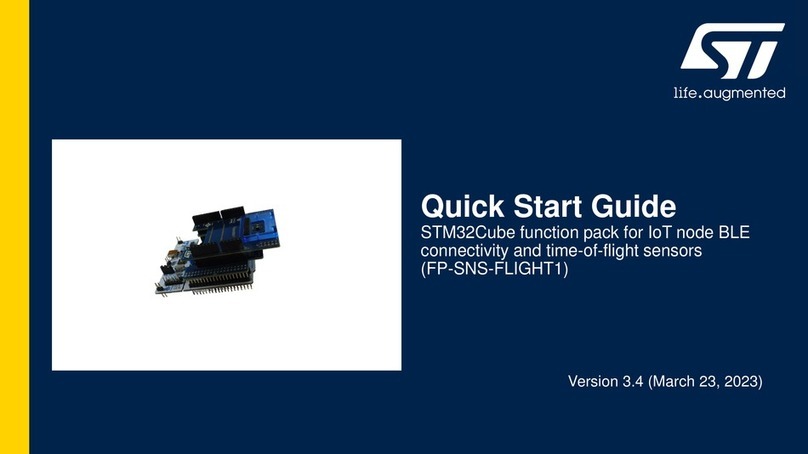
ST FP-SNS-FLIGHT1 User manual
ST
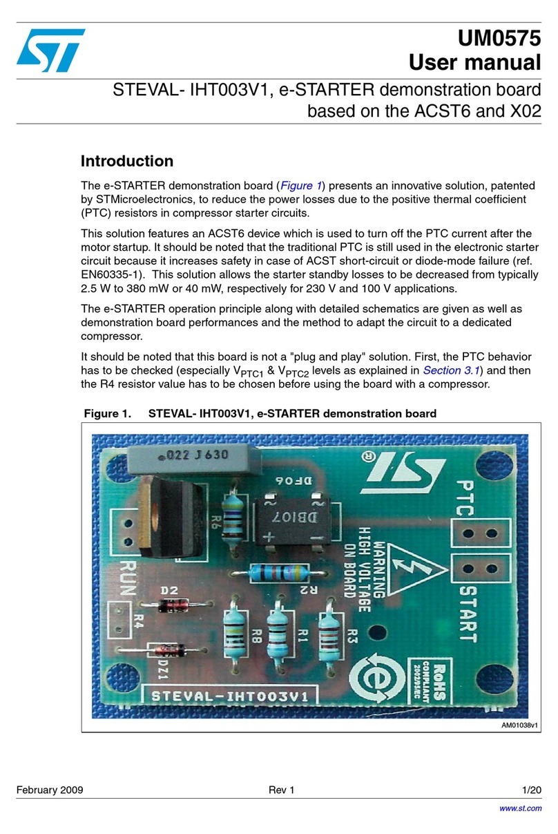
ST UM0575 User manual
ST
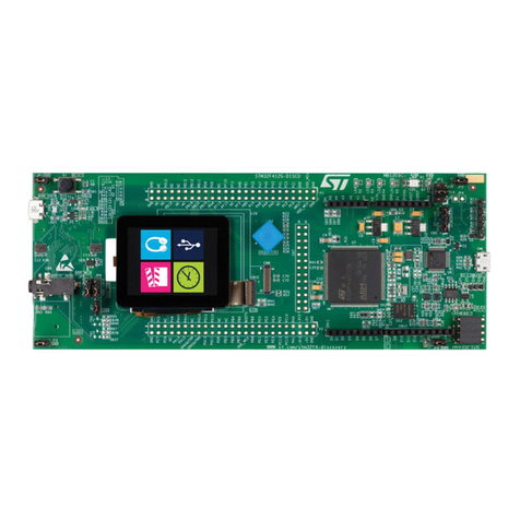
ST 32F412GDISCOVERY User manual

ST
ST X-NUCLEO-NFC01A1 User manual
ST
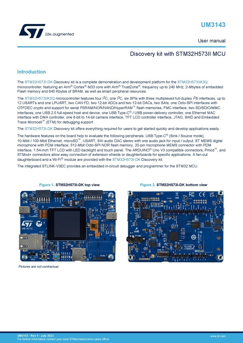
ST STM32H573I-DK User manual
ST
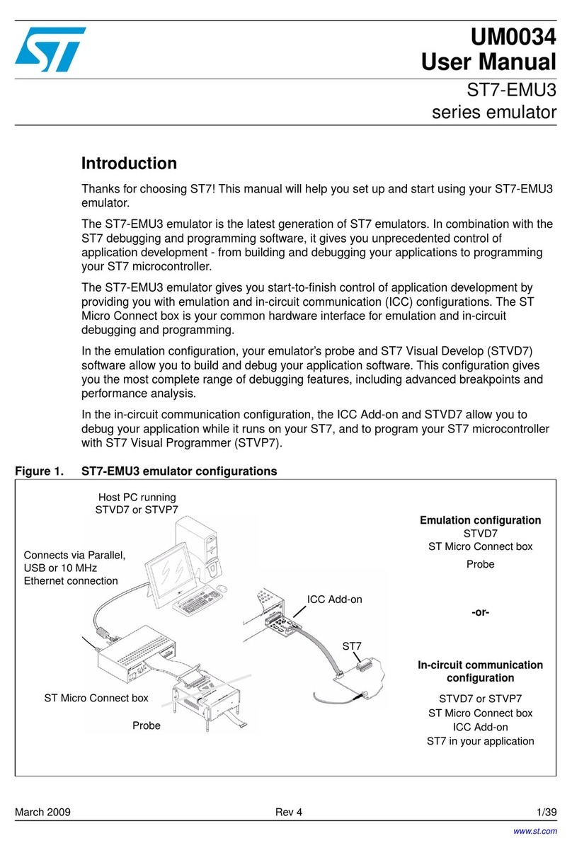
ST ST7-EMU3 Series User manual

ST
ST X-NUCLEO-GNSS2A1 User manual
ST
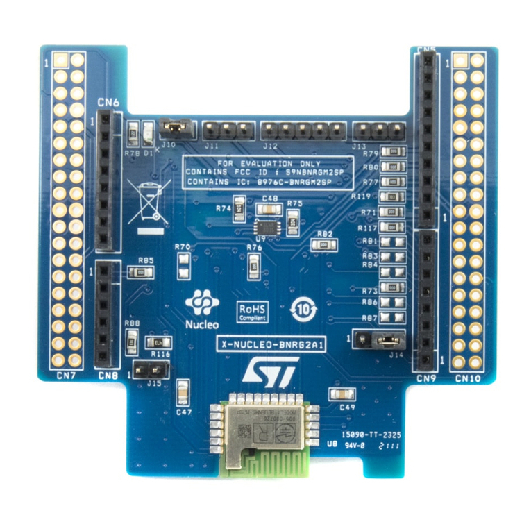
ST X-NUCLEO-BNRG2A1 User manual
ST
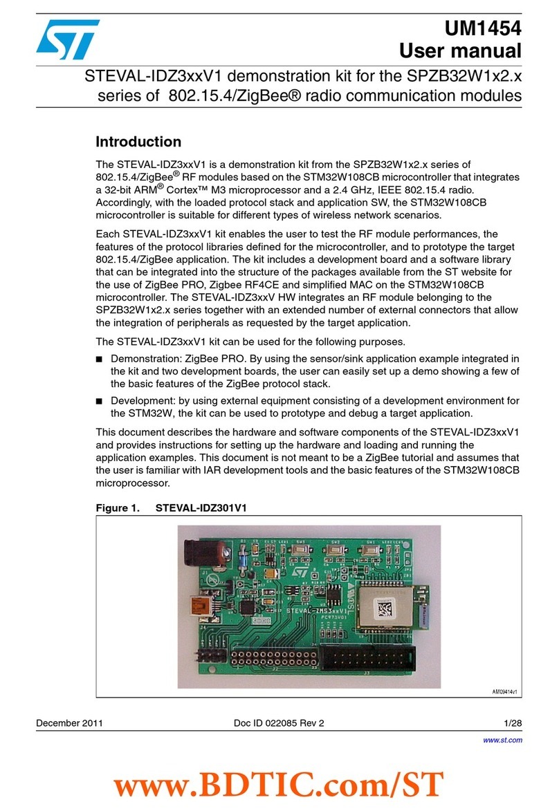
ST STEVAL-IDZ3V1 Series User manual
ST
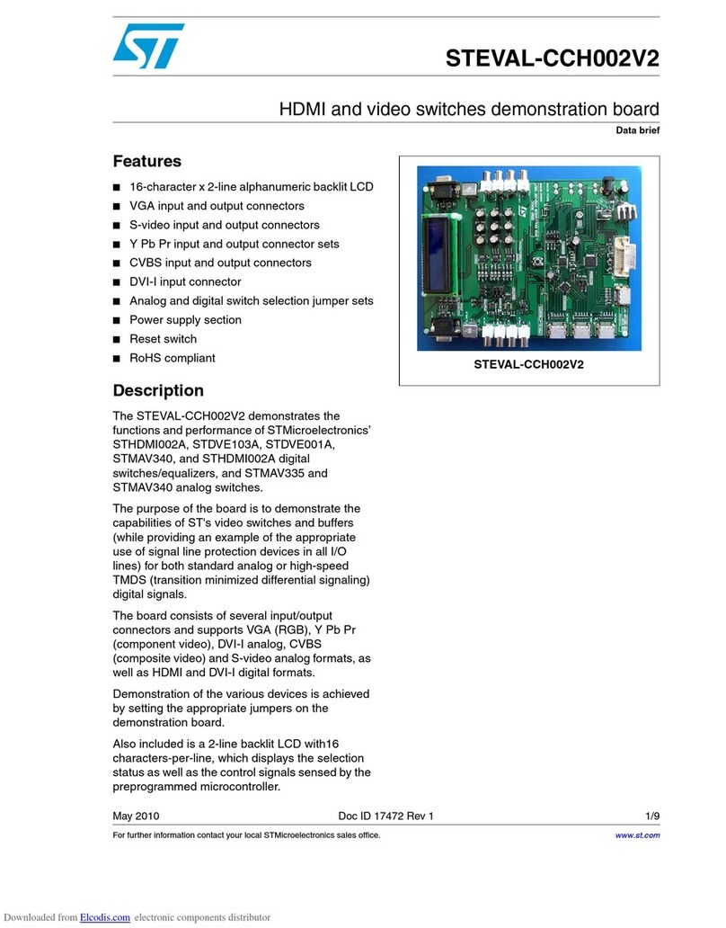
ST STEVAL-CCH002V2 User manual
ST
ST STM32 Nucleo User manual
ST
ST STM32Cube User manual
ST
ST X-NUCLEO-IHM11M1 User manual
ST
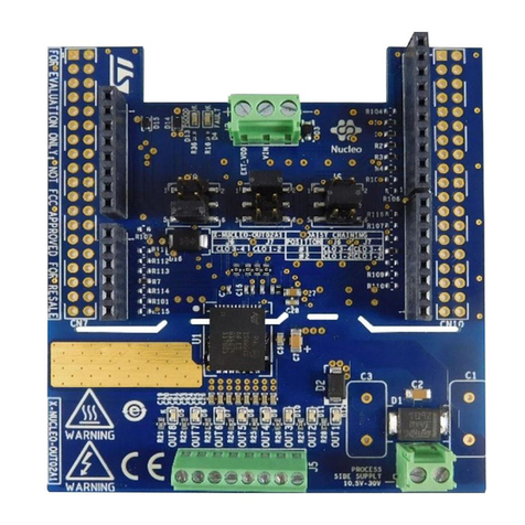
ST X-NUCLEO-OUT05A1 User manual
ST
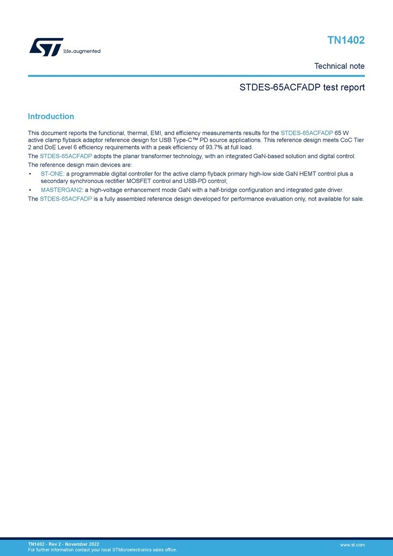
ST 32L152CDISCOVERY User manual
ST
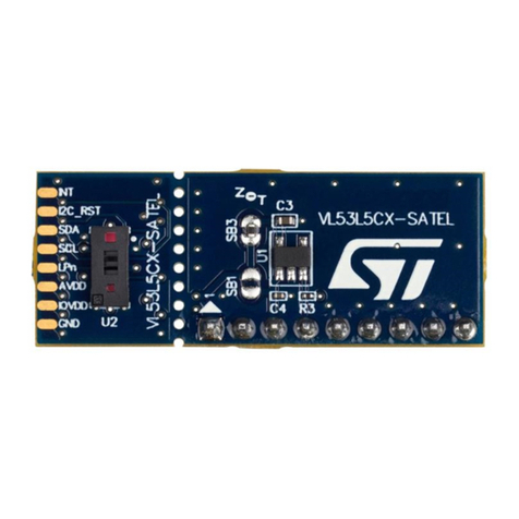
ST STDES-65ACFADP Specification sheet
ST
ST AN5717 Installation and operating instructions
Popular Computer Hardware manuals by other brands

EMC2
EMC2 VNX Series Hardware Information Guide

Panasonic
Panasonic DV0PM20105 Operation manual

Mitsubishi Electric
Mitsubishi Electric Q81BD-J61BT11 user manual

Gigabyte
Gigabyte B660M DS3H AX DDR4 user manual

Raidon
Raidon iT2300 Quick installation guide

National Instruments
National Instruments PXI-8186 user manual

Intel
Intel AXXRMFBU4 Quick installation user's guide

Kontron
Kontron DIMM-PC/MD product manual

STEINWAY LYNGDORF
STEINWAY LYNGDORF SP-1 installation manual

Advantech
Advantech ASMB-935 Series user manual

Jupiter
Jupiter RAM PACK instructions

Measurement Computing
Measurement Computing CIO-EXP-RTD16 user manual
