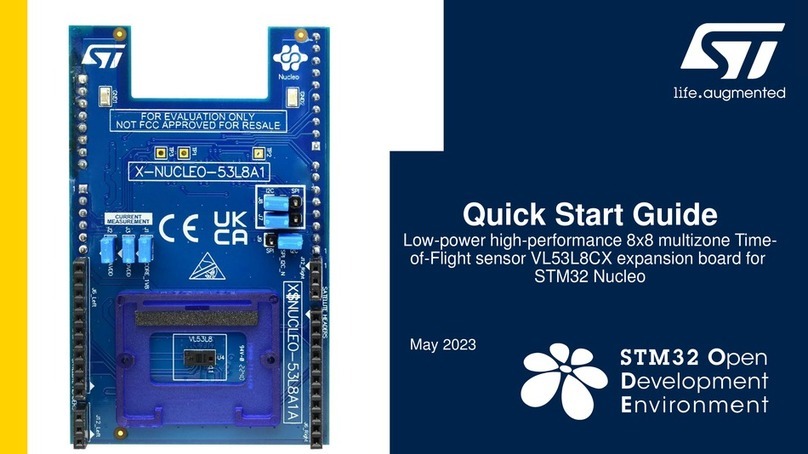
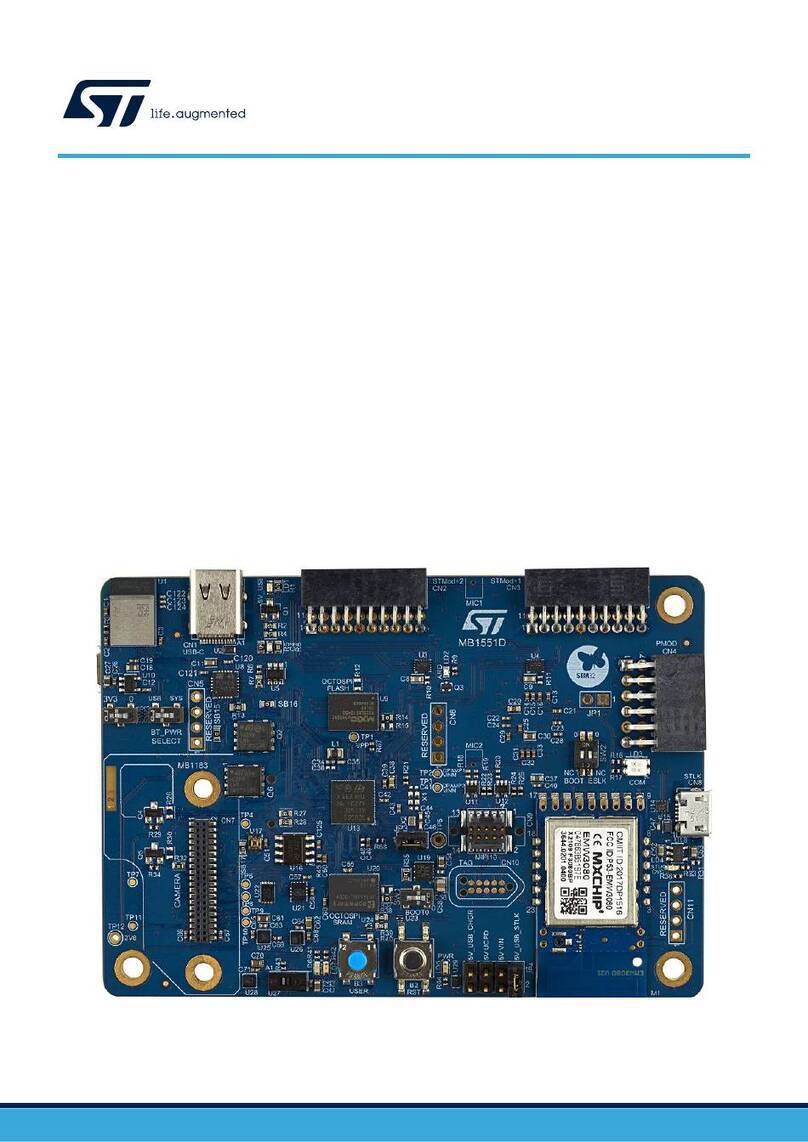
ST X-NUCLEO-IHM08M1 User manual

Chipsmall Limited consists of a professional team with an average of over 10 year of expertise in the distribution
of electronic components. Based in Hongkong, we have already established firm and mutual-benefit business
relationships with customers from,Europe,America and south Asia,supplying obsolete and hard-to-find components
to meet their specific needs.
With the principle of “Quality Parts,Customers Priority,Honest Operation,and Considerate Service”,our business
mainly focus on the distribution of electronic components. Line cards we deal with include
Microchip,ALPS,ROHM,Xilinx,Pulse,ON,Everlight and Freescale. Main products comprise
IC,Modules,Potentiometer,IC Socket,Relay,Connector.Our parts cover such applications as commercial,industrial,
and automotives areas.
We are looking forward to setting up business relationship with you and hope to provide you with the best service
and solution. Let us make a better world for our industry!
Contact us
Tel: +86-755-8981 8866 Fax: +86-755-8427 6832
Email & Skype: [email protected]om Web: www.chipsmall.com
Address: A1208, Overseas Decoration Building, #122 Zhenhua RD., Futian, Shenzhen, China

May 2016
DocID028716 Rev 2
1/29
www.st.com
UM1996
User manual
Getting started with X-NUCLEO-IHM08M1 low-voltage BLDC motor
driver expansion board based on STL220N6F7 for STM32 Nucleo
Introduction
The X-NUCLEO-IHM08M1 is a three-phase brushless DC motor driver expansion board based on
STripFET™ F7 Power MOSFET STL220N6F7 for STM32 Nucleo. It provides an affordable and easy-to-
use solution for driving a three-phase brushless DC motor in your STM32 Nucleo project. The X-
NUCLEO-IHM08M1 is compatible with the ST morpho connector and supports further stacking of
additional boards on a single STM32 Nucleo board. You can also mount the Arduino™ UNO R3
connector.
The X-NUCLEO-IHM08M1 is fully configurable and ready to support different closed loop control
scenarios based on sensorless or sensor mode control, and it is compatible with three-shunt or single-
shunt current sense measuring. The L6398 IC driver used on this STM32 Nucleo expansion board is a
single-chip half bridge gate driver for the N-channel power MOSFET. This combination of the L6398
gate driver and the STL220N6F7 Power MOSFET forms a high current power platform for BLDC
motors, while the digital section supported by the STM32 Nucleo board allows for a 6-step or FOC
control algorithm solution, which you can select via the firmware. This document describes how to
configure the X-NUCLEO-IHM08M1 expansion board to operate with STM32 Nucleo board.
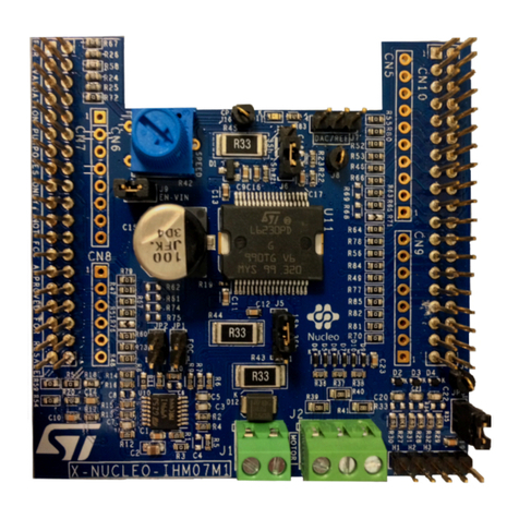
Figure 1: X-NUCLEO-IHM08M1 low-voltage BLDC motor driver expansion board based on STL220N6F7 for
STM32 Nucleo

Contents
UM1996
2/29
DocID028716 Rev 2
Contents
1System overview ............................................................................. 5
1.1 Main characteristics ..........................................................................5
1.2 Target applications............................................................................5
2Getting started................................................................................. 6
2.1 System architecture ..........................................................................6
2.2 Building the system ...........................................................................6
2.2.1 Hardware settings............................................................................... 8
3Board schematics.......................................................................... 12
4Circuit description......................................................................... 15
4.1 Power section.................................................................................. 15
4.1.1 L6398 gate driver and STL220N6F7 STripFET™ F7 Power
MOSFET .......................................................................................................... 15
4.1.2 Overcurrent detection (OCP) and current sensing measurement.... 16
4.2 Analog section................................................................................. 17
4.2.1 Hall/Encoder motor speed sensor .................................................... 17
4.3 BEMF detection circuit .................................................................... 18
5Bill of materials.............................................................................. 19
6X-NUCLEO-IHM08M1 STM32 PMSM FOC SDK parameters ........ 27
7Revision history ............................................................................ 28

UM1996
List of tables
DocID028716 Rev 2
3/29
List of tables
Table 1: Jumper settings ............................................................................................................................8
Table 2: Screw terminals ............................................................................................................................8
Table 3: ST morpho connector –CN7 ........................................................................................................9
Table 4: ST morpho connector –CN10 ....................................................................................................10
Table 5: BoM (1 of 2) ................................................................................................................................19
Table 6: BoM (2 of 2) ................................................................................................................................23
Table 7: Document revision history ..........................................................................................................28

List of figures
UM1996
4/29
DocID028716 Rev 2
List of figures
Figure 1: X-NUCLEO-IHM08M1 low-voltage BLDC motor driver expansion board based on
STL220N6F7 for STM32 Nucleo ................................................................................................................1
Figure 2: System functional hardware blocks .............................................................................................6
Figure 3: X-NUCLEO-IHM08M1 plugged on STM32 Nucleo board ...........................................................7
Figure 4: X-NUCLEO-IHM08M1 top layer with silk-screen.........................................................................9
Figure 5: Power section ............................................................................................................................12
Figure 6: Current sensing and B-emf circuit .............................................................................................12
Figure 7: Auxiliary power supply circuit ....................................................................................................13
Figure 8: Sensing and Hall/Encoder circuit...............................................................................................13
Figure 9: Analog conditioning and current protection circuit.....................................................................13
Figure 10: MCU pin-out assignment .........................................................................................................14
Figure 11: X-NUCLEO-IHM08M1 –power section...................................................................................16
Figure 12: X-NUCLEO-IHM08M1 –OCP circuit.......................................................................................16
Figure 13: X-NUCLEO-IHM08M1 –Current sensing circuit (1 of 3).........................................................17
Figure 14: X-NUCLEO-IHM08M1 –Current sensing circuit (2 of 3).........................................................17
Figure 15: X-NUCLEO-IHM08M1 –Current sensing circuit (3 of 3).........................................................17
Figure 16: X-NUCLEO-IHM08M1 –Hall/Encoder sensor circuit ..............................................................17
Figure 17: X-NUCLEO-IHM08M1 –BEMF detection circuit .....................................................................18
Figure 18: X-NUCLEO-IHM08M1 –VBUS and temperature sensing circuit............................................18

UM1996
System overview
DocID028716 Rev 2
5/29
1 System overview
1.1 Main characteristics
Three-phase driver board for BLDC/PMSM motors
Nominal operating voltage range from 8 V to 48 V DC
15 ARMS output current
Operating frequency selectable by firmware
Overcurrent detection and protection (30 APEAK)
Thermal measuring and overheating protection
Full compatible with ST Six Step or ST FOC control algorithm
Full support for sensorless and sensor mode
3-shunt and 1-shunt configurable jumpers for motor current sensing
Hall / Encoder motor sensor connector and circuit
Debug connector for DAC, GPIOs, etc.
Potentiometer available for speed regulation
User LED
Compatible with STM32 Nucleo boards
Equipped with ST morpho connectors
RoHS compliant
1.2 Target applications
The target applications for the X-NUCLEO-IHM08M1 include:
Low voltage PMSM motor driver
Low power fans
Power tools
Industrial drives

Getting started
UM1996
6/29
DocID028716 Rev 2
2 Getting started
2.1 System architecture
A generic motor control system can be basically schematized as the arrangement of three
main functional blocks (see System functional hardware blocks):
Control block accepts user commands to drive a motor. The X-NUCLEO-IHM08M1 is
based on the STM32 Nucleo board, which provides all the digital signals for effective
motor driving control.
Power block is based on the 3-phase inverter topology. The core of the power block
is the embedded L6398 driver, which contains all the necessary active power and
analog components to perform low voltage PMSM motor control.
Motor the X-NUCLEO-IHM08M1 is able to proper drive a low voltage BLDC/PMSM
motor.
This section describes how to set up different hardware parts before writing and executing
an application on the STM32 Nucleo board with the low-voltage BLDC motor driver
expansion board.
Figure 2: System functional hardware blocks
2.2 Building the system
The X-NUCLEO-IHM08M1 expansion board (Power block in the figure above) is a
complete hardware development platform for the STM32 Nucleo board allowing effective
evaluation of motor control solutions for single BLDC/PMSM motors. For regular board
operation, please follow the steps below:
1. Plug the expansion board on an STM32 Nucleo main board (Control block) through
the ST morpho connector; there is only one position allowed for this connection.
Ensure that the blue (B1) and black (B2) buttons on the STM32 Nucleo board are not
covered, as shown below.

UM1996
Getting started
DocID028716 Rev 2
7/29
Figure 3: X-NUCLEO-IHM08M1 plugged on STM32 Nucleo board
The interconnection between the STM32 Nucleo board and the X-NUCLEO-IHM08M1
expansion board is designed for full-compatibility with a wide range of STM32 Nucleo
boards without any solder bridge modifications, except for the removal of resistor R60 on
the NUCLEO-F401RE Nucleo board if the X-CUBE-SPN8 firmware is installed.
The stacked system is ready to operate with the connection of a BLDC/PMSM motor. For
correct use, please follow the hardware and software settings. For software details, please
refer to X-CUBE-SPN8 documentation available on www.st.com.
1. Connect the three motor wires U,V,W to the J16 connector.
2. To select the control algorithm (6-step or FOC), ensure no voltage supply is
connected.
On the STM32 NUCLEO board, set jumpers: JP1 open, JP5 (PWR) on E5V side, JP6
(IDD) closed.On the X-NUCLEO-IHM08M1 expansion board, set jumpers: J9 open,
JP3 closed.
For 6-step control (X-CUBE-SPN8 FW), set jumpers: JP1 and JP2 open, J5&J6
on the 1-Sh side. Keep capacitor C5 mounted; in case of poor motor current
regulation during startup, reduce its value.
For FOC control (STSW-STM32100 FW), set jumpers: JP1 and JP2 closed,
J5&J6 on the 3-Sh side. Remove capacitors C3, C5 and C7.
3. Connect the DC supply voltage to the J1 connector. An external power supply is
required to power up the power board and the STM32 Nucleo board. Be sure to
supply the right power for the connected motor; (e.g., max. 12V and 2A for the
BR2804 motor).

Getting started
UM1996
8/29
DocID028716 Rev 2
When using a different motor rated greater than 12 V, keep jumper J9 on the
power board open before applying power-on voltage at J1 to avoid damaging the
Nucleo board. To supply the STM32-NUCLEO via usb, connect jumper JP5
between PIN 1 and PIN2. For further details on Nucleo settings, refer to UM1724
at http://www.st.com.
2.2.1 Hardware settings
By default, the X-NUCLEO-IHM08M1 provides the power supply voltage for STM32 Nucleo
board (+5V on E5V) independently through the power voltage applied at the J1 connector.
Removing resistor R170 on the expansion board, you can disconnect internal voltage
regulation and select jumper J9 to supply the STM32 Nucleo board directly from J1
connector (see Table 1: "Jumper settings") if, for instance, higher conversion efficiency is
required. For this last configuration please read the recommendation below.
Table 1: Jumper settings
Jumper
Permitted Configurations
Default
Condition
JP1
Selection for pull-up insertion (BIAS) in current sensing circuit
OPEN
JP2
Selection for operational amplifier gain modification in current sensing
circuit
OPEN
JP3
Selection for enabling pull-up in Hall/Encoder detection circuit
CLOSED
J9
Selection to supply the STM32 Nucleo board through the X-NUCLEO-
IHM08M1.
Note: You should remove jumper J9 before power-on at J1.
Do not provide more than 12 V DC on J1 when J9 is closed or you risk
damaging the STM32 Nucleo board. Jumper JP5 on the STM32 Nucleo
board must be connected between PIN 2 and 3 to enable external
powering of the STM32 Nucleo board.
OPEN
J5
Selection for single/three shunt configuration. It is set to single shunt by
default
1Sh
J6
Selection for single/three shunt configuration. It is set to single shunt by
default
1Sh
J7
Debug connector for DAC. It is available for probe connection
OPEN
Table 2: Screw terminals
Screw
Terminal
Function
J1
Motor power supply input (8 V to 48 V)
J16
3-phase motor connector

UM1996
Getting started
DocID028716 Rev 2
9/29
Figure 4: X-NUCLEO-IHM08M1 top layer with silk-screen
The X-NUCLEO-IHM08M1 power block features the ST morpho male pin header
connectors (CN7 and CN10) accessible on both sides of the board, which can be used to
connect this power board to the STM32 Nucleo board. All the MCU signal and power pins
are available on the ST morpho connector.
For further details, please refer to UM1724 document (5.12 STMicroelectronics morpho
connector) available on website www.st.com.
Table 3: ST morpho connector –CN7
Pin
Default
Signal
Solder Bridge
1
PC10
2
PC11
3
PC12
4
PD2
5
VDD
6
E5V
+5 V for STM32 Nucleo supply
R170
7
BOOT0
8
GND
9
NC/PF6
10
NC
11
NC/PF7
12
IOREF
13
PA13
14
RESET
15
PA14

Getting started
UM1996
10/29
DocID028716 Rev 2
Pin
Default
Signal
Solder Bridge
16
+3V3
17
PA15
Encoder A/ Hall H1
R79
18
+5V
Encoder/Hall PS voltage
19
GND
20
GND
21
PB7
22
GND
23
PC13
Blue button
24
VIN
J9
25
PC14
26
NC
27
PC15
28
PA0
Curr_fdbk_PhA
R47
29
PH0/PF0/PD0
30
PA1
VBUS_sensing
R51
31
PH1/PF1/PD1
32
PA4
DAC_Ch, Potentiometer (1)
R76 N.M., R181
33
VLCD/VBAT
34
PB0
VL - TIM1_CH2N
R67
35
PC2
Temperature feedback
R54
36
PC1 or PB9(2)
Curr_fdbk_PhB
R48
37
PC3
BEMF1
R59
38
PC0 or PB8(2)
Curr_fdbk_PhC
R50
Notes:
(1)By default the potentiometer is connected on PA4. For DAC usage remove resistor R181.
(2) Refer to user manual UM1724 Table 9: Solder bridges for further details
Table 4: ST morpho connector –CN10
Pin
Default
Signal
Solder
Bridge
1
PC9
GPIO_BEMF
R55
2
PC8
3
PB8
4
PC6
5
PB9
6
PC5
BEMF3
R65
7
AVDD

UM1996
Getting started
DocID028716 Rev 2
11/29
Pin
Default
Signal
Solder
Bridge
8
U5V(1)
9
GND
10
NC
11
PA5(2)
GPIO/DAC/PWM
R80 N.M.
12
PA12
CPOUT
R52
13
PA6(3)
BKIN
R78
14
PA11
BKIN
R73
15
PA7(4)
UL - TIM1_CH1N
R58
16
PB12
17
PB6
18
PB11/NC For NUCLEO-F401RE: remove the R60
resistor if 6-Step control is used (X-CUBE-SPN8)
BEMF2
R60
19
PC7
20
GND
21
PA9
VH - TIM1_CH2
R64
22
PB2
LED RED
R83
23
PA8
UH - TIM1_CH1
R56
24
PB1
WL –TIM1_CH3N
R72
25
PB10
Encoder Z/ Hall H3
R84
26
PB15(4)
UL –TIM1_CH1N
R86
27
PB4
CURRENT REF
R77
28
PB14(3)
BKIN
R74
29
PB5
GPIO/DAC/PWM
R85
30
PB13(2)
GPIO/DAC/PWM
R82 N.M.
31
PB3
Encoder B/ Hall H2
R81
32
AGND
33
PA10
WH - TIM1_CH3
R70
34
PC4
BEMF2
R61
35
PA2
36
NC/PF5
37
PA3
38
NC/PF4
Notes:
(1)U5V is 5 V power from ST-LINK/V2-1 USB connector and it rises before +5 V
(2) For NUCLEO-F302R8 - pin PA5 is on CN10/pin 30 and PB13 is on CN10/pin 11
(3) For NUCLEO-F302R8 - pin PA6 is on CN10/pin 28 and PB14 is on CN10/pin 13
(4) For NUCLEO-F302R8 - pin PA7 is on CN10/pin 26 and PB15 is on CN10/pin 13

Board schematics
UM1996
12/29
DocID028716 Rev 2
3 Board schematics
Figure 5: Power section
Figure 6: Current sensing and B-emf circuit

UM1996
Board schematics
DocID028716 Rev 2
13/29
Figure 7: Auxiliary power supply circuit
Figure 8: Sensing and Hall/Encoder circuit
Figure 9: Analog conditioning and current protection circuit

Board schematics
UM1996
14/29
DocID028716 Rev 2
Figure 10: MCU pin-out assignment

UM1996
Circuit description
DocID028716 Rev 2
15/29
4 Circuit description
4.1 Power section
4.1.1 L6398 gate driver and STL220N6F7 STripFET™ F7 Power MOSFET
The main section is based on:
1. L6398 single-chip half bridge gate driver for the N-channel power MOSFET - a high-
voltage device manufactured with the BCD “OFF-LINE” technology. The high side
(floating) section is designed to handle a voltage rail of up to 600 V and the logic
inputs are CMOS/TTL compatible down to 3.3 V for easy microcontroller/DSP
interfacing.
2. STL220N6F7 260 A –60 V N-channel Power MOSFET –based on the STripFET™
F7 technology with an enhanced trench gate structure that results in very low on-state
resistance, while also reducing internal capacitance and gate charge for faster and
more efficient switching. It features:
Among the lowest RDS(on) on the market: 0.0014 Ω
Excellent figure of merit (FoM)
Low Crss/Ciss ratio for EMI immunity
High avalanche ruggedness
Together, these devices form the high current power platform for the BLDC motor. The
main supply voltage is provided through an external connector (J1) and you can set jumper
(J9) to choose whether the digital section (STM32 Nucleo board) is supplied via USB (USB
type A to Mini-B USB cable) or through the expansion board. By default, the STM32 nucleo
expansion board provides the supply voltage to the STM32 Nucleo board through its
internal voltage regulator, but you can choose to supply it directly from the J1 power
connector if higher conversion efficiency is required and if the input voltage is lower than 12
V DC (see Table 1: "Jumper settings").

Circuit description
UM1996
16/29
DocID028716 Rev 2
Figure 11: X-NUCLEO-IHM08M1 –power section
4.1.2 Overcurrent detection (OCP) and current sensing measurement
Over Current Protection (OCP) is implemented by hardware with a detection circuit. The
current is compared with an embedded current reference (by the MCU) and the output
generates a fault condition at the BKIN pin that goes to ground. This pin, connected to
STM32 Nucleo board (BKIN Timer function), detects this condition and immediately
disables the driving signals (see the schematic below).
Figure 12: X-NUCLEO-IHM08M1 –OCP circuit
The current sensing inputs (refer to the following three schematics) are connected to the
sensing resistors and you can choose between a three-shunt or single-shunt configuration
through jumpers J5 and J6 (see jumperSETtable).

UM1996
Circuit description
DocID028716 Rev 2
17/29
Figure 13: X-NUCLEO-IHM08M1 –Current sensing circuit (1 of 3)
Figure 14: X-NUCLEO-IHM08M1 –Current sensing circuit (2 of 3)
Figure 15: X-NUCLEO-IHM08M1 –Current sensing circuit (3 of 3)
4.2 Analog section
4.2.1 Hall/Encoder motor speed sensor
The X-NUCLEO-IHM08M1 expansion board implements the Hall/Encoder sensor detecting
circuit for speed measurement, the schematic for which is given in the figure below. The
motor sensor pin, through the J3 connector and an analog circuit, are connected to the
STM32 Nucleo board in order to determine motor spin; a +5 V and GND are also provided
to power the sensors. Jumper JP3 is available for sensors that require external pull-up (see
jumperSETtable).
Figure 16: X-NUCLEO-IHM08M1 –Hall/Encoder sensor circuit

Circuit description
UM1996
18/29
DocID028716 Rev 2
4.3 BEMF detection circuit
The X-NUCLEO-IHM08M1 expansion board provides two hardware solutions for motor
position measurement: one based on sensors (refer to Hall/Encoder motor speed sensor)
and other based on sensorless detection.
In 6-step driving mode, one of the three phases is left in the high-impedance state and we
can detect BEMF zero-crossing events by comparing the voltage of this phase with the
center-tap voltage. This signal is acquired through an analog circuit embedded on the
board, as shown below.
Figure 17: X-NUCLEO-IHM08M1 –BEMF detection circuit
The X-NUCLEO-IHM08M1 expansion board provides the hardware for bus voltage sensing
and temperature measurement. This signal is acquired with a resistor divider and with an
embedded NTC (placed close to STL220N6F7 Power MOSFET), as shown below.
Figure 18: X-NUCLEO-IHM08M1 –VBUS and temperature sensing circuit

UM1996
Bill of materials
DocID028716 Rev 2
19/29
5 Bill of materials
Table 5: BoM (1 of 2)
Item
Quantity
Reference
Part / Value
Voltage / Watt
/ Ampere
Type /
TECNOLOGY
information
Tol.
1
10
C1,C12,C16,
C19,C23,C2
7,C89,C124,
C126,C128
100nF
50V
Ceramic
Multilayer
Capacitors
X7R
10%
2
1
C2
4.7uF 10V
10V
Ceramic
Multilayer
Capacitors
X7R
20%
3
3
C3,C5,C7
15nF 10V
10V
Ceramic
Multilayer
Capacitors
X7R
10%
4
3
C4,C6,C8
100pF/6.3V
6.3V
Ceramic
Multilayer
Capacitors
X7R
10%
5
4
C10,C125,C
127,C129
10nF 10V
10V
Ceramic
Multilayer
Capacitors
X7R
10%
6
2
C11,C13
100nF
100V
Ceramic
Multilayer
Capacitors
X7R
10%
7
1
C14
4.7nF
10V
Ceramic
Multilayer
Capacitors
X7R
10%
8
1
C18
10nF NM
10V
Ceramic
Multilayer
Capacitors
X7R
10%
9
3
C20,C21,C2
2
10pF
10V
Ceramic
Multilayer
Capacitors
C0G
5%
10
1
C28
100nF
100V
Ceramic
Multilayer
Capacitors
X7R
10%
11
1
C29
10uF
25V
Ceramic
Multilayer
Capacitors
X7R
10%
Table of contents
Other ST Computer Hardware manuals

ST
ST X-NUCLEO-IDW04A1 User manual

ST
ST STEVAL-USBI2CFT User manual

ST
ST X-NUCLEO-OUT12A1 User manual

ST
ST FP-LIT-BLEMESH1 User manual

ST
ST X-NUCLEO-53L5A1 User manual

ST
ST STR91 Series Installation and operating instructions

ST
ST X-NUCLEO-IDB04A1 User manual

ST
ST X-NUCLEO-OUT02A1 User manual

ST
ST STM32F10 Series Installation and operating instructions

ST
ST STM32 Nucleo User manual
Popular Computer Hardware manuals by other brands

Simonds
Simonds CLP-274 Owners & safety manual

Seagate
Seagate Nytro 5350S NVMe SSD product manual

Avalue Technology
Avalue Technology ECM-TGUC user manual

PS Audio
PS Audio MultiWave II Installation and operation instructions

ekwb
ekwb EK-Quantum Vector FE RTX 3070 user guide

Cypress
Cypress CY62167DV18 Specification sheet