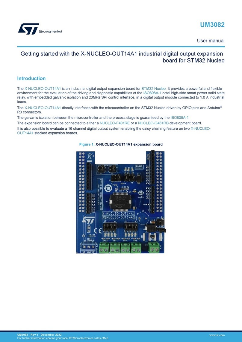
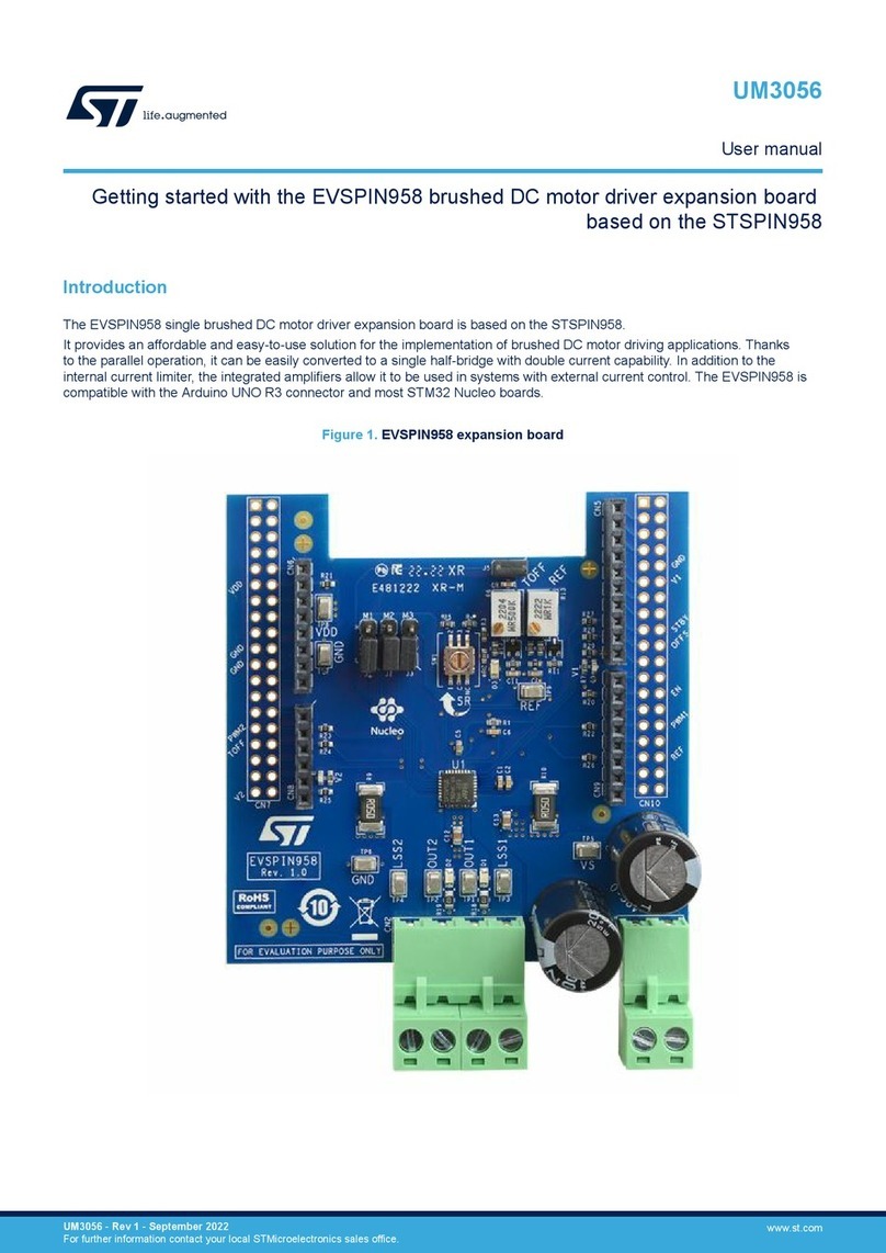
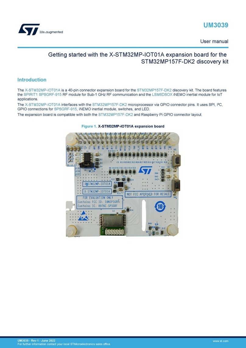
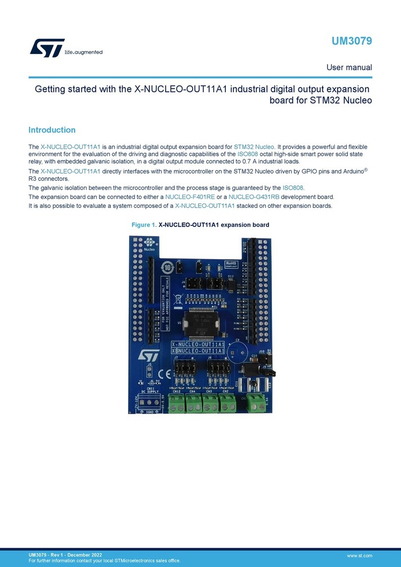
ST UM0575 User manual

February 2009 Rev 1 1/20
UM0575
User manual
STEVAL- IHT003V1, e-STARTER demonstration board
based on the ACST6 and X02
Introduction
The e-STARTER demonstration board (Figure 1) presents an innovative solution, patented
by STMicroelectronics, to reduce the power losses due to the positive thermal coefficient
(PTC) resistors in compressor starter circuits.
This solution features an ACST6 device which is used to turn off the PTC current after the
motor startup. It should be noted that the traditional PTC is still used in the electronic starter
circuit because it increases safety in case of ACST short-circuit or diode-mode failure (ref.
EN60335-1). This solution allows the starter standby losses to be decreased from typically
2.5 W to 380 mW or 40 mW, respectively for 230 V and 100 V applications.
The e-STARTER operation principle along with detailed schematics are given as well as
demonstration board performances and the method to adapt the circuit to a dedicated
compressor.
It should be noted that this board is not a "plug and play" solution. First, the PTC behavior
has to be checked (especially VPTC1 & VPTC2 levels as explained in Section 3.1) and then
the R4 resistor value has to be chosen before using the board with a compressor.
Figure 1. STEVAL- IHT003V1, e-STARTER demonstration board
AM01038v1
www.st.com

Contents UM0575
2/20
Contents
1 Operation principle . . . . . . . . . . . . . . . . . . . . . . . . . . . . . . . . . . . . . . . . . . 4
1.1 Compressor starter application . . . . . . . . . . . . . . . . . . . . . . . . . . . . . . . . . 4
1.2 Standard PTC behavior . . . . . . . . . . . . . . . . . . . . . . . . . . . . . . . . . . . . . . . 4
1.3 e-STARTER operation mode . . . . . . . . . . . . . . . . . . . . . . . . . . . . . . . . . . . 5
1.3.1 Schematics . . . . . . . . . . . . . . . . . . . . . . . . . . . . . . . . . . . . . . . . . . . . . . . 5
1.3.2 ON state . . . . . . . . . . . . . . . . . . . . . . . . . . . . . . . . . . . . . . . . . . . . . . . . . . 6
2 Board performances . . . . . . . . . . . . . . . . . . . . . . . . . . . . . . . . . . . . . . . . . 8
2.1 Maximum current . . . . . . . . . . . . . . . . . . . . . . . . . . . . . . . . . . . . . . . . . . . . 8
2.2 Standby power losses . . . . . . . . . . . . . . . . . . . . . . . . . . . . . . . . . . . . . . . . 8
2.3 Fast transient voltages . . . . . . . . . . . . . . . . . . . . . . . . . . . . . . . . . . . . . . . . 9
2.4 Surge voltages . . . . . . . . . . . . . . . . . . . . . . . . . . . . . . . . . . . . . . . . . . . . . . 9
2.5 Reliability and safety . . . . . . . . . . . . . . . . . . . . . . . . . . . . . . . . . . . . . . . . 10
3 Getting started . . . . . . . . . . . . . . . . . . . . . . . . . . . . . . . . . . . . . . . . . . . . . 12
3.1 Voltage level setting . . . . . . . . . . . . . . . . . . . . . . . . . . . . . . . . . . . . . . . . . 12
3.2 Connections . . . . . . . . . . . . . . . . . . . . . . . . . . . . . . . . . . . . . . . . . . . . . . . 13
4 Conclusion . . . . . . . . . . . . . . . . . . . . . . . . . . . . . . . . . . . . . . . . . . . . . . . . 14
Appendix A Component layout and printed circuit board . . . . . . . . . . . . . . . . . 15
Appendix B Bill of material . . . . . . . . . . . . . . . . . . . . . . . . . . . . . . . . . . . . . . . . . . 17

UM0575 List of figures
3/20
List of figures
Figure 1. STEVAL- IHT003V1, e-STARTER demonstration board . . . . . . . . . . . . . . . . . . . . . . . . . . . 1
Figure 2. Compressor starter application. . . . . . . . . . . . . . . . . . . . . . . . . . . . . . . . . . . . . . . . . . . . . . . 4
Figure 3. PTC operation, no RUN cap. (compressor OFF time > 10' mains: 198 V RMS) . . . . . . . . . 5
Figure 4. PTC operation with RUN cap.(compressor OFF time < 1' mains: 264 V RMS) . . . . . . . . . . 5
Figure 5. e-STARTER schematics . . . . . . . . . . . . . . . . . . . . . . . . . . . . . . . . . . . . . . . . . . . . . . . . . . . . 6
Figure 6. Voltage spikes at zero current . . . . . . . . . . . . . . . . . . . . . . . . . . . . . . . . . . . . . . . . . . . . . . . 7
Figure 7. PTC turnoff . . . . . . . . . . . . . . . . . . . . . . . . . . . . . . . . . . . . . . . . . . . . . . . . . . . . . . . . . . . . . . 7
Figure 8. e-STARTER maximum current versus conduction time . . . . . . . . . . . . . . . . . . . . . . . . . . . . 8
Figure 9. Spurious e-STARTER triggering with a 2 kV surge (230 V compressor) . . . . . . . . . . . . . . 10
Figure 10. e-STARTER voltage limited to 648 V thanks to the RUN capacitor
(2 kV IEC61000-4-5 surge). . . . . . . . . . . . . . . . . . . . . . . . . . . . . . . . . . . . . . . . . . . . . . . . . 10
Figure 11. VPTC1 and VPTC2 definitions . . . . . . . . . . . . . . . . . . . . . . . . . . . . . . . . . . . . . . . . . . . . . . 12
Figure 12. e-STARTER connections . . . . . . . . . . . . . . . . . . . . . . . . . . . . . . . . . . . . . . . . . . . . . . . . . . 13
Figure 13. e-STARTER topside silk screen . . . . . . . . . . . . . . . . . . . . . . . . . . . . . . . . . . . . . . . . . . . . . 15
Figure 14. e-STARTER SMD components layout (bottom view) . . . . . . . . . . . . . . . . . . . . . . . . . . . . . 16
Figure 15. e-STARTER copper side (bottom view, dimensions in cm) . . . . . . . . . . . . . . . . . . . . . . . . 16

Operation principle UM0575
4/20
1 Operation principle
1.1 Compressor starter application
Single-phase induction motors, used for compressor control, use an auxiliary winding. This
winding permits a higher torque to be applied at startup. The most popular method to control
the start winding is to add a positive temperature coefficient (PTC) resistor in series with this
winding and the thermostat (Figure 2). Then, each time the thermostat is closed, the current
flows through the start winding and begins to heat the PTC. After a few hundreds of
milliseconds, the PTC value rapidly increases from a few W to several tens of kW. This
results in reducing the start winding current to a few tens of mA. This winding can then be
considered as open. The PTC then behaves like a switch in OFF state, but with a high
leakage current, resulting in high power losses (approx. 2.5 W).
Figure 2 gives the typical schematics of this application where a run or a start capacitor can
be connected in parallel (point 1) or in series (point 2) respectively with the PTC.
1.2 Standard PTC behavior
The transition between PTC ON and OFF states brings a voltage increase across this
variable resistor. Figure 3 and Figure 4 show two oscillograms of the same PTC in two
different operating conditions, for a 230 V compressor which can use both a start and run
capacitor. We see that, at the end of the PTC conduction, the voltage across it reaches
approximately 250 V (refer to "VPTC_OFF" indication). This voltage level is similar whatever
the operating conditions are (min or max RMS line voltage, run capacitor or not, etc.). The
PTC could be turned off as soon as this level has been reached. Section 1.3 explains how to
implement an electronic solution to achieve this function.
Figure 2. Compressor starter application
04#
2%3)34/2
RUNSTART
THERMOSTAT
4C
+LIXON
#
04#
2%3)34/2
RUNSTART
THERMOSTAT
4C
+LIXON
#
!-V

UM0575 Operation principle
5/20
1.3 e-STARTER operation mode
1.3.1 Schematics
Figure 5 gives the typical schematics of an "e-STARTER" for a 230 V application. The
demonstration board presented here also features some optional pads to add a snubber
(components R6 and C4) as shown in Appendix A and B. The figure also gives the names of
the main electrical parameters which will be detailed in the following sections.
The traditional PTC resistor has to be connected between the "START" and the "PTC"
solder pads (refer also to Section 3.2).
Note: The C3 capacitor is not soldered on the breadboards. It can be added if one wants to
evaluate its impact on board immunity.
Figure 3. PTC operation, no RUN cap.
(compressor OFF time > 10' mains:
198 V RMS)
Figure 4. PTC operation with RUN
cap.(compressor OFF time < 1'
mains: 264 V RMS)
VPTC(100V/div)
IPTC(10A/div) VPTC_OFF
VPTC(100V/div)
IPTC(10A/div)
VPTC (100 V/div)
IPTC(10 A/div) VPTC_OFF
AM00899v1
V
PTC
(100V/div)
V
PTC_OFF
I
PTC
(10A/div)
AM00900v1

Operation principle UM0575
6/20
1.3.2 ON state
As soon as the mains voltage is applied:
●M1 is OFF because the voltage drop across the PTC is not high enough to reach the
DZ1 clamping level
●T2 is then turned on, thanks to the gate current provided by R2
●T1 is turned on thanks to the gate current provided by T2
Both T1 and the PTC are then ON.
At each zero-current crossing point, the ACST6 turns off. The reapplied voltage across
T1/T2 triggers back T1 which results in some voltage spikes at each zero-current crossing
point (typically around 40 V as shown in Figure 6 for a 230 V compressor).
Applying the click test of norm EN55014, the noise duration could last more than 200 ms
(depending on the type of compressor and PTC). The individual spikes last a few hundreds
of microseconds and are spaced at intervals of 10 ms, so the limits of continuous
disturbance are applicable. Since the spike peaks are less than 100 V, the e-STARTER
solution should fulfill the requirements of EN55014. It should be noted that tests results
greatly depend on the compressor used during the tests.
Figure 5. e-STARTER schematics
2
#
N
2
K
2
K
4
!#34
":8#
$:
!
#
#
N
1
0-"4!
2
K
4
8.
-
--"&
2
K
2
$
.
1
0-"4!
*
34!24
*
04#
*
25.
)#
$&
$
.
2
-%'
#
N
'.$
2
#
N
!-V

UM0575 Operation principle
7/20
When the PTC conduction time has been sufficient to start the compressor, its voltage
suddenly rises. This voltage rise is sensed by the R3/R4 divisor bridge.
If the level is higher than the DZ1 clamping level, the thyristor, consisting of Q1 and Q2, is
latched. M1 is then turned on.
As M1 is ON, there is no more gate current to trigger T2, so T1 also stays OFF. The PTC is
then turned off.
No more current circulates through the PTC, thus no power is dissipated in it.
Figure 7 shows the typical behavior of this circuit. The C1 capacitor voltage gives an image
of the PTC voltage. When its value reaches the DZ1 clamping level (15 V), the MOS gate is
latched to 15 V. The PTC is then turned off (refer to the IA ACST6 current waveform).
Figure 6. Voltage spikes at zero current
Figure 7. PTC turnoff
I
A
(5A/div)
V
AK
(20V/div)
I
A
(5 A/div)
V
AK
(20 V/div)
AM00902v1
I
A
(5A/div)
V
C2
(10V/div)
V
C1
(10V/div)
AM00903v1

Board performances UM0575
8/20
2 Board performances
2.1 Maximum current
During e-STARTER conduction, the power losses are similar to those of the standard PTC
solution as the same current circulates through this resistor. The only difference is that a
small part of the voltage is also held by T1.
In the case of an ACST6, its forward voltage drop can be considered to be a constant
forward voltage, Vt0, of at worst 0.8 V and a dynamic resistance, Rd, of at worst 80 m. So
even with a 10 A peak current, the voltage drop is less than 1 V.
This forward voltage drop should be taken into account mainly to evaluate the junction
temperature elevation of the semiconductor switch.
For an ACST6 in the TO220AB package, without any heatsink, this junction temperature
elevation is equal to:
●30° C after a 5 A RMS current during 3 s (worst case of typical 100 V/60 Hz
compressors)
●50° C after an 11 A RMS current during 0.5 s (worst case of typical 230 V/50 Hz
compressors)
This ensures that TJremains below its maximum allowed temperature (125° C), even with a
75° C initial temperature. Figure 8 gives the maximum repetitive RMS current that the
ACST6-7ST can withstand without any heatsink. This curve is given for 40° C and 75° C
ambient temperatures. As with the e-STARTER solution, the heating time of the PTC is not
long enough to warm the electronic devices, so the 40° C curve is closer to the real
e-STARTER operating conditions.
2.2 Standby power losses
During e-STARTER standby, the losses are caused only by the resistors, which are still
connected to the mains voltage. Indeed, the ACST leakage current is in practice very much
lower than 20 µA so that the resulting losses can be neglected.
Figure 8. e-STARTER maximum current versus conduction time
E3TARTER#ONDUCTION4IMES
-AX2-3CURRENT!
4A#2EP
4A#2EP
!-V

UM0575 Board performances
9/20
The two resistors which are mainly dissipating power at standby are:
●R2 - used to provide T2 with gate current during the e-STARTER on state
●R3 - used to sense the voltage level across the PTC
As R2 is connected just behind the diodes’ bridges, the VAK voltage is applied across it, in
full-wave mode. R3 senses only half the voltage across the PTC and T1. This voltage is also
equal to VAK as T1 is OFF, and so no current is circulating through the PTC.
We can neglect the voltage drops of M1 and of C1, which are lower than 0.6 V and 16 V
respectively. The power losses, dissipated by the two resistors, are given by the following
equations:
Equation 1
An example with R2 = 470 kΩand R3 = 510 kΩgives:
●For a 230 V / 50 Hz application using a run capacitor, VAK can reach up to 350 V RMS.
The overall power losses then equal 380 mW.
●For a 100 V / 60 Hz application using or not a run capacitor, VAK stays around the line
voltage, i.e at worst 115 V RMS. The overall power losses then equal 41 mW.
2.3 Fast transient voltages
Immunity tests, as described by the IEC 61000-4-4 standard, have been performed with the
schematics of Figure 5, connected in series with a compressor without a RUN or START
capacitor. e-STARTER spurious triggerings have not been detected with spikes up to 2 kV.
This high immunity level has been reached thanks to:
●the high dV/dt capability of the ACST6
●the improved dV/dt capability of the very sensitive SCR X0202M (20 µA < Igt < 50 µA)
thanks to the fact that its gate is short-circuited to the cathode via M1 in OFF state, and
also thanks to the R6-C4 snubber circuit
●the RGK (R7) resistor which is added on the ACST6 device to derivate the current
provided by R2 when M1 is ON
●the immunity provided by the layout of the printed circuit board (refer to Figure 15)
It should be noted that spurious triggering of the e-STARTER is not a problem as such
behavior is not seen by the end user, and as these turn-ons do not lead to any component
failure.
2.4 Surge voltages
The ACST6 device is an overvoltage protected device which means that it can be used
without any varistor in parallel with its terminals. If a high energy surge is applied to the
⎪
⎪
⎩
⎪
⎪
⎨
⎧
⋅=
=
3R
V
2
1
P
2R
V
P
2
AK
3R
2
AK
2R

Board performances UM0575
10/20
mains, as described in the IEC 61000-4-5 standard, when the e-STARTER is off, two cases
can occur:
●A no-run capacitor is connected across the e-STARTER: the surge voltage is then
entirely held by the ACST6. If the energy is high enough, the leakage current of the
device can exceed its break-over level, leading to a turn-on of the e-STARTER lasting
at worst 10 ms (refer to Figure 9).
●A run capacitor is used: the surge energy is absorbed by this capacitor. The voltage
level is then limited below 1 kV, which is the typical clamping level of the ACST6. No
spurious turn-on occurs in this case (refer to Figure 10).
It should be noted that in case of a spurious triggering in break-over mode, the ACST6
current is limited by the START winding inductance. The current value is then typically in the
range of 2 A. This is far below the level guaranteed with ACST6, where a 47 Ωload can be
used in such operation mode (refer to the ACST6 datasheet). With a 2 kV surge, the peak
current then equals 40 A in this case.
2.5 Reliability and safety
Reliability tests have been performed with ACST6-7ST samples submitted to a current
shape equivalent to an inrush current of 11 A RMS during 0.5 s. No parameter evolution of
these samples has been detected after 450,000 cycles, which is representative of the
lifetime of a refrigerator. This result demonstrates the excellent capability of these 6 A
products even for applications with high inrush currents.
Concerning safety, the EN6033561 standard imposes the consideration of short-circuit or
diode-mode failures of all silicon power switches involved in safety features. The failure of an
entire e-STARTER cannot lead to safety issues (electrical or mechanical shock, fire). If the
e-STARTER power switch dies in short-circuit or diode-mode, the start winding current is still
limited by the PTC. The start winding is then protected and the compressor still works.
Indeed, the starter function is still ensured by the PTC. The only drawback is that the
standby losses increase back to 2.5 W.
Figure 9. Spurious e-STARTER triggering
with a 2 kV surge (230 V
compressor)
Figure 10. e-STARTER voltage limited to 648 V
thanks to the RUN capacitor (2 kV
IEC61000-4-5 surge)
VAK
IA
VAK
IA
AM00905v1
+ 648V
VAK
VMAINS
IA
+ 648V
VAK
VMAINS
IA
AM00906v1

UM0575 Board performances
11/20
If a failure occurs on the control side, leading to a short-circuit of both the power switch and
the PTC, then the start winding could be damaged as its current would not be limited. The
solution is then to use a thin copper track (Figure 15) between the start winding terminal and
the e-STARTER control circuit. For example, a 130 µm track conducts the 1mA peak current
in normal operation but blows if the whole start winding current, at least equal to 5 A RMS,
circulates through it. The ACST6 then remains on the entire time the thermostat switch is
closed. The behavior is the same as a standard PTC, without the power saving function of
the e-STARTER.

Getting started UM0575
12/20
3 Getting started
3.1 Voltage level setting
To make the demonstration board operate with a given compressor-PTC couple, the only
thing to do is to check the divisor ratio of the R3/R4 resistors bridge.
First, the PTC voltage level, which is representative of a long enough START winding
activation, has to be defined. This level is called "VPTC-OFF".
To proceed, we propose to measure the PTC peak voltages in ON and in OFF state for the
whole range of operation, that is:
●min and max values of the line voltage
●at least one sample of all different compressors that could be used with the
e-STARTER
●min and max values of the ambient temperature.
The PTC peak voltages in ON and in OFF state are called VPTC1 and VPTC2 respectively
(refer to the dashed lines in Figure 11).
Then, the "VPTC-OFF" level has to be chosen higher than the maximum value of VPTC1 in
order to ensure that the ACST6 has indeed been turned on at the beginning. The "VPTC-
OFF" level also has to be lower than the minimum value of VPTC2 in order to turn off the
ACST6 at the end of the required PTC conduction time.
In order to ensure a safe margin between these two levels, VPTC-OFF should be calculated
using the following equation:
Equation 2
According to Figure 4, the maximum VPTC1 level is 220 V. According to Figure 3, the
minimum VPTC2 level (198 V RMS line, no RUN cap, test conditions) equals 320 V (from the
Figure 11. VPTC1 and VPTC2 definitions
VPTC1
VPTC2
VPTC
IPTC
VPTC1
VPTC2
VPTC
IPTC
AM00907v1
2
VV
VMIN2PTCMAX1PTC
OFF_PTC
+
=

UM0575 Getting started
13/20
figure). Using Equation 2, we then choose a 250 V level for VPTC_OFF to give the end of
START winding conduction information.
To achieve this level detection, R4 has to be chosen according to the value of R3, using the
following equation:
Equation 3
where VDZ1 is the clamping level of the Zener diode and VBE_Q1 is the forward voltage drop
of the base-emitter junction of the Q1 transistor.
With R3 remaining at 510 kΩ(to reduce the power losses), VDZ1 and VBE_Q1 are 15 V and
0.6 V respectively, then R4 equals:
Equation 4
3.2 Connections
Before beginning any test, please take note of the following warnings:
1. The board has to be used by electrically-skilled technicians or engineers because the
board has to be plugged into the mains and because no insulation is used between the
mains voltage and the accessible conductive parts.
2. There is no insulation varnish on solders. Care should be taken when performing
measurements (for example, voltage probes have to be connected only when the line
and the power supply voltages are removed).
The e-STARTER has to be connected to a PTC and a compressor as shown in Figure 12,
according to the instructions given on the topside silk screen. The RUN capacitor (CRUN) is
optional and has to be used according to the compressor type. A start capacitor could also
be placed in series between the PTC and the e-STARTER.
1Q_BE1DZOFF_PTC
1DZ
VVV
V
3R4R −−
⋅=
Ω≅⋅=
−−
⋅⋅= k30106.32
6.015250
15
105104R 33
Figure 12. e-STARTER connections
Vac
Thermostat
Klixon
PTC
Compressor
e-STARTER
RUN
PTC
C
RUN
Vac
Thermostat
Klixon
PTC
Compressor
RUN
PTC
START
AM00908v1

Conclusion UM0575
14/20
4 Conclusion
This demonstration board promotes a full ST silicon kit for thermostat applications and
allows users to:
●check the immunity of our solution
●easily check the efficiency gains
●adapt the hardware for dedicated compressors & PTCs.
The e-STARTER allows the designers of cold appliances to upgrade the efficiency class of
refrigerators or freezers with a very low cost solution. This solution allows the starter
standby losses to be decreased from typically 2.5 W to 380 mW or 40 mW, respectively for
230 V and 100 V applications. The high reliability and immunity of this circuit are ideally
suited to the severe requirements of a refrigerator or freezer application.

UM0575 Component layout and printed circuit board
15/20
Appendix A Component layout and printed circuit board
Figure 13 and Figure 14 give the layout of the components for the top and the bottom layers,
respectively. Figure 15 gives the copper side of the e-STARTER demonstration board.
Figure 13. e-STARTER topside silk screen
AM00909v1

Component layout and printed circuit board UM0575
16/20
Figure 14. e-STARTER SMD components layout (bottom view)
Figure 15. e-STARTER copper side (bottom view, dimensions in cm)
AM00910v1
AM00911v1

UM0575 Bill of material
17/20
Appendix B Bill of material
The following table gives the bill of material of the e-STARTER board for a 230 V application.
The values are given for indication as some values can be changed to adapt the voltage
level detection (R3, R4, DZ1) or to increase the board immunity (R6, C4, R7, C2, C3, R8,
C1).
Table 1. e-STARTER bill of material
Index Qty Reference Name Package Manufacturer
Manufacturer’s ordering
code / orderable part
number
1 1 TRIAC T1 TO-220 STMicroelectronics ACST6-7ST
2 1 SCR T2 SOT-223 STMicroelectronics X0202NN 5BA4
3 1 PNP transistor Q1 SOT-23 Philips PMBT2907A
4 1 NPN transistor Q2 SOT-23 Philips PMBT2222A
51 N-Channel
transistor M1 SOT-23 Fairchild MMBF170
61
Resistor620 kΩ
1/4 W 1% R1 TH,
Axial,0207
71
Resistor 470 kΩ
1/4 W 1% R2 TH,
Axial,0207
81
Resistor 510 kΩ
1/4 W 1% R3 TH,
Axial,0207
91
Resistor 30 kΩ
1/4 W 1% R4 TH,Axial,020,
pitch 2,5
10 1 Resistor 10 kΩ
1/4 W 1% R5 TH,Axial,0207
11 1 Resistor 0 1/4 W R6 TH,Axial,0207
12 1 Resistor 220
1/4 W 1% R7 SMD 1206
13 1 Resistor 1 M
1/4W 1% R8 TH,Axial,0207
14 1 Ceramic capacitor
10 nF/50 V 20% C1 SMD 1206
15 1 Ceramic capacitor
10 nF/50 V 20% C2 SMD 1206
16 1 No capacitor
connected C3 SMD 1206
17 1 Capacitor 22 nF /
250 VAC C4 TH, pitch 11
18 1 Single phase
bridge rectifier DF06 DIL DB-1 WTE / GOOD-ARK DF06

Bill of material UM0575
18/20
19 1
General purpose
rectifier, 1N4007
(1000 V,1 A)
D1 DO214 SMA
20 1
Small signal
diode, 1N4148
(75 V,0.15 A)
D2 DO-35
21 1 Zener diode DZ1 DO-35 Fairchild / Vishay BZX55C 15
Table 1. e-STARTER bill of material (continued)
Index Qty Reference Name Package Manufacturer
Manufacturer’s ordering
code / orderable part
number

UM0575 Revision history
19/20
Revision history
Table 2. Document revision history
Date Revision Changes
13-Feb-2008 1 Initial release

UM0575
20/20
Please Read Carefully:
Information in this document is provided solely in connection with ST products. STMicroelectronics NV and its subsidiaries (“ST”) reserve the
right to make changes, corrections, modifications or improvements, to this document, and the products and services described herein at any
time, without notice.
All ST products are sold pursuant to ST’s terms and conditions of sale.
Purchasers are solely responsible for the choice, selection and use of the ST products and services described herein, and ST assumes no
liability whatsoever relating to the choice, selection or use of the ST products and services described herein.
No license, express or implied, by estoppel or otherwise, to any intellectual property rights is granted under this document. If any part of this
document refers to any third party products or services it shall not be deemed a license grant by ST for the use of such third party products
or services, or any intellectual property contained therein or considered as a warranty covering the use in any manner whatsoever of such
third party products or services or any intellectual property contained therein.
UNLESS OTHERWISE SET FORTH IN ST’S TERMS AND CONDITIONS OF SALE ST DISCLAIMS ANY EXPRESS OR IMPLIED
WARRANTY WITH RESPECT TO THE USE AND/OR SALE OF ST PRODUCTS INCLUDING WITHOUT LIMITATION IMPLIED
WARRANTIES OF MERCHANTABILITY, FITNESS FOR A PARTICULAR PURPOSE (AND THEIR EQUIVALENTS UNDER THE LAWS
OF ANY JURISDICTION), OR INFRINGEMENT OF ANY PATENT, COPYRIGHT OR OTHER INTELLECTUAL PROPERTY RIGHT.
UNLESS EXPRESSLY APPROVED IN WRITING BY AN AUTHORIZED ST REPRESENTATIVE, ST PRODUCTS ARE NOT
RECOMMENDED, AUTHORIZED OR WARRANTED FOR USE IN MILITARY, AIR CRAFT, SPACE, LIFE SAVING, OR LIFE SUSTAINING
APPLICATIONS, NOR IN PRODUCTS OR SYSTEMS WHERE FAILURE OR MALFUNCTION MAY RESULT IN PERSONAL INJURY,
DEATH, OR SEVERE PROPERTY OR ENVIRONMENTAL DAMAGE. ST PRODUCTS WHICH ARE NOT SPECIFIED AS "AUTOMOTIVE
GRADE" MAY ONLY BE USED IN AUTOMOTIVE APPLICATIONS AT USER’S OWN RISK.
Resale of ST products with provisions different from the statements and/or technical features set forth in this document shall immediately void
any warranty granted by ST for the ST product or service described herein and shall not create or extend in any manner whatsoever, any
liability of ST.
ST and the ST logo are trademarks or registered trademarks of ST in various countries.
Information in this document supersedes and replaces all information previously supplied.
The ST logo is a registered trademark of STMicroelectronics. All other names are the property of their respective owners.
© 2009 STMicroelectronics - All rights reserved
STMicroelectronics group of companies
Australia - Belgium - Brazil - Canada - China - Czech Republic - Finland - France - Germany - Hong Kong - India - Israel - Italy - Japan -
Malaysia - Malta - Morocco - Singapore - Spain - Sweden - Switzerland - United Kingdom - United States of America
www.st.com
This manual suits for next models
1
Table of contents
Other ST Computer Hardware manuals

ST
ST X-NUCLEO-SNK1M1 User manual

ST
ST STEVAL-DPSG474 User manual

ST
ST STDES-PFCBIDIR User manual

ST
ST STM32MP157D-DK1 User manual

ST
ST UM1472 User manual

ST
ST X-NUCLEO-STMODA1 User manual

ST
ST X-NUCLEO-OUT02A1 User manual

ST
ST X-NUCLEO-AMICAM1 User manual

ST
ST STM32 ODE User manual

ST
ST X-NUCLEO-IDS01A4 User manual

ST
ST QFN20 User manual

ST
ST I-CUBE-LRWAN User manual

ST
ST ST7LITEUS2 User manual

ST
ST X-NUCLEO-IDB05A2 User manual

ST
ST EVLKST8500GH-2 User manual

ST
ST X-NUCLEO-6283A1 User manual

ST
ST STEVAL-IFP044V1 User manual

ST
ST X-NUCLEO-IKA01A1 User manual

ST
ST STM32F4 Series Owner's manual

ST
ST X-STM32MP-MSP01 User manual