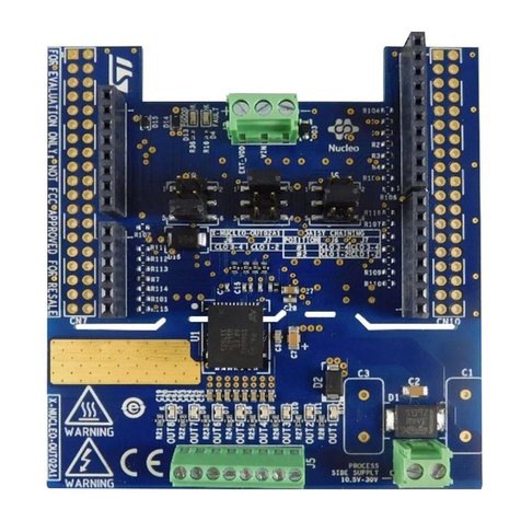
ST X-NUCLEO-OUT02A1 User manual

Introduction
The STSW-IFAPGUI is the common graphic user interface designed to facilitate the control of the IPS and IO-Link evaluation
boards based on STM32 Nucleo.
The GUI automatically detects the firmware version running on the STM32 Nucleo board connected to your laptop/PC via USB
cable.
For the X-NUCLEO-OUT02A1, the GUI works in combination with the X-CUBE-OUT02 firmware, running on the NUCLEO-
F401RE board and controlling the features of the ISO8200AQ such as the frequency and duty cycle of each output channel and
the internal status of the IC.
The GUI is available free of charge on www.st.com.
Figure 1. STSW-IFAPGUI graphical user interface
Getting started with the GUI for the X-NUCLEO-OUT02A1 expansion board
UM2509
User manual
UM2509 - Rev 1 - November 2018
For further information contact your local STMicroelectronics sales office.
www.st.com

1STSW-IFAPGUI overview
Figure 2. STSW-IFAPGUI overview
The STSW-IFAPGUI is a Windows®-based application able to control the X-CUBE-OUT02 and automatically
identify the firmware version.
The GUI can control the firmware for two X-NUCLEO-OUT02A1 boards stacked together by activating daisy
chaining via proper jumper configuration.
The GUI features:
• single or dual chip (daisy chaining) configuration
• output channel control by switching frequency (0 to 100 Hz) and duty cycle (0 to 100%)
• output enable signal control
• start/stop SPI signal sequence
• power good open drain monitoring status (ON/OFF)
• common fault open drain monitoring status (ON/OFF)
• output channel thermal fault monitoring status
UM2509
STSW-IFAPGUI overview
UM2509 - Rev 1 page 2/12

2Software installation
The STSW-IFAPGUI software is designed to run on Microsoft® Windows.
To install the GUI:
Step 1. Run Setup_ STSW-IFAPGUI.exe included in the package
Step 2. Follow the installation instructions
Figure 3. STSW-IFAPGUI installation guide
UM2509
Software installation
UM2509 - Rev 1 page 3/12

3Running the graphical user interface
3.1 Single X-NUCLEO-OUT02A1 expansion board setup
Step 1. Connect the STM32 Nucleo board flashed with X-CUBE-OUT02 to the X-NUCLEO-OUT02A1 through
the Arduino connectors.
Step 2. Connect the stacked boards to your PC/laptop USB port through a mini-USB cable.
The STM32 is supplied by 3.3 V from the USB supply and the flashed firmware starts running.
By default, in the X-NUCLEO-OUT02A1, J8 is closed between pins 5-6 and the ISO8200AQ digital side
is supplied by the same 3v3 of the micro.
Step 3. Launch the GUI from [Start]>[STMicroelectronics]>[STSW-IFAPGUI]>[MDGUI.exe]
When the application starts, the firmware running on the STM32 is automatically detected and a COM
port is opened for communication.
Step 4. Click on the GUI STM32 Nucleo icon only after it becomes blue (it is green until the firmware
identification is completed).
Figure 4. STSW-IFAPGUI selection window
After having clicked the blue icon, the Device Count window appears.
Figure 5. STSW-IFAPGUI device count
Step 5. Select "1" in the Device Count window and then click OK to activate the ISO8200AQ control window.
UM2509
Running the graphical user interface
UM2509 - Rev 1 page 4/12

Figure 6. STSW-IFAPGUI control panel, single chip
Step 6. Supply the ISO8200AQ power stage with a 24 V rail via J1 connector.
Step 7. Click on the GUI [Refresh] button to align the application board and the GUI status.
Step 8. Select the desired switching frequency and duty cycle of the output channels to be activated (ON/OFF).
Note: 0 Hz stands for channel OFF; duty cycle 100% stands for channel always ON.
Step 9. Tick the OUT_EN1 to activate the ISO8200AQ output enable signal.
Step 10. Click [Start] to activate the SPI communication between MCU and ISO8200AQ.
Now the activated output channels start switching according to the setup defined in Step 7 (green LED
D5 to D12 will be driven accordingly).
When SPI is active, the right side of the GUI (fault monitoring) is automatically updated every 500 ms.
Step 11. The output channels ON/OFF statuscan be deactivated by unticking the OUT_EN1 or by clicking
[Stop].
In the first case, the SPI communication between MCU and ISO8200AQ remains active, while in the
second case the SPI communication stops.
3.2 Multiple X-NUCLEO-OUT02A1 expansion board setup
When two X-NUCLEO-OUT02A1 expansion boards are stacked (daisy chaining), follow the procedure below.
Step 1. Set the proper configuration for J6, J7 and OUT_EN signal on the two X-NUCLEO-OUT02A1.
Step 2. Connect the STM32 Nucleo board flashed with X-CUBE-OUT02 to the two X-NUCLEO-OUT02A1
boards through the Arduino connectors.
Step 3. Follow the steps described in Section 3.1 Single X-NUCLEO-OUT02A1 expansion board setup (from
step 2 on).
UM2509
Multiple X-NUCLEO-OUT02A1 expansion board setup
UM2509 - Rev 1 page 5/12

Figure 7. STSW-IFAPGUI control panel, dual chip
Step 4. When the evaluation session finishes, stop the SPI communication, close the GUI, remove the 24 V
from J1 and disconnect the USB cable from the STM32 Nucleo board.
UM2509
Multiple X-NUCLEO-OUT02A1 expansion board setup
UM2509 - Rev 1 page 6/12

4STSW-IFAPGUI control panel for X-NUCLEO-OUT02A1
This control panel (see Figure 6) shows three main function areas:
• Output channel activation (OUT_EN, switching frequency, duty cycle)
• SPI activation (start/stop)
• Fault monitoring (power good, common fault, per-channel thermal fault)
4.1
Note:
4.2
4.3
Output channel activation
You can set the switching frequency and duty cycle driving each output channel by editing the text boxes of this
section of the GUI.
The switching frequency can be set from 0 Hz (channel always OFF) to 100 Hz.
The duty cycle can be set from 0% (channel always OFF) to 100% (channel always ON).
You can also control the ISO8200AQ output enable signal by ticking the OUE_ENx box: when ticked, the output
enable pin is forced high, otherwise it is off.
the output channel ON/OFF configuration set in the GUI is transferred to the ISO8200AQ only when the SPI
communication is activated (see next chapter).
SPI activation
The ISO8200AQ output channels are controlled by the MCU SPI.
The STSW-IFAPGUI activates/deactivates the STM32 SPI interface by clicking the start/stop button.
Although the SPI is activated by the start button, you have to tick the GUI OUT_ENx box to enable the outputs.
Fault monitoring
The ISO8200AQ can report to the MCU a wide set of information.
Voltage drop on supply rail
The supply voltage is monitored by an embedded circuitry and the power good open drain pin is activated (forced
low) when the supply voltage on J1 goes below 16.5 V.
SPI communication error (modulo-8 violation)
The internal logic controls if each SPI communication contains 8 bits on the SDI (MOSI) line. In case of violation,
the common fault pin is activated (forced low).
Communication error internal to ISO8200AQ
The internal logic controls if any communication error occurs between the ISO8200AQ logic and process stage.
The common fault is activated (forced low) in case of internal commutation error.
Output channel thermal fault
The common fault pin is forced low when one (or more) ISO8200AQ channel has triggered the thermal shutdown
threshold. The MCU recognizes which channel is in thermal fault by reading the byte sent back by the
ISO8200AQ through the SDO (MISO) line.
When SPI is active, the whole status information of the ISO8200AQ is automatically refreshed every 500 ms.
When SPI is not active, the status of ISO8200AQ can be showed on the GUI by clicking the [Refresh] button.
UM2509
STSW-IFAPGUI control panel for X-NUCLEO-OUT02A1
UM2509 - Rev 1 page 7/12

Revision history
Table 1. Document revision history
Date Version Changes
15-Nov-2018 1 Initial release.
UM2509
UM2509 - Rev 1 page 8/12

Contents
1STSW-IFAPGUI overview...........................................................2
2Software installation ...............................................................3
3Running the graphical user interface...............................................4
3.1 Single X-NUCLEO-OUT02A1 expansion board setup ................................4
3.2 Multiple X-NUCLEO-OUT02A1 expansion board setup ...............................5
4STSW-IFAPGUI control panel for X-NUCLEO-OUT02A1 .............................7
4.1 Output channel activation........................................................7
4.2 SPI activation..................................................................7
4.3 Fault monitoring................................................................7
Revision history ........................................................................8
UM2509
Contents
UM2509 - Rev 1 page 9/12

List of figures
Figure 1. STSW-IFAPGUI graphical user interface ..................................................1
Figure 2. STSW-IFAPGUI overview ............................................................2
Figure 3. STSW-IFAPGUI installation guide .......................................................3
Figure 4. STSW-IFAPGUI selection window .......................................................4
Figure 5. STSW-IFAPGUI device count ..........................................................4
Figure 6. STSW-IFAPGUI control panel, single chip .................................................5
Figure 7. STSW-IFAPGUI control panel, dual chip ..................................................6
UM2509
List of figures
UM2509 - Rev 1 page 11/12

IMPORTANT NOTICE – PLEASE READ CAREFULLY
STMicroelectronics NV and its subsidiaries (“ST”) reserve the right to make changes, corrections, enhancements, modifications, and improvements to ST
products and/or to this document at any time without notice. Purchasers should obtain the latest relevant information on ST products before placing orders. ST
products are sold pursuant to ST’s terms and conditions of sale in place at the time of order acknowledgement.
Purchasers are solely responsible for the choice, selection, and use of ST products and ST assumes no liability for application assistance or the design of
Purchasers’ products.
No license, express or implied, to any intellectual property right is granted by ST herein.
Resale of ST products with provisions different from the information set forth herein shall void any warranty granted by ST for such product.
ST and the ST logo are trademarks of ST. All other product or service names are the property of their respective owners.
Information in this document supersedes and replaces information previously supplied in any prior versions of this document.
© 2018 STMicroelectronics – All rights reserved
UM2509
UM2509 - Rev 1 page 12/12
Other manuals for X-NUCLEO-OUT02A1
3
Table of contents
Other ST Computer Hardware manuals

ST
ST I-CUBE-LRWAN User manual

ST
ST X-NUCLEO-IKA01A1 User manual

ST
ST AEK-LCD-DT028V1 User manual

ST
ST X-NUCLEO-IHM02A1 User manual

ST
ST X-NUCLEO-IHM02A1 User manual

ST
ST X-NUCLEO-IHM08M1 User manual

ST
ST X-NUCLEO-IHM01A1 User manual

ST
ST STEVAL-STWINMA2 User manual

ST
ST STM32 Nucleo User manual

ST
ST STM32WL Series User manual

ST
ST STDES-65ACFADP Specification sheet

ST
ST X-LINUX-NFC5 User manual

ST
ST X-NUCLEO-OUT06A1 User manual

ST
ST UM2168 User manual

ST
ST MotionTL User manual

ST
ST X-NUCLEO-S2915A1 User manual

ST
ST X-NUCLEO-IHM11M1 User manual
ST
ST X-NUCLEO-BNRG2A1 User manual

ST
ST STM32C0 Series User manual

ST
ST FP-LIT-BLEMESH1 User manual