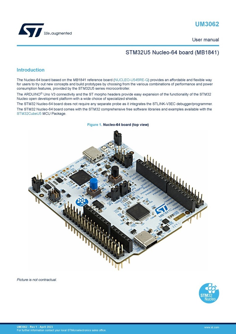
ST STM32F038 6 Series User manual

October 2016 DocID026423 Rev 2 1/21
1
STM32F038x6
Errata sheet
STM32F038x6 device limitations
Silicon identification
This document applies to the part numbers of STM32F038x6 devices listed in Table 1 and
their silicon revisions shown in Table 2.
Section 1 gives a summary and Section 2 a description of device limitations, with respect to
the device datasheet and reference manual RM0091.
Table 1. Device summary
Reference Part numbers
STM32F038x6 STM32F038C6, STM32F038F6, STM32F038G6, STM32F038K6,
STM32F038E6
Table 2. Device identification(1)
1. The REV_ID bits in the DBGMCU_IDCODE register indicate the revision code of the device
(see the reference manual for details on the revision code).
Reference Revision code marked on the device(2)
2. Refer to datasheet for details on how to identify the silicon revision code on different types of
package.
STM32F038x6 ‘A’, ‘1’
www.st.com

Contents STM32F038x6
2/21 DocID026423 Rev 2
Contents
1 Summary of device limitations . . . . . . . . . . . . . . . . . . . . . . . . . . . . . . . . 4
2 Description of device limitations . . . . . . . . . . . . . . . . . . . . . . . . . . . . . . . 6
2.1 USART . . . . . . . . . . . . . . . . . . . . . . . . . . . . . . . . . . . . . . . . . . . . . . . . . . . . 6
2.1.1 Start bit detected too soon when sampling for NACK signal from
the smartcard . . . . . . . . . . . . . . . . . . . . . . . . . . . . . . . . . . . . . . . . . . . . . . 6
2.1.2 Break request can prevent the Transmission Complete flag (TC)
from being set . . . . . . . . . . . . . . . . . . . . . . . . . . . . . . . . . . . . . . . . . . . . . 6
2.1.3 nRTS is active while RE or UE = 0 . . . . . . . . . . . . . . . . . . . . . . . . . . . . . 6
2.1.4 Consistency not checked in mode 1 of automatic baud rate
detection . . . . . . . . . . . . . . . . . . . . . . . . . . . . . . . . . . . . . . . . . . . . . . . . . 7
2.1.5 Framing error (FE) flag low upon automatic baud rate detection error . . 7
2.1.6 Communication parameters reprogramming after ATR in Smartcard
mode when SCLK is used to clock the card . . . . . . . . . . . . . . . . . . . . . . 7
2.1.7 Last byte written in TDR might not be transmitted if TE is cleared
just after writing in TDR . . . . . . . . . . . . . . . . . . . . . . . . . . . . . . . . . . . . . . 7
2.2 GPIO . . . . . . . . . . . . . . . . . . . . . . . . . . . . . . . . . . . . . . . . . . . . . . . . . . . . . 8
2.2.1 Extra consumption on GPIOs PB0..1 on 20/25/28-pin devices . . . . . . . . 8
2.2.2 GPIOx locking mechanism not working properly for GPIOx_OTYPER
register . . . . . . . . . . . . . . . . . . . . . . . . . . . . . . . . . . . . . . . . . . . . . . . . . . . 8
2.3 I2C . . . . . . . . . . . . . . . . . . . . . . . . . . . . . . . . . . . . . . . . . . . . . . . . . . . . . . . 8
2.3.1 Wrong data sampling when data set-up time (tSU;DAT) is shorter than
one I2CCLK period . . . . . . . . . . . . . . . . . . . . . . . . . . . . . . . . . . . . . . . . . 8
2.3.2 Spurious bus error detection in master mode . . . . . . . . . . . . . . . . . . . . . 9
2.3.3 10-bit slave mode: wrong direction bit value after Read header
reception . . . . . . . . . . . . . . . . . . . . . . . . . . . . . . . . . . . . . . . . . . . . . . . . . 9
2.3.4 10-bit combined with 7-bit slave mode: ADDCODE may indicate wrong
slave address detection . . . . . . . . . . . . . . . . . . . . . . . . . . . . . . . . . . . . . 10
2.3.5 Wakeup frames may not wakeup the MCU mode when STOP mode
entry follows I2C enabling . . . . . . . . . . . . . . . . . . . . . . . . . . . . . . . . . . . 10
2.3.6 Wakeup frame may not wakeup from STOP if tHD;STA is close to
HSI startup time . . . . . . . . . . . . . . . . . . . . . . . . . . . . . . . . . . . . . . . . . . . 11
2.3.7 Wrong behavior in Stop mode when wakeup from Stop mode is
disabled in I2C . . . . . . . . . . . . . . . . . . . . . . . . . . . . . . . . . . . . . . . . . . . . 11
2.3.8 10-bit master mode: new transfer cannot be launched if first part of the
address has not been acknowledged by the slave 12
2.4 SPI . . . . . . . . . . . . . . . . . . . . . . . . . . . . . . . . . . . . . . . . . . . . . . . . . . . . . . 12
2.4.1 BSY bit may stay high when SPI is disabled . . . . . . . . . . . . . . . . . . . . . 12

DocID026423 Rev 2 3/21
STM32F038x6 Contents
3
2.4.2 BSY bit may stay high at the end of a data transfer in slave mode . . . . 13
2.4.3 Wrong CRC transmitted in master mode with delayed SCK feedback . 13
2.4.4 CRC error in SPI slave mode if internal NSS changes before CRC
transfer . . . . . . . . . . . . . . . . . . . . . . . . . . . . . . . . . . . . . . . . . . . . . . . . . . 14
2.4.5 SPI CRC corrupted upon DMA transaction completion by another
peripheral . . . . . . . . . . . . . . . . . . . . . . . . . . . . . . . . . . . . . . . . . . . . . . . . 14
2.4.6 Corrupted last bit of data and/or CRC, received in master mode with
delayed SCK feedback . . . . . . . . . . . . . . . . . . . . . . . . . . . . . . . . . . . . . 14
2.4.7 Packing mode limitation at reception . . . . . . . . . . . . . . . . . . . . . . . . . . . 15
2.4.8 In I2S slave mode: WS level must be set by the external master when
enabling the I2S . . . . . . . . . . . . . . . . . . . . . . . . . . . . . . . . . . . . . . . . . . . 16
2.5 RTC . . . . . . . . . . . . . . . . . . . . . . . . . . . . . . . . . . . . . . . . . . . . . . . . . . . . . 16
2.5.1 Spurious tamper detection when disabling the tamper channel . . . . . . . 16
2.5.2 A tamper event preceding the tamper detect enable not detected . . . . 16
2.5.3 RTC calendar registers are not locked properly . . . . . . . . . . . . . . . . . . 17
2.6 ADC . . . . . . . . . . . . . . . . . . . . . . . . . . . . . . . . . . . . . . . . . . . . . . . . . . . . . 17
2.6.1 Overrun flag not set if EOC reset coincides with new conversion end . 17
2.6.2 ADEN bit cannot be set immediately after the ADC calibration . . . . . . . 17
2.7 IWDG . . . . . . . . . . . . . . . . . . . . . . . . . . . . . . . . . . . . . . . . . . . . . . . . . . . . 18
2.7.1 RVU, PVU and WVU flags are not reset in STOP mode . . . . . . . . . . . . 18
2.7.2 RVU, PVU and WVU flags are not reset with low-frequency APB . . . . . 18
3 Revision history . . . . . . . . . . . . . . . . . . . . . . . . . . . . . . . . . . . . . . . . . . . 19

Summary of device limitations STM32F038x6
4/21 DocID026423 Rev 2
1 Summary of device limitations
The following table gives a quick references to all documented device limitations of
STM32F038x6 and their status:
A = workaround available
N = no workaround available
P = partial workaround available
“-” grayed = limitation not existing / limitation fixed
Table 3. Summary of device limitations
Function Section Limitation
Status
Rev. ‘A’, ‘1’
USART
2.1.1 Start bit detected too soon when sampling for NACK signal from the
smartcard N
2.1.2 Break request can prevent the Transmission Complete flag (TC) from
being set A
2.1.3 nRTS is active while RE or UE = 0 A
2.1.4 Consistency not checked in mode 1 of automatic baud rate detection N
2.1.5 Framing error (FE) flag low upon automatic baud rate detection error A
2.1.6 Communication parameters reprogramming after ATR in Smartcard mode
when SCLK is used to clock the card A
2.1.7 Last byte written in TDR might not be transmitted if TE is cleared just after
writing in TDR A
GPIO
2.2.1 Extra consumption on GPIOs PB0..1 on 20/25/28-pin devices A
2.2.2 GPIOx locking mechanism not working properly for GPIOx_OTYPER
register P
I2C
2.3.1 Wrong data sampling when data set-up time (tSU;DAT) is shorter than one
I2CCLK period P
2.3.2 Spurious bus error detection in master mode A
2.3.3 10-bit slave mode: wrong direction bit value after Read header reception A
2.3.4 10-bit combined with 7-bit slave mode: ADDCODE may indicate wrong
slave address detection N
2.3.5 Wakeup frames may not wakeup the MCU mode when STOP mode entry
follows I2C enabling A
2.3.6 Wakeup frame may not wakeup from STOP if tHD;STA is close to HSI
startup time P
2.3.7 Wrong behavior in Stop mode when wakeup from Stop mode is disabled in
I2C A
2.3.8 10-bit master mode: new transfer cannot be launched if first part of the
address has not been acknowledged by the slave A

DocID026423 Rev 2 5/21
STM32F038x6 Summary of device limitations
5
SPI
2.4.1 BSY bit may stay high when SPI is disabled A
2.4.2 BSY bit may stay high at the end of a data transfer in slave mode A
2.4.3 Wrong CRC transmitted in master mode with delayed SCK feedback A
2.4.4 CRC error in SPI slave mode if internal NSS changes before CRC transfer A
2.4.5 SPI CRC corrupted upon DMA transaction completion by another
peripheral P
2.4.6 Corrupted last bit of data and/or CRC, received in master mode with
delayed SCK feedback A
2.4.7 Packing mode limitation at reception N
2.4.8 In I2S slave mode: WS level must be set by the external master when
enabling the I2S A
RTC
2.5.1 Spurious tamper detection when disabling the tamper channel P
2.5.2 A tamper event preceding the tamper detect enable not detected A
2.5.3 RTC calendar registers are not locked properly A
ADC
2.6.1 Overrun flag not set if EOC reset coincides with new conversion end A
2.6.2 ADEN bit cannot be set immediately after the ADC calibration A
IWDG
2.7.1 RVU, PVU and WVU flags are not reset in STOP mode A
2.7.2 RVU, PVU and WVU flags are not reset with low-frequency APB N
Table 3. Summary of device limitations (continued)
Function Section Limitation
Status
Rev. ‘A’, ‘1’

Description of device limitations STM32F038x6
6/21 DocID026423 Rev 2
2 Description of device limitations
The following sections describe device limitations and provide workarounds if available.
They are grouped by device functions.
2.1 USART
2.1.1 Start bit detected too soon when sampling for NACK signal from
the smartcard
Description
In the ISO7816, when a character parity error is incorrect, the smartcard receiver shall
transmit a NACK error signal at (10.5 +/- 0.2) etu after the character START bit falling edge.
In this case, the USART transmitter should be able to detect correctly the NACK signal by
sampling at (11.0 +/-0.2) etu after the character START bit falling edge.
The USART peripheral used in smartcard mode doesn't respect the (11 +/-0.2) etu timing,
and when the NACK falling edge arrives at 10.68 etu or later, the USART might misinterpret
this transition as a START bit even if the NACK is correctly detected.
Workaround
None
2.1.2 Break request can prevent the Transmission Complete flag (TC)
from being set
Description
After the end of transmission of a data (D1), the Transmission Complete (TC) flag will not be
set in the following conditions:
•CTS hardware flow control is enabled.
•D1 is being transmitted.
•A break transfer is requested before the end of D1 transfer.
•nCTS is de-asserted before the end of transfer of D1.
Workaround
If the application needs to detect the end of transfer of the data, the break request should be
done after making sure that the TC flag is set.
2.1.3 nRTS is active while RE or UE = 0
Description
The nRTS line is driven low as soon as RTSE bit is set even if the USART is disabled (UE =
0 or the receiver is disabled (RE = 0) i.e. not ready to receive data.

DocID026423 Rev 2 7/21
STM32F038x6 Description of device limitations
18
Workaround
Configure the I/O used for nRTS as alternate function after setting the UE and RE bits.
2.1.4 Consistency not checked in mode 1 of automatic baud rate
detection
Description
In mode 1 (ABRMOD = 01) of automatic baud rate detection, the Start bit then the first data
bit duration is measured. If either single value measured is within an allowed range, the
baud rate detection ends with success, even if the two values are inconsistent. As a
consequence, the automatic baud rate detection result in mode 1 is reliable with regular
input frames but not with abnormal frames.
Workaround
None
2.1.5 Framing error (FE) flag low upon automatic baud rate detection error
Description
When the ABRE flag is set to indicate an error of automatic baud rate detection, the framing
error flag FE remains low although it should go high.
Workaround
Poll exclusively the ABRE flag when checking for automatic baud rate error.
2.1.6 Communication parameters reprogramming after ATR in Smartcard
mode when SCLK is used to clock the card
Description
If the USART is used in Smartcard mode and the card cannot use the default
communication parameters after Answer To Reset and doesn’t support clock stop, it is not
possible to use SCLK to clock the card. This is due to the fact that the USART and its clock
output must be disabled while reprogramming some of the parameters.
Workaround
Use another clock source to clock the card (e.g. a timer output programmed to the desired
clock frequency).
2.1.7 Last byte written in TDR might not be transmitted if TE is cleared
just after writing in TDR
Description
If the USART clock source is slow (for example LSE) and TE bit is cleared immediately after
the last write to TDR, the last byte will probably not be transmitted.
Workarounds

Description of device limitations STM32F038x6
8/21 DocID026423 Rev 2
1. Wait until TXE flag is set before clearing TE bit
2. Wait until TC flag is set before clearing TE bit
2.2 GPIO
2.2.1 Extra consumption on GPIOs PB0..1 on 20/25/28-pin devices
Description
For lower pin count devices, some GPIOs are not available on the package. The hardware
forces them to safe configuration.
In this situation the software reconfiguration of PB0..1 to analog mode opens a path
between VDDA and VDDIOx. Additional current consumption in the range of tens of µA can be
observed if VDDA is higher than VDDIOx.
Workaround
Do not reconfigure PB0..1 to the analog mode when PB0..1 GPIOs are not available on the
device.
2.2.2 GPIOx locking mechanism not working properly for GPIOx_OTYPER
register
Description
Locking of GPIOx_OTYPER[i] with i = 15..8 depends from setting of GPIOx_LCKR[i-8] and
not from GPIOx_LCKR[i]. GPIOx_LCKR[i-8] is locking GPIOx_OTYPER[i] together with
GPIOx_OTYPER[i-8]. It is not possible to lock GPIOx_OTYPER[i] with i = 15...8, without
locking also GPIOx_OTYPER[i-8].
Workaround
The only way to lock GPIOx_OTYPER[i] with i=15..8 is to lock also GPIOx_OTYPER[i-8].
2.3 I2C
2.3.1 Wrong data sampling when data set-up time (tSU;DAT) is shorter than
one I2CCLK period
Description
The I²C-bus specification and user manual specify a minimum data set-up time (tSU;DAT) as:
•250 ns in Standard mode
•100 ns in Fast mode
•50 ns in Fast mode Plus
The I²C-bus SDA line is not correctly sampled when tSU;DAT is smaller than one I2CCLK
(I²C-bus peripheral clock) period: the previous SDA value is sampled instead of the current
one. This can result in a wrong receipt of slave address, data byte, or acknowledge bit.

DocID026423 Rev 2 9/21
STM32F038x6 Description of device limitations
18
Workaround
Increase the I2CCLK frequency to get I2CCLK period within the transmitter minimum data
set-up time. Alternatively, increase transmitter’s minimum data set-up time.
2.3.2 Spurious bus error detection in master mode
Description
In master mode, a bus error can be detected by mistake, so the BERR flag can be wrongly
raised in the status register. This will generate a spurious Bus Error interrupt if the interrupt
is enabled. A bus error detection has no effect on the transfer in master mode, therefore the
I2C transfer can continue normally.
Workaround
If a bus error interrupt is generated in master mode, the BERR flag must be cleared by
software. No other action is required and the on-going transfer can be handled normally.
2.3.3 10-bit slave mode: wrong direction bit value after Read header
reception
Description
Under specific conditions, the transfer direction bit DIR (bit 16 of status register I2C_ISR) is
low instead of high after reception of the 10-bit addressing Read header. Nevertheless, the
I2C operates correctly in slave transmission mode, and data can be sent using the TXIS
flag.
To see the limitation, all the following conditions have to be fulfilled:
•I2C has to be configured in 10-bit addressing mode (OA1MODE is set in the I2C_OAR1
register).
•The high LSBs of the I2C slave address are equal to the 10-bit addressing Read
header value (i.e. OA1[7:3] = 11110, OA1[2] = OA1[9], OA1[1] = OA1[8] and OA1[0] = 1
in the I2C_OAR1 register).
•The I2C receives the 10-bit addressing Read header (0X 1111 0XX1) after the repeated
start condition to enter slave transmission mode.
As a result, the DIR bit is incorrect in slave mode under specific conditions.
Workaround
If possible, do not use these four values as 10-bit addresses in slave mode:
•OA1[9:0] = 0011110001
•OA1[9:0] = 0111110011
•OA1[9:0] = 1011110101
•OA1[9:0] = 1111110111
If one of these addresses is the I2C slave address, the DIR bit must not be used in the FW.

Description of device limitations STM32F038x6
10/21 DocID026423 Rev 2
2.3.4 10-bit combined with 7-bit slave mode: ADDCODE may indicate wrong
slave address detection
Description
Under specific conditions, the ADDCODE (Address match code) in the I2C_ISR register
indicates a wrong slave address.
To see the limitation, all the following conditions have to be fulfilled:
•The I2C slave address OA1 is enabled and configured in 10-bit mode (OA1EN=1 and
OA1MODE=1)
•Another 7-bit slave address is enabled and the bits 1 to 7 of the 10-bit slave address
OA1 are equal to the 7-bit slave address, i.e., one of the configurations below is set:
– OA2EN=1 and OA2MSK = 0 and OA1[7:1] = OA2[7:1]
– OA2EN=1 and OA2MSK = 1 and OA1[7:2] = OA2[7:2]
– OA2EN=1 and OA2MSK = 2 and OA1[7:3] = OA2[7:3]
– OA2EN=1 and OA2MSK = 3 and OA1[7:4] = OA2[7:4]
– OA2EN=1 and OA2MSK = 4 and OA1[7:5] = OA2[7:5]
– OA2EN=1 and OA2MSK = 5 and OA1[7:6] = OA2[7:6]
– OA2EN=1 and OA2MSK = 6 and OA1[7] = OA2[7]
– OA2EN=1 and OA2MSK = 7
– GCEN=1 and OA1[7:1] = 0b0000000
– ALERTEN=1 and OA1[7:1] = 0b0001100
– SMBDEN=1 and OA1[7:1] = 0b1100001
– SMBHEN=1 and OA1[7:1] = 0b0001000
•The master starts a transfer addressed to the 10-bit slave address OA1.
As a result, after the address reception, the ADDCODE value is OA1[7:1] equal to the 7-bit
slave address, instead of 0b11110 & OA1[9:8].
Workaround
None. If several slave addresses are enabled, mixing 10-bit and 7-bit addresses, the 10-bit
Slave address OA1 [7:1] must not be equal to the 7-bit slave address.
2.3.5 Wakeup frames may not wakeup the MCU mode when STOP mode
entry follows I2C enabling
Description
If the I2C is enabled (PE = 1) and wakeup from STOP enabled in I2C (WUPEN=1) while a
transfer occurs on the I2C bus and STOP mode is entered during the same transfer while
SCL=0, the I2C is not able to detect the following START condition. This means that if the
I2C is addressed, it will not wake up the MCU and this address is not acknowledged.
Workaround
After enabling the I2C (PE is set to 1), wait for a temporization before entering STOP mode,
to ensure that the eventual on-going frame is finished.

DocID026423 Rev 2 11/21
STM32F038x6 Description of device limitations
18
2.3.6 Wakeup frame may not wakeup from STOP if tHD;STA is close to
HSI startup time
Description
Under specific conditions and if the START condition hold time tHD;STA duration is very close
to the HSI start-up time duration, the I2C is not able to detect the address match and wake
up the MCU from STOP.
To see the limitation, one of the conditions listed below has to be met:
1. Timeout detection is enabled (TIMOUTEN=1 or TEXTEN=1) and the frame before the
wakeup frame is abnormally finished due to a I2C Timeout detection (TIMOUT=1).
2. The slave arbitration is lost during the frame before the wakeup frame (ARLO=1).
3. The MCU enters STOP mode while another slave is addressed, after the address
phase and before the STOP condition (BUSY=1).
4. The MCU is in STOP mode and another slave is addressed before the I2C is
addressed.
Note: The last conditions 2, 3 and 4 can occur only in a multi-slave network.
In STOP mode, the HSI is switched on by the I2C when a START condition is detected (SDA
falling edge while SCL is high). The HSI is used to receive the address. HSI is switched off
after the address reception if received address is not the I2C slave address. If one of the
conditions above is met and if the SCL falling edge following the START condition occurs on
the first cycle of the I2CCLK clock (HSI), the address reception is not correctly done and the
address match wakeup interrupt is not generated.
Workaround
None at MCU level.
If the wakeup frame is not acknowledged by the I2C and if the master can program the
duration of the START hold time: the master should decrease or increase the START
condition hold time for more than one HSI period and resend the wakeup frame.
2.3.7 Wrong behavior in Stop mode when wakeup from Stop mode is
disabled in I2C
Description
When wakeup from Stop mode is disabled in I2C (WUPEN = 0) and the MCU enters Stop
mode while a transfer is on going on the bus, some wrong behaviors may happen:
1. BUSY flag can be wrongly set when the MCU exits Stop mode. This prevents from
initiating a transfer in master mode, as the START condition cannot be sent when
BUSY is set.
2. If clock stretching is enabled (NOSTRETCH = 0), the I2C clock SCL may be stretched
low by the I2C as long as the MCU is in Stop mode. This limitation may occur when the
Stop mode is entered during the address phase of a transfer on the I2C bus while
SCL = 0. Therefore the transfer may be stalled as long as the MCU is in Stop mode.
The probability of the occurrence depends also on the timings configuration, the
peripheral clock frequency and the I2C bus frequency.
These behaviors can occur in Slave mode and in Master mode in a multi-master topology.

Description of device limitations STM32F038x6
12/21 DocID026423 Rev 2
Workaround
Disable the I2C (PE=0) before entering Stop mode and re-enable it in Run mode.
2.3.8 10-bit master mode: new transfer cannot be launched if first part of the
address has not been acknowledged by the slave
Description
In master mode, the master automatically sends a STOP bit when the slave has not
acknowledged a byte during the address transmission.
In 10-bit addressing mode, if the first byte of the 10-bit address (5-bit header + 2 MSBs of
the address + direction bit) has not been acknowledged by the slave, the STOP bit is sent
but the START bit is not cleared and the master cannot launch a new transfer.
Workaround
When the I2C is configured in 10-bit addressing master mode and the NACKF status flag is
set in the I2C_ISR register while the START bit is still set in I2C_CR2 register, then proceed
as follows:
1. Wait for the STOP condition detection (STOPF = 1 in I2C_ISR register).
2. Disable the I2C peripheral.
3. Wait for a minimum of 3 APB cycles.
4. Enable the I2C peripheral again.
2.4 SPI
2.4.1 BSY bit may stay high when SPI is disabled
Description
The BSY flag may remain high upon disabling the SPI while operating in:
•a master transmit mode and the TXE flag is low (data register full).
•a master receive only mode (simplex receive or half-duplex bidirectional receive phase)
and an SCK strobing edge has not occurred since the transition of the RXNE flag from
low to high.
•slave mode and NSS signal is removed during the communication.
Workaround
When the SPI operates in:
•a master transmit mode, disable the SPI when TXE=1 and BSY=0.
•a master receive only mode, ignore the BSY flag.
•slave mode, do not remove the NSS signal during the communication.

DocID026423 Rev 2 13/21
STM32F038x6 Description of device limitations
18
2.4.2 BSY bit may stay high at the end of a data transfer in slave mode
Description
In slave mode, The BSY bit is not reliable to handle the end of data frame transaction due to
some bad synchronization between the CPU clock and external SCK clock provided by the
SPI master. Sporadically, the BSY bit is not cleared at the end of a data frame transfer. As a
consequence, it is not recommended to rely on the BSY bit before entering low-power mode
or modifying the SPI configuration (e.g. direction of the bidirectional mode).
Workaround
•When the SPI interface is in receive mode, the end of a transaction with the master can
be detected by the corresponding RXNE event when this flag is set after the last bit of
that transaction is sampled and the received data are stored.
•When the following sequence is used, the synchronization issue does not occur. The
BSY bit works correctly and can be used to recognize the end of any transmission
transaction (including when RXNE is not raised in bidirectional mode):
a) Write the last data into data register.
b) Poll the TXE flag till it becomes high to make sure the data transfer has started.
c) Disable the SPI interface by clearing the SPE bit while the last data transfer is on
going.
d) Poll the BSY bit till it becomes low.
Note: The second workaround can be used only when the CPU is fast enough to disable the SPI
interface after a TXE event is detected while the data frame transfer is ongoing. It cannot be
implemented when the ratio between CPU and SPI clock is low and the data frame is
particularly short. At this specific case, the timeout can be measured from the TXE event
instead by calculating a fixed number of CPU clock cycles corresponding to the time
necessary to complete the data frame transaction.
2.4.3 Wrong CRC transmitted in master mode with delayed SCK feedback
Description
In transmit transaction of the SPI/I2S interface in SPI master mode with CRC enabled, the
CRC data transmission may be corrupted if the delay of an internal feedback signal derived
from the SCK output (further feedback clock) is greater than one APB clock period. While
data and CRC bit shifting and transfer is based on an internal clock, the CRC progressive
calculation uses the feedback clock. If the delay of the feedback clock is greater than one
APB period, the transmitted CRC value may get wrong.
The main factors contributing to the delay increase are low VDD level, high temperature,
high SCK pin capacitive load and low SCK IO output speed. The SPI communication speed
has no impact.
Workaround
Set the application such as to speed up the SCK edges and / or slow down the APB clock,
through:
•configuring the SCK output GPIO so as to reach lower output impedance
•minimizing the capacitive load on the SCK output line
•configuring the APB clock speed

Description of device limitations STM32F038x6
14/21 DocID026423 Rev 2
2.4.4 CRC error in SPI slave mode if internal NSS changes before CRC
transfer
Description
When the device is configured as SPI slave, the transition of the internal NSS after the
CRCNEXT flag is set may result in wrong CRC value computed by the device and, as a
consequence, a CRC error. As a consequence, the NSS pulse mode cannot be used along
with the CRC function.
Workaround
Prevent the internal NSS signal from changing in the critical period, by configuring the
device to software NSS control if the SPI master pulses the NSS (for example in NSS pulse
mode).
2.4.5 SPI CRC corrupted upon DMA transaction completion by another
peripheral
Description
When the following conditions are all met:
•CRC function for the SPI is enabled,
•SPI transaction managed by software (as opposed to DMA) is ongoing and CRCNEXT
flag set,
•another peripheral using the same DMA channel on which the SPI is mapped
completes a DMA transfer,
the CRCNEXT bit is unexpectedly cleared and the SPI CRC calculation may be corrupted,
setting the CRC error flag.
Workaround
If possible, do not use the DMA channel, on which the SPI is mapped, by any other
peripheral.
2.4.6 Corrupted last bit of data and/or CRC, received in master mode with
delayed SCK feedback
Description
In receive transaction, in both I2S and SPI master modes, the last bit of the transacted frame
is not captured when signal provided by internal feedback loop from the SCK pin exceeds a
critical delay. The lastly transacted bit of the stored data then keeps value from the pattern
received previously. As a consequence, the last receive data bit may be wrong and/or the
CRCERR flag can be unduly asserted in the SPI mode if any data under check sum and/or
just the CRC pattern is wrongly captured. At lower APB frequencies, the I2S mode is more
sensitive than the SPI mode, especially when odd factor of the I2S prescaler is set.
The main factors contributing to the delay increase are low VDD level, high temperature,
high SCK pin capacitive load and low SCK IO output speed. The SPI communication speed
has no impact.

DocID026423 Rev 2 15/21
STM32F038x6 Description of device limitations
18
Workaround
The following measures can be adopted, jointly or individually:
•Decrease the APB clock speed.
•Configure the IO pad of the SCK pin to be faster.
The following table gives the maximum allowable APB frequency versus GPIOx_OSPEEDR
output speed control field setting for the SCK pin, at 30pF of capacitive load.
2.4.7 Packing mode limitation at reception
Description
When the SPI is configured in the short data frame mode, the packing mode on the
reception side may not be usable. Using this feature may generate a wrong RXNE event to
an Interrupt or DMA request and so the software may read back inconsistent data with FIFO
pointers misalignment on the reception FIFO.
If the packing mode is used in reception mode, the FIFO reception threshold has to be set to
16 bits. Under those setting and conditions, when a read operation (half-word to read two
data in one APB access) takes place while the FIFO level is equal to 3/4 (new data came
before the two first ones are read), the 16-bit read decreases the FIFO level to 1/4. The
RXNE flag is not de-asserted and a new request is present to read back next two packed
data although the FIFO contains half of them only. Read and write pointers in the FIFO
become misaligned and the data is corrupted.
The worst case is the SPI slave and SPI master running in continuous mode without clock
interruption between data transfers.
In full duplex Master mode, the packing runs correctly if the SPI is working in non-
continuous mode, meaning that the SPI always transfers even number of data under 16-bit
Rx FIFO threshold, then stops the data transmission until all the data received are read back
before sending the next data. Such safe read can't be fully guaranteed if SCK signal is
continuous especially when receiver can't guarantee to exclude any 16-bit access to FIFO
when it is just ¾ occupied.
Workaround
There is no workaround in any continuous receive mode.
The only way to avoid this data corruption would be to slow down the SPI communication
clock frequency in order to provide a sufficient time to the DMA (best case) or software to
read back data in time to prevent any 16-bit FIFO reading at its critical ¾ occupancy.
Table 4. Maximum allowable APB frequency at 30pF load
OSPEEDR [1:0]
for SCK pin
Max. APB frequency
for SPI mode
[MHz]
Max. APB frequency
for I2S mode
[MHz]
11 (high) 48 48
01 (medium) 36 36
x0 (low) 28 20

Description of device limitations STM32F038x6
16/21 DocID026423 Rev 2
2.4.8 In I2S slave mode: WS level must be set by the external master when
enabling the I2S
Description
In slave mode, the WS signal level is used only to start the communication. If the I2S (in
slave mode) is enabled while the master is already sending the clock and the WS signal
level is low (for I2S protocol) or is high (for the LSB or MSB-justified mode), the slave starts
communicating data immediately. In this case, the master and slave will be desynchronized
throughout the whole communication.
Workaround
The I2S peripheral must be enabled when the external master sets the WS line at:
•High level when the I2S protocol is selected.
•Low level when the LSB or MSB-justified mode is selected.
2.5 RTC
2.5.1 Spurious tamper detection when disabling the tamper channel
Description
If the tamper detection is configured for detecting on falling-edge event (TAMPFLT[1:0]=00
and TAMPxTRG=1) and if the tamper event detection is disabled when the tamper pin is at
high level, a false detection of a tamper event occurs, which may result in the erasure of
backup registers.
Workaround
The false detection of tamper event cannot be avoided. The erasure of the backup
registerscan be avoided by setting the TAMPxNOERASE bit before clearing the TAMPxE
bit, in two separate RTC_TAMPCR write accesses.
2.5.2 A tamper event preceding the tamper detect enable not detected
Description
When the tamper detect is enabled, set in edge detection mode (TAMPFLT[1:0]=00), and
•set to active rising edge (TAMPxTRG=0): if the tamper input is already high (tamper
event already occurred) at the moment of enabling the tamper detection, the tamper
event may not be detected. The probability of detection increases with the APB
frequency.
•set to active falling edge (TAMPxTRG=1): if the tamper input is already low (tamper
event already occurred) at the moment of enabling the tamper detection, the tamper
event is not detected.
Workaround
The I/O state should be checked by software in the GPIO registers, after enabling the
tamper detection and before writing sensitive values in the backup registers, in order to
ensure that no active edge occurred before enabling the tamper event detection.

DocID026423 Rev 2 17/21
STM32F038x6 Description of device limitations
18
2.5.3 RTC calendar registers are not locked properly
Description
When reading the calendar registers with BYPSHAD=0, the RTC_TR and RTC_DR
registers may not be locked after the read of RTC_SSR register. This happens if the read of
RTC_SSR is initiated one APB clock period before the shadow registers are updated. This
can result in a non-consistency of the 3 registers. Similarly, RTC_DR register can be
updated after the read of the RTC_TR register instead of being locked.
Workaround
1. Use BYPSHAD = 1 mode (Bypass shadow registers), or
2. In case BYPSHAD = 0: read SSR again after reading SSR/TR/DR to confirm that SSR
is still the same, otherwise read the values again.
2.6 ADC
2.6.1 Overrun flag not set if EOC reset coincides with new conversion end
Description
If the EOC flag is cleared by ADC_DR register read operation or by software during the
same APB cycle in which the data from a new conversion are written in the ADC_DR
register, the overrun event duly occurs (which results in the loss of either current or new
data) but the overrun flag (OVR) may stay low.
Workaround
Clear the EOC flag through ADC_DR register read operation or by software within less than
one ADC conversion cycle period from the last conversion cycle end, so as to avoid the
coincidence with the new conversion cycle end.
2.6.2 ADEN bit cannot be set immediately after the ADC calibration
Description
At the end of the ADC calibration, an internal reset of ADEN bit occurs four ADC clock
cycles after the ADCAL bit is cleared by hardware. As a consequence, if the ADEN bit is set
within those four ADC clock cycles, it is reset shortly after by the calibration logic and the
ADC remains disabled.
Workaround
1. Keep setting the ADEN bit until the ADRDY flag goes high.
2. After the ADCAL is cleared, wait for a minimum of four ADC clock cycles before setting
the ADEN bit.

Description of device limitations STM32F038x6
18/21 DocID026423 Rev 2
2.7 IWDG
2.7.1 RVU, PVU and WVU flags are not reset in STOP mode
Description
The RVU,PVU and WVU flags of the IWDG_SR register are set by hardware after a write
access to the IWDG_RLR and the IWDG_PR registers, respectively. If the Stop mode is
entered immediately after the write access, the RVU,PVU and WVU flags are not reset by
hardware. Before performing a second write operation to the IWDG_RLR or the IWDG_PR
register, the application software must wait for the RVU, PVU and WVU flags to be reset.
However, since the RVU/PVU/WPU bit is not reset after exiting the Stop mode, the software
goes into an infinite loop and the independent watchdog (IWDG) generates a reset after the
programmed timeout period.
Workaround
Wait until the RVU, PVU and WVU flags of the IWDG_SR register are reset, before entering
the Stop mode.
2.7.2 RVU, PVU and WVU flags are not reset with low-frequency APB
Description
The RVU, PVU and WVU flags of the IWDG_SR register are set by hardware after a write
access to the IWDG_RLR and the IWDG_PR registers, respectively. If the APB clock
frequency is two times slower than the IWDG clock frequency, the RVU, PVU and WVU
flags will never be reset by hardware.
Workaround
None

DocID026423 Rev 2 19/21
STM32F038x6 Revision history
20
3 Revision history
Table 5. Document revision history
Date Revision Changes
12-Jun-2014 1 Initial release.
12-Oct-2016 2
Added:
USART:
–Section 2.1.1: Start bit detected too soon when
sampling for NACK signal from the smartcard
–Section 2.1.2: Break request can prevent the
Transmission Complete flag (TC) from being set
–Section 2.1.3: nRTS is active while RE or UE = 0
–Section 2.1.4: Consistency not checked in mode 1 of
automatic baud rate detection
–Section 2.1.5: Framing error (FE) flag low upon
automatic baud rate detection error
I2C:
–Section 2.3.2: Spurious bus error detection in master
mode
–Section 2.3.8: 10-bit master mode: new transfer
cannot be launched if first part of the address has not
been acknowledged by the slave
SPI:
–Section 2.4.1: BSY bit may stay high when SPI is
disabled
–Section 2.4.2: BSY bit may stay high at the end of a
data transfer in slave mode
–Section 2.4.3: Wrong CRC transmitted in master
mode with delayed SCK feedback
–Section 2.4.4: CRC error in SPI slave mode if internal
NSS changes before CRC transfer
–Section 2.4.5: SPI CRC corrupted upon DMA
transaction completion by another peripheral
–Section 2.4.6: Corrupted last bit of data and/or CRC,
received in master mode with delayed SCK feedback
RTC:
–Section 2.5.1: Spurious tamper detection when
disabling the tamper channel
–Section 2.5.2: A tamper event preceding the tamper
detect enable not detected
–Section 2.5.3: RTC calendar registers are not locked
properly

Revision history STM32F038x6
20/21 DocID026423 Rev 2
12-Oct-2016 2
ADC:
–Section 2.6.1: Overrun flag not set if EOC reset
coincides with new conversion end
–Section 2.6.2: ADEN bit cannot be set immediately
after the ADC calibration
IWDG:
–Section 2.7.1: RVU, PVU and WVU flags are not reset
in STOP mode
–Section 2.7.2: RVU, PVU and WVU flags are not reset
with low-frequency APB
Modified:
– Document structure
– Cover page and Table 3 organization
–GPIO: Section 2.2.1: Extra consumption on GPIOs
PB0..1 on 20/25/28-pin devices
–SPI: Section 2.4.7: Packing mode limitation at
reception
Removed:
– Appendix A (package marking drawings are now
available in the data sheet)
Table 5. Document revision history (continued)
Date Revision Changes
This manual suits for next models
11
Table of contents
Other ST Computer Hardware manuals
Popular Computer Hardware manuals by other brands

Simonds
Simonds CLP-274 Owners & safety manual

Seagate
Seagate Nytro 5350S NVMe SSD product manual

Avalue Technology
Avalue Technology ECM-TGUC user manual

PS Audio
PS Audio MultiWave II Installation and operation instructions

ekwb
ekwb EK-Quantum Vector FE RTX 3070 user guide

Cypress
Cypress CY62167DV18 Specification sheet