ST STEVAL-DPSG474 User manual

Introduction
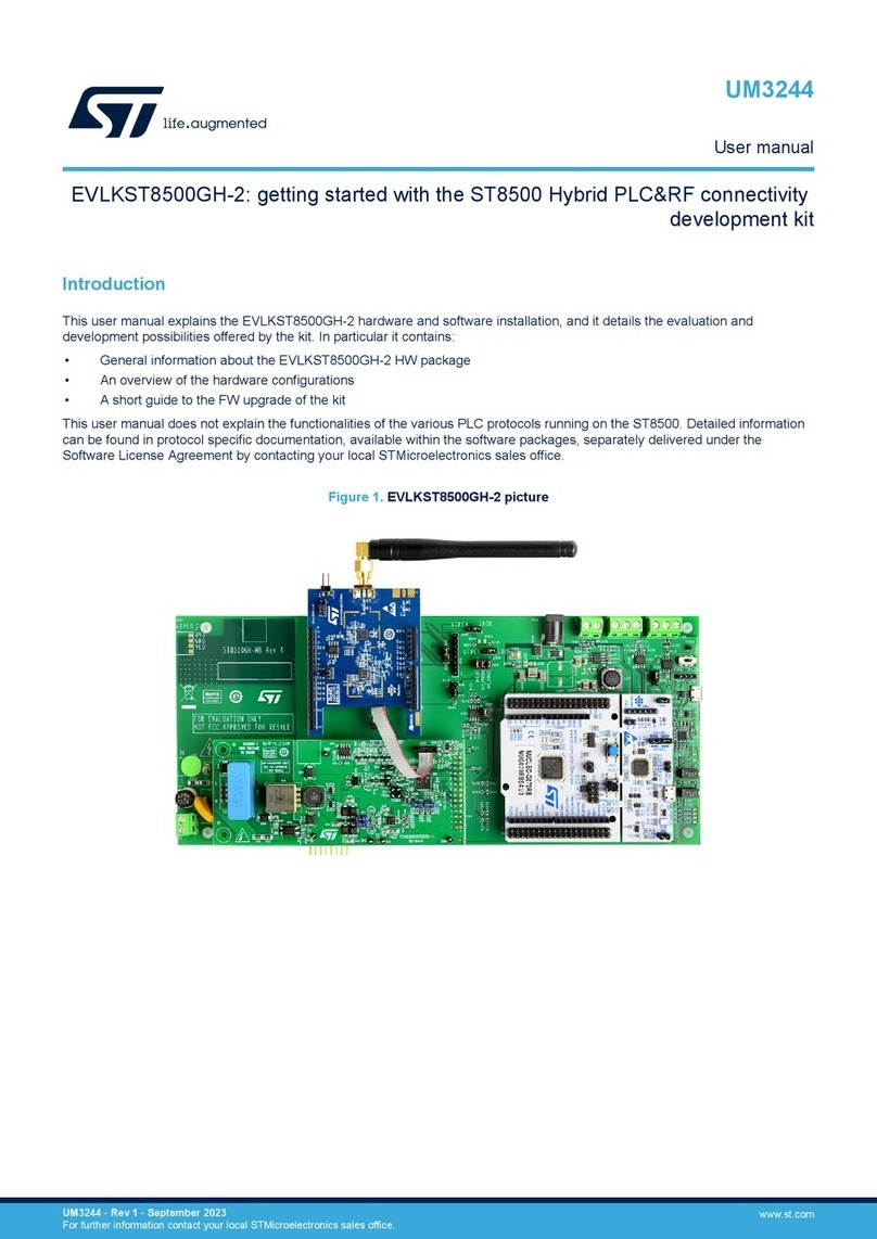
The STEVAL-DPSG474 is a digital power supply control kit. It consists of a main board, based on the
STM32G474RE microcontroller from the STM32G4 family, and an adapter board, which provides different
communication interfaces and allows programming the microcontroller through a standard 20-pin JTAG connector.
The STM32G474RE microcontroller includes the high-performance Arm® Cortex® M4 32-bit RISC core operating
at up to 170 MHz frequency, a floating point unit (FPU), a full set of DSP (digital signal processing) instructions,
and high-speed embedded memories (512 Kbytes of flash memory and 128 Kbytes of SRAM).
The device embeds peripherals that allow the mathematical/arithmetic function acceleration (CORDIC for
trigonometric functions and FMAC unit for filter functions).
The MCU offers five fast 12-bit ADCs (5 Msps), seven ultra-fast comparators, six operational amplifiers, seven
DAC channels (three external and four internal), a low-power RTC, 32-bit timers, three timers dedicated to motor
control, seven general-purpose 16-bit timers, one 16-bit low-power timer, and the high-resolution timer (HRTIM)
with 184 ps resolution, specifically designed to drive power conversion systems.
The main board embeds a standard 64-pin DIN 41612 connector for connection with a power board. It provides
all the PWM control signals, sensing networks, and protection features needed for a wide range of digital power
supply applications.
An external 5 V supply voltage can supply the board either through a dedicated connector or through the main
connector. The adapter board features a configurable user communication (SMBus, CAN, or RS-232) with two
DB9 connectors and the appropriate transceiver ICs, a standard STDC14 14-pin connector, which provides
the SWD interface for debugging and USART communication for user interface (UI), and the standard JTAG
connector for programming.
The board also includes a reset button and a termination resistance between the CAN lines.
You can easily connect the STEVAL-DPSG474 to another control board via opto-coupled serial communication
and dedicated connectors.
Figure 1. STEVAL-DPSG474 control board
Getting started with the STEVAL-DPSG474 digital power supply control kit
UM2997
User manual
UM2997 - Rev 1 - April 2022
For further information contact your local STMicroelectronics sales office. www.st.com

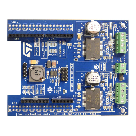
Figure 2. STEVAL-DPSG474 adapter board
UM2997
UM2997 - Rev 1 page 2/24

1Features
• Control board for digital SMPS (PFC converters, HF isolating DC-DC converters, DC-AC inverters) based on
the STM32G474RE microcontroller:
–High-resolution timer (HRTIM) for D-SMPS applications
– Filter math accelerator unit (FMAC) to perform arithmetic operations on vectors
– Coprocessor (CORDIC) to provide hardware acceleration of trigonometric functions
• 64-pin DIN 41612 connector for D-SMPS modular approach
• STDC14 programming connector
• Opto-coupled serial communication for board-to-board communication
• RC filters for analog inputs
• Protection of the microcontroller analog lines with diode arrays
• ESD protection on SWD and COM lines
• Adapter board provided for programming and user communication (USART, CAN, SMBus)
• Supply voltage: 5 V
• Embedded 5 V/3.3 V voltage regulator
• Dedicated test points for debugging
• LED signaling for power-on, faults, errors, and general purpose
• RoHS compliant
UM2997
Features
UM2997 - Rev 1 page 3/24

2Overview
The STEVAL-DPSG474 has been specifically designed to control digital-based power converters (DSMPS) such
as PFC converters, resonant converters, and HF isolating DC-DC converters in general. It interfaces with the
power board using a standard 64-pin DIN 41612 connector, which provides control signals, ADC channels, COMP
I/O, GPIOs, and the communication features needed to implement advanced control techniques for a wide range
of DSMPS applications.
The control board embeds an STM32G474RE microcontroller with a high-resolution timer (HRTIM), which
guarantees a fine control capability, specially for high frequency and resonant converters.
Figure 3. STEVAL-DPSG474 control board: main components
1. U1: STM32G474RE 32-bit microcontroller
2. U2: DSMPS standard 64-pin connector for digital power applications
3. U3: STDC14 connector to program and/or debug applications via ST-LINKV3 or to connect the adapter board
4. U4: Supply connector to provide an external 5 V
5. U5: LDO to regulate a 3.3 V to supply MCU
6. U6-U7: UART iso-connectors to connect another control board
7. U8: Test points to debug the user application
1
2
3
45
67
8
Figure 4. STEVAL-DPSG474 adapter board: main components
1. U1: JTAG connector
2. U2: jumpers to configure the user communication
3. U3: STDC14 connector to program and/or connect the adapter board
4. U4: RS-232 connector
5. U5: CAN connector
6. U6: reset button
12
3
4
56
UM2997
Overview
UM2997 - Rev 1 page 4/24

2.1 DSMPS connector
The DSMPS connector is a 64-pin ST standard connector adopted in several power conversion evaluation kits
(for example, STEVAL-DPSLLCK1, STEVAL-DPSTPFC1, STEVAL-LLL009V1, etc.), which allows an easy control
board connection and a fast microcontroller change. Thanks to this modular approach, you can use the same
control board for different applications, or change the microcontroller to evaluate the performances of the latest
ST products.
Table 1. DSMPS connector V 1.7 pinout and related MCU AF
DSMPS connector function DIN 41612 pin MCU pin STM32G474RE alternate function
VDD_iso A1 - -
GND_iso B1 - -
UART_TX_iso A2 PB6 USART1_TX
UART_RX_iso B2 PB7 USART1_RX
N.C. A3 - -
N.C. B3 - -
CAN_1_TX/SPI_NSS A4 PA15 SPI1_NSS/SPI3_NSS/FDCAN3_TX
CAN_1_RX/SPI_SCK B4 PB3 SPI1_SCK/FDCAN3_RX
SMBus_SCL/UI_USART_RX/CAN_2_RX A5 PB8-BOOT0 FDCAN1_RX/I2C1_SCL/USART3_RX
SMBus_SMBA/SPI_MOSI/EEV_4 B5 PB5 I2C1_SMBA/SPI1_MOSI/HRTIM_EEV6
SMBus_SDA/UI_USART_TX/CAN_2_TX A6 PB9 FDCAN1_TX/I2C1_SDA/USART3_TX
GND B6 VSS -
+5V A7 - -
+3.3V B7 VDD, VBAT -
FAULT_1 A8 PC10 HRTIM_FLT6
GPIO_1/GP_PWM_1 B8 PC13 GPIO/TIM1_CH1N
PWM_1 A9 PA8 HRTIM_CHA1/TIM1_CH1
PWM_2 B9 PA9 HRTIM_CHA2/TIM1_CH2
PWM_3 A10 PA10 HRTIM_CHB1/TIM1_CH3
PWM_4 B10 PA11 HRTIM_CHB2/TIM1_CH4/TIM1_CH1N
PWM_5 A11 PB12 HRTIM_CHC1
PWM_6 B11 PB13 HRTIM_CHC2/TIM1_CH1N
PWM_7 A12 PB14 HRTIM_CHD1/TIM15_CH1/TIM1_CH2N
PWM_8 B12 PB15 HRTIM_CHD2/TIM15_CH2/TIM15_CH1N/
TIM1_CH3N
PWM_9 A13 PC8 HRTIM_CHE1/TIM3_CH3/TIM8_CH3
PWM_10 B13 PC9 HRTIM_CHE2/TIM3_CH4/TIM8_CH4
PWM_11 A14 PC6 HRTIM_CHF1/TIM8_CH1/TIM3_CH1
PWM_12 B14 PC7 HRTIM_CHF2/TIM8_CH2/TIM3_CH2
GPIO_2/COMP_2_OUT/GP_PWM_2 A15 PB1 COMP4_OUT/TIM3_CH4
GPIO_3/COMP_1_OUT/FAULT_2 B15 PA12 HRTIM_FLT1/COMP2_OUT
GPIO_4/EEV_1 A16 PC12 HRTIM_EEV1
GND B16 VSS -
GPIO_5/DAC_1 A17 PA4 DAC1_OUT1
GPIO_6/DAC_2 B17 PA5 DAC1_OUT2
UM2997
DSMPS connector
UM2997 - Rev 1 page 5/24

DSMPS connector function DIN 41612 pin MCU pin STM32G474RE alternate function
GPIO_7/DAC_3/OP-AMP_1_OUT A18 PA6 DAC2_OUT1/OPAMP2_VOUT
GPIO_8/EEV_2 B18 PC11 HRTIM_EEV2
GPIO_9/EEV_3/SPI_MISO A19 PB4 HRTIM_EEV7/SPI1_MISO
GPIO_10 B19 PC14 -
ADC_1/DIFF_ADC_1+ A20 PA0 ADC12_IN1/COMP1_INM/COMP3_INP
A_VDD B20 VDDA -
ADC_2/DIFF_ADC_1-/OP-AMP_2+ A21 PA1 ADC12_IN2/OPAMP1-3_VINP
A_GND B21-B32 VSSA -
ADC_3/DIFF_ADC_2+/OP-AMP_2_OUT/
COMP_1_INM A22 PA2 ADC1_IN3/COMP2_INM/OPAMP1_VOUT
ADC_4/DIFF_ADC_2-/OP-AMP_2- A23 PA3 ADC1_IN4/OPAMP1_VINM
ADC_5 A24 PC4 ADC2_IN5
ADC_6/OP-AMP_1- A25 PC5 ADC2_IN11/OPAMP2_VINM/OPAMP1_VINM
COMP_2_INP/ADC_12/OP-AMP_1+ A26 PB0 COMP4_INP/ADC3_IN12/ADC1_IN15/
OPAMP2-3_VINP
ADC_7/COMP_2_INM A27 PB2 ADC2_IN12/COMP4_INM/COMP3_INP
ADC_8/COMP_4_INM A28 PC0 ADC12_IN6/COMP3_INM
ADC_9/COMP_4_INP A29 PC1 ADC12_IN7/COMP3_INP
ADC_10/COMP_4_OUT A30 PC2 ADC12_IN8/COMP3_OUT
COMP_1_INP/ADC_11 A31 PA7 COMP2_INP/ADC2_IN4
COMP_3_INP A32 PB11 COMP6_INP
2.2 STDC14 connector
The CN1 connector can be used either to connect a standard ST-LINKV3 dongle, which allows programming
the microcontroller and debugging the user application using an SWD connection. It also allows connecting the
adapter board included in the STEVAL-DPSG474 kit.
Table 2. CN1 connector pinout
STD14 pin number Function
1 N.C.
2 N.C.
3 3.3V
4 SWDIO
5 GND
6 SWCLK
7 GND
8 N.C.
9 N.C.
10 I2C1_SMBA
11 GND
12 NRST
13 FDCAN1_RX/I2C1_SCL/USART3_RX
14 FDCAN1_TX/I2C1_SDA/USART3_TX
UM2997
STDC14 connector
UM2997 - Rev 1 page 6/24

2.3 Adapter board
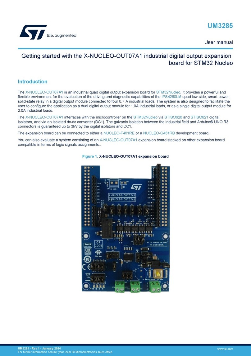
The adapter board allows extending the communication interfaces or using a standard 20-pin JTAG dongle to
program the MCU or debug the user application.
You can configure the MCU communication interface (USART3) in UART, CAN, or SMBUS according to the
jumper configuration (J9 and J11). An on-board RS-232 and a CAN transceiver provides the corresponding
outputs on P1 (DB9 female) and P2 (DB9 male) connectors, respectively.
The SMBUS connection is available on the J2 connector. A reset button is also present on the board.
Table 3. Adapter jumper configurations
Function Configuration
UART
CAN
SMBUS
2.4 Isolated serial communication
The control board also features an isolated bidirectional UART communication, which is connected to the MCU
USART1 peripheral.
Tx and Rx signals passes through a digital optocoupler (U8), before being available on the DSMPS connector and
the J3 connector.
The digital optocoupler needs to be supplied on the secondary side by using the VDD_iso and GND_iso pins
on the main 64-pin connector. You can also directly connect two control boards, referred to two isolated supply
voltages, by connecting the J3 connector of the first board to the J4 connector of the second board (or vice versa)
using the provided flat cable. Thus, the VDD supply voltage of the second board becomes the isolated supply
voltage (VDD_iso) to supply the digital optocoupler of the first one.
2.5 LEDs
The control board embeds three user LEDs that, in ST FW applications, are usually adopted to show the status of
the power converter and if any fault occurred. The number of blinks of each LED depends on the final application.
Table 4. Control board LEDs
Diode Name Color Function
D2 STATUS_LED Blue Status LED: it indicates whether the converter is working normally (LED on), or it is in startup
state.
UM2997
Adapter board
UM2997 - Rev 1 page 7/24

Diode Name Color Function
D3 FAULT_LED Red Fault LED: it indicates that a nonrecoverable fault occurred (for example, an overcurrent, etc.)
and you have to restart the board.
D4 ERROR_LED Yellow Error LED: it indicates that a recoverable fault occurred (for example, an input undervoltage,
etc.). The board restarts normal operation when the error is cleared.
UM2997
LEDs
UM2997 - Rev 1 page 8/24

3Getting started
3.1 System requirements
• Windows® OS (7, 8, or 10), Linux® 64-bit, or macOS®
•Debugger and programmer for STM32 (ST-LINKV3, ST-LINK/V2) with the related cable
Note: macOS® is a trademark of Apple Inc. registered in the U.S. and other countries.
Linux® is a registered trademark of Linus Torvalds.
All other trademarks are the property of their respective owners.
3.2 Development toolchains
• IAR Systems - IAR Embedded Workbench®
•Keil® - MDK-ARM
Note: IAR Embedded Workbench® and MDK-ARM are available on Windows® only.
• STMicroelectronics - STM32CubeIDE
3.3 How to use the kit
3.3.1 Standalone mode
To use the STEVAL-DPSG474 standalone, execute the following procedure.
Step 1. Choose one of the substeps below.
Step 1a. Connect the ST-LINKV3 programmer to the STD14 (CN1) connector and connect the USB
cable to the PC.
Step 1b. Connect the adapter board to the STD14 (CN1) connector to use a programmer with a
standard 20-pin JTAG connector, or to use one of the provided communication interfaces
(UART, CAN, or SMBUS).
Step 2. Provide an external 5 V supply voltage to the J1 connector.
The green LED (D1) turns on.
3.3.2 Using another power board
To use the STEVAL-DPSG474 with another evaluation power board, follow the related user manual.
Important: Adopt an isolated programmer or a digital isolator to debug the power application running.
UM2997
Getting started
UM2997 - Rev 1 page 9/24

4Schematic diagrams
Figure 5. STEVAL-DPSG474 control board: MCU circuit schematic
PWM SIGNALS
COMMUNICATION
GPIO AND ALTERNATE FUNCTIONS
LEDs
VOLTAGE REGULATOR
ANALOG INPUTS
GND CON
Stripline male 2x1 2.54mm
To place capacitors as close as possible to each Vdd Pin
MCU I/O
SUPPLY VOLTAGES
SWD & USER COMMUNICATION CONNECTORS
DSMPS CONNECTOR PINS
MCU VDD
ESD PROTECTIONS
CAN_1_TX/SPI_NSS
SMBus_SCL/UI_USART_RX/CAN_2_RX
+5V
+3.3V
FAULT_1
SMBus_SDA/UI_USART_TX/CAN_2_TX
PWM_1
PWM_2
PWM_3
PWM_4
PWM_5
PWM_6
PWM_7
PWM_8
PWM_9
GPIO_2/COMP_2_OUT/GP_PWM_2
GPIO_4/EEV_1
GPIO_5/DAC_1
GPIO_6/DAC_2
GPIO_7/DAC_3/OP-AMP_1_OUT
GPIO_8/EEV_2
GPIO_10
GPIO_9/EEV_3/SPI_MISO
A_VDD
ADC_1/DIFF_ADC_1+
ADC_2/DIFF_ADC_1-/OP-AMP_2+
ADC_5
ADC_3/DIFF_ADC_2+/OP-AMP_2_OUT/COMP_1_NM
ADC_4/DIFF_ADC_2-/OP-AMP_2-
ADC_6/OP-AMP_1-
COMP_2_INP/ADC_12/OP-AMP_1+
ADC_7/COMP_2_INM
ADC_8/COMP_4_INM
ADC_9/COMP_4_INP
ADC_10/COMP_4_OUT
PWM_10
COMP_1_INP/ADC_11
PWM_11
PWM_12
CAN_1_RX/SPI_SCK
SMBus_SMBA/SPI_MOSI/EEV_4
MCU_USART_ISO_TX
MCU_USART_ISO_RX
GPIO_1/GP_PWM_1
GND
COMP_3_INP
GPIO_3/COMP_1_OUT/FAULT_2
GND
GND
GND
GND
+5V
GNDGND
VDDA
+3.3V
GND GND
GND A_GND
A_GND
+3.3V
+5V
+3.3V
VDDA
A_GND
VDDA
A_GND
A_GND
VDDA
A_GND
A_GND
VDDA
A_GND
A_GND
VDDA
A_GND
GND
A_GND
GND
VDDA
VDDA
GND
GND
GND
GND
GND
+3.3V
GND
GND
A_GND
+3.3V
+3.3V
GND
GND
GND
GND GND
GND
U4
5
DA108S1RL
8
REF4
1
REF1 2
I/O 1
3
I/O 2
4
I/O 3
6
I/O 4
7
REF3
REF2
TP2
L1
1 2
470 OHM
TP46
R11
270
TP29
Y1
2
24MHz
43
TP34
TP25
TP28
R18
10R
TP42
C16
1uF
12
C12
1
10pF
2
C37
1
0.1uF
2
R24
10R
U6 2
LD1117S33CTR
Vout_2
1
GND
3Vin 4
Vout_4
C8
10pF
12
C27
10pF
12
TP5
C24
1
0.1uF
2
2 of 2
U2A
15
VSS1
STM32G474RET6
27
VSSA
28
1
VREF+
VBAT 29
VDDA
31
VSS2
16 VDD1
32 VDD2
48 VDD3 47
VSS3 63
VSS4
64 VDD4
U5
5
DA108S1RL
REF4
8REF1 1
2
I/O 1
3
I/O 2
4
I/O 3
6
I/O 4
7
REF3
REF2
TP12
R28
10R
R13
10R
D2
A C
LED BLUE
TP40
TP21
U7
1
2
3
TP15
R17
10R
TP17
TP45
R14
270
C35
1
470nF
2
TP43
TP33
TP19
D5
R22
SMAJ5.0A-TR
10R
TP1
C30
10uF
12
C34
10nF
12
TP11
C15
1
0.1uF
2
TP32
TP24
TP27
TP39
C6
1
10pF
2
TP4
C9
1
6.8pF
12
C20
1
0.1uF
2
R12
10R TP6
C28
1
10pF
2
U3
5
DA108S1RL
8
REF4
1
REF1 2
I/O 1
3
I/O 2
4
I/O 3
6
I/O 4
REF3
7REF2
R16
10k
J7
Con2
1 2
C10
1
6.8pF
2
TP37
+
C31
12
100uF16V
C13
10pF
12
TP10
TP14
R25
10R
TP8
D1
A C
LED GREEN
TP38
TP26
D4
A C
LED YELLOW
C18
1
0.1uF
2
TP41
TP18
C19
1
470nF
2
C32
1
0.1uF
2
C23
1
0.1uF
2
TP36
R10
10R
CN1
1 2
3 4
5 6
ST-LInk V3 & Adapter CON
7 8
9 10
11 12
13 14
R8
270
TP31
TP23
C25
1
10pF
2
0
R21
TP20
R32
47k
R20
10R
TP3
TP9
C7
1
10pF
2
TP30
R23
10R
J1
1
2
Ext Supply
D3
A
RED LED
C
R9
10R
C5
10pF
12
C29
10pF
12
C14
1
10pF
2
J5
TP44
Jumper-Female
TP13
R26
47k
R15
270
0
R29
C22
1
0.1uF
2
C26
10pF
12
TP7
C11
1
10pF
2
C21
1
0.1uF
2
J6
1
2
C36
Con2_Strp_male_SMD
1
0.1uF
2
0
R30
R19
10R
1 of 2
U2B
12 PA0
STM32G474RET6
13 PA1
14 PA2
17 PA3
18 PA4
19 PA5
0PA6
21 PA7
42 PA8
DAC2_OUT1/OPAMP2_VOUT
2
43 PA9
44 PA10
45 PA11
46 PA12
49 PA13
50 PA14
51 PA15
24 PB0
25 PB1
26 PB2
56 PB3
57 PB4
58 PB5
59 PB6
60 PB7
61
62 PB8-BOOT0
PB9
30 PB10
33 PB11
34 PB12
35 PB13
36 PB14
37 PB15
8
PC0 9
PC1 10
PC2 11
PC3 22
PC4 23
PC5 38
PC6 39
PC7 40
PC8 41
PC9 52
PC10 53
PC11 54
2
PC12
3
PC13
4
PC14-OSC32_IN
55
PD2
5
PC15-OSC32_OUT
6
PF0-OSC_IN
7
PF1-OSC_OUT
PG10-NRST
C17
1
0.1uF
2
TP35
C33
10uF
12
TP22
IC1
1I_O1
ESDALC6V1W5
2GND
3I_O2 4
I_O3
5
I_O4
TP16
SPI1_NSS/FDCAN3_TX
FDCAN1_RX/I2C1_SCL/USART3_RX
HRTIM_FLT6
FDCAN1_TX/I2C1_SDA/USART3_TX
HRTIM_CHA1/TIM1_CH1
HRTIM_CHA2/TIM1_CH2
HRTIM_CHB1/TIM1_CH3
HRTIM_CHC1
HRTIM_CHB2/TIM1_CH4
HRTIM_CHC2/TIM1_CH1N
HRTIM_CHD1/TIM1_CH2N
HRTIM_CHD2/TIM1_CH3N
HRTIM_CHE1/TIM8_CH3
COMP4_OUT/TIM3_CH4
HRTIM_EEV1
DAC1_OUT1
DAC1_OUT2
HRTIM_EEV2
DAC2_OUT1/OPAMP2_VOUT
PC14
HRTIM_EEV7/SPI1_MISO
HRTIM_CHE2/TIM8_CH4
HRTIM_CHF1/TIM8_CH1
HRTIM_CHF2/TIM8_CH2
SPI1_SCK/FDCAN3_RX
TIM1_CH1N
I2C1_SMBA/SPI1_MOSI/HRTIM_EEV6
USART1_RX
COMP2_OUT/HRTIM_FLT1
USART1_TX
STATUS_LED
FAULT_LED
ERROR_LED
ADC12_IN1
ADC12_IN2/OPAMP1_VINP
ADC1_IN3/OPAMP1_VOUT/COMP2_INM
ADC1_IN4/OPAMP1_VINM
ADC2_IN5
ADC2_IN11/OPAMP2_VINM
ADC12_IN6/COMP3_INM
ADC12_IN7/COMP3_INP
COMP6_INP
ADC12_IN1
ADC12_IN2/OPAMP1_VINP
ADC1_IN3/OPAMP1_VOUT/COMP2_INM
DAC1_OUT1
ADC1_IN4/OPAMP1_VINM
DAC1_OUT2
COMP2_INP/ADC2_IN4
HRTIM_CHA1/TIM1_CH1
HRTIM_CHA2/TIM1_CH2
HRTIM_CHB1/TIM1_CH3
HRTIM_CHC1
HRTIM_CHB2/TIM1_CH4
HRTIM_CHC2/TIM1_CH1N
HRTIM_CHD1/TIM1_CH2N
HRTIM_CHD2/TIM1_CH3N
HRTIM_CHE1/TIM8_CH3
HRTIM_CHE2/TIM8_CH4
HRTIM_CHF1/TIM8_CH1
HRTIM_CHF2/TIM8_CH2
HRTIM_FLT6
SPI1_NSS/FDCAN3_TX
SPI1_SCK/FDCAN3_RX
FDCAN1_RX/I2C1_SCL/USART3_RX
FDCAN1_TX/I2C1_SDA/USART3_TX
USART1_TX
USART1_RX
I2C1_SMBA/SPI1_MOSI/HRTIM_EEV6
TIM1_CH1N
COMP4_OUT/TIM3_CH4
HRTIM_EEV1COMP2_OUT/HRTIM_FLT1
HRTIM_EEV2
PC14
ADC2_IN5
HRTIM_EEV7/SPI1_MISO
ADC2_IN11/OPAMP2_VINM
COMP4_INP/ADC3_IN12/OPAMP2_VINP
ADC2_IN12/COMP4_INM
ADC12_IN6/COMP3_INM
ADC12_IN7/COMP3_INP
COMP6_INP
ADC12_IN8/COMP3_OUT
STATUS_LED
FAULT_LED
ERROR_LED
DEBUG_PIN
DEBUG_PIN
NRST
SWCLK
SWDIO
NRST
FDCAN1_RX/I2C1_SCL/USART3_RX
SWDIO
SWCLK
FDCAN1_TX/I2C1_SDA/USART3_TX
SWDIO
SWCLK
FDCAN1_RX/I2C1_SCL/USART3_RX
NRST
FDCAN1_TX/I2C1_SDA/USART3_TX
I2C1_SMBA/SPI1_MOSI/HRTIM_EEV6
COMP4_INP/ADC3_IN12/OPAMP2_VINP
ADC2_IN12/COMP4_INM
ADC12_IN8/COMP3_OUT
COMP2_INP/ADC2_IN4
UM2997 - Rev 1 page 10/24
UM2997
Schematic diagrams

Figure 6. STEVAL-DPSG474 control board: D-SMPS connector circuit schematic
VDD_iso
USART_TX_iso USART_RX_iso
CAN_1_TX/SPI_NSS CAN_1_RX/SPI_SCK
SMBus_SCL/UI_USART_RX/CAN_2_RX SMBus_SMBA/SPI_MOSI/EEV_4
SMBus_SDA/UI_USART_TX/CAN_2_TX
+5V +3.3V
FAULT_1 GPIO_1/GP_PWM_1
PWM_1 PWM_2
PWM_3 PWM_4
PWM_5 PWM_6
PWM_7 PWM_8
PWM_9 PWM_10
PWM_11 PWM_12
GPIO_2/COMP_2_OUT/GP_PWM_2 GPIO_3/COMP_1_OUT/FAULT_2
GPIO_4/EEV_1
GPIO_5/DAC_1 GPIO_6/DAC_2
GPIO_7/DAC_3/OP-AMP_1_OUT GPIO_8/EEV_2
GPIO_9/EEV_3/SPI_MISO GPIO_10
ADC_1/DIFF_ADC_1+ A_VDD
ADC_2/DIFF_ADC_1-/OP-AMP_2+
ADC_3/DIFF_ADC_2+/OP-AMP_2_OUT/COMP_1_NM
ADC_4/DIFF_ADC_2-/OP-AMP_2-
ADC_5
ADC_6/OP-AMP_1-
COMP_2_INP/ADC_12/OP-AMP_1+
ADC_7/COMP_2_INM
ADC_8/COMP_4_INM
ADC_9/COMP_4_INP
ADC_10/COMP_4_OUT
COMP_1_INP/ADC_11
COMP_3_INP
GND_iso
GND
GND
A_GND
P1
Digital Power Connector
A1
A2
A3
A4
A5
A6
A7
A8
A9
A10
A11
A12
A13
A14
A15
A16
A17
A18
A19
A20
A21
A22
A23
A24
A25
A26
A27
A28
A29
A30
A31
A32
B1
B2
B3
B4
B5
B6
B7
B8
B9
B10
B11
B12
B13
B14
B15
B16
B17
B18
B19
B20
B21
B22
B23
B24
B25
B26
B27
B28
B29
B30
B31
B32
UM2997 - Rev 1 page 11/24
UM2997
Schematic diagrams

Figure 7. STEVAL-DPSG474 control board: isolated communication circuit schematic
VDD_iso
MCU_USART_ISO_TX
USART_TX_iso
USART_RX_iso
MCU_USART_ISO_RX
VDD_iso
VDD_iso
GND_iso GND
+3.3V
GND
GND_iso
+3.3V
GND_iso
VDD_iso
GND
GND GND_iso
J3
COM ISO
1
2
3
4
J4
COM
1
2
3
4
R31
47R
R5 39
C3
15pF
1 2
C2
0.1uF
1 2
C1
0.1uF
1 2
R3 39
R4
0
R1
47R
ACSL-6210
U8
Vout2 6
GND2/K1 5
A1 8
GND1/K2
1
Vout1
2
VDD1
3
A2
4
VDD2 7
C4
15pF
1 2
R2
0
MCU_USART_ISO_RX
USART_TX_iso
USART_RX_iso
MCU_USART_ISO_TX
MCU_USART_ISO_TX
USART_TX_iso
USART_RX_iso
MCU_USART_ISO_RX
UART OPTOCOUPLER
CONNECTION BETWEEN TWO CONTROL BOARDS
TO PLACE ON THE RIGHT AND ON THE LEFT SIDE OF THE BOARD, RESPECTIVELY
UM2997 - Rev 1 page 12/24
UM2997
Schematic diagrams

Figure 8. STEVAL-DPSG474 adapter board circuit schematic
Male Connector 2x10
Pitch 2.54 mm
Tyco Electronics 2 -1634688-0
RS: 473-8282
Farnell: 8395942
TD
RD
CAN COMMUNICATION
RS: 461- 9771
GND
GND
+3.3V
+3.3V +3.3V
GND
GND
GND
GND
GND
+3.3V
GND GND
GND
+3.3V
GND+3.3V GND
+3.3V
GND
+3.3V
+3.3V
GND
U1
ST3232EBTR
C1P
1
VP
2
C1M
3
C2P
4
C2M
5
VM
6
T2OUT
7
R2IN
8R2OUT 9
T2IN 10
T1IN 11
R1OUT 12
R1IN 13
T1OUT 14
GND 15
VCC 16
J6
JP_JTDI
1 2
C7
0.1uF
12
C5
0.1uF
12
R2
4.7k
C2
0.1uF
12
R6
0
N.M.
P2
DB9-male connector
5
9
4
8
3
7
2
6
1
M1 M2
C4
0.1uF
12
J7
1 2
R4
120R
J15
Jumper_Female
J11
1
3
2
J13
Jumper_Female
J9
1
3
2
J14
Jumper_Female
R3
10k
J2
con6-2x3-strip-male
1 2
3 4
5 6
C3 0.1uF
1 2
J12
CON20-JTAG
1 2
3 4
5 6
7 8
9 10
11 12
13 14
15 16
17 18
19 20
J8
2 1
R14
270
J16
Jumper_Female
C8
0.1uF
12
S1
RST
1
4
2
3
C6
0.1uF
12
D1
RED LED
AC
C1
0.1uF
1 2
1 2
3 4
5 6
7 8
9 10
11 12
13 14
R5
0
U2
SN65HVD232D
D
1
GND
2
VCC
3
R
4NC1 5
NC 8
CANL 6
CANH 7
P1
DB9-Female
5
9
4
8
3
7
2
6
1
R1
4.7k
JTDI_JTAG_ADP
JTMS_ADP
JTCK_ADP
JTDO_ADP
RESET#_BTN RESET#_ADP
RESET#_BTN
CAN_TX
CAN_RX
SMBUS_SCL I2C_SMBA
SMBUS_SDA
USART_TX
I2C_SDA/USART_TX/CAN_TX
CAN_TX
USART_RX
SMBUS_SCL
I2C_SCL/USART_RX/CAN_RX
CAN_RX
SMBUS_SDA
JTMS_ADP
JTCK_ADP
I2C_SMBA
RESET#_ADP
I2C_SDA/USART_TX/CAN_TXI2C_SCL/USART_RX/CAN_RX
USART_TX
USART_RX
JTAG
CAN
SWD USER-COMMUNICATION
SMBUS
USER COMMUNICATION CONFIG
RESET BUTTON RS-232 SERIAL COMMUNICATION
CN1
ST-LInk V3 & Adapter CON
place reset button in the external part of the board
default setting: jumper mounted
UM2997 - Rev 1 page 13/24
UM2997
Schematic diagrams

5Bill of materials
Table 5. STEVAL-DPSG474 bill of materials
Item Q.ty Ref. Part/value Description Manufacturer Order code
1 1 Table 6. STEVAL-DPSG474M - Control board ST Not available for separate sale
2 1 Table 7. STEVAL-DPSADP02 - Adapter board ST Not available for separate sale
Table 6. Control board bill of materials
Item Q.ty Ref. Part/value Description Manufacturer Order code
1 13
C1 C2 C15
C17 C18
C20 C21
C22 C23
C24 C32
C36 C37
0.1uF 0603 (1608 Metric) 50V
±10%
CAP CER 0.1UF 50V
X7R 0603
Wurth Electronics
Inc. 885012206095
2 2 C3 C4 15pF 0603 (1608 Metric) 50V
±5%
CAP CER 15pF 50V
COG 0603
Wurth Electronics
Inc. 885012006052
3 13
C5 C6 C7 C8
C11 C12
C13 C14
C25 C26
C27 C28
C29
10pF 0603 (1608 Metric) 50
±5%
CAPACITOR
CERAMIC SMD 0603
Wurth Elektronik
Inc. 885012006051
4 2 C9 C10 6.8pF 0603 (1608 Metric) 50V
0.5pF
CAP CER 6.8PF 50V
C0G/NP0 0603
Wurth Electronics
Inc. 885012006050
5 1 C16 1uF 0603 (1608 Metric) 25V
±10%
CAP CER 1UF 25V
X7R 0603
Wurth Electronics
Inc. 885012206076
6 2 C19 C35 470nF 0603 (1608 Metric) 25V
±10%
CAP CER 0.47UF
25V X7R 0603
Wurth Electronics
Inc. 885012206075
7 2 C30 C33 10uF 0805 (2012 Metric) 16V
±20%
CAP CER 10UF 16V
X5R 0805
Wurth Electronics
Inc. 885012107014
8 1 C31 100uF Radial, Can - SMD 16V
±20%
CAP ALUM 100UF
20% 16V SMD
Panasonic
Electronic
Components
EEE-FT1C101AR
9 1 C34 10nF 0603 (1608 Metric) 50V
±10%
Ceramic Multilayer
Capacitors X7R
Wurth Elektronik
Inc. 885012206089
10 1 CN1 ST-LInk V3 & Adapter CON CONN HEADER
SMD 14POS 1.27MM Samtec Inc. FTSH-107-01-F-DV-
K-P-TR
11 1 D1 LED GREEN 0603 (1608
Metric) 20mA
LED GREEN CLEAR
0603 SMD Würth Elektronik 150060GS75000
12 1 D2 LED BLUE 0603 (1608 Metric)
20mA
LED BLUE 0603
SMD
Vishay
Semiconductor
Opto Division
VLMB1310-GS08
13 1 D3 RED LED 0603 (1608 Metric)
20mA
LED RED CLEAR
0603 SMD
Wurth Electronics
Inc. 150060RS75000
14 1 D4 LED YELLOW 0603 (1608
Metric) 20mA
LED YELLOW
CLEAR 0603 SMD
Wurth Electronics
Inc. 150060YS75000
15 1 D5 SMAJ5.0A-TR, SMA F2 400 W TVS in SMA ST SMAJ5.0A-TR
16 1 IC1 ESDALC6V1W5, SOT323-5L Quad Transil array for
ESD protection ST ESDALC6V1W5
17 1 J1 Ext Supply CONN TERM BLOCK
2.54MM 2POS Phoenix Contact 1725656
UM2997
Bill of materials
UM2997 - Rev 1 page 14/24

Item Q.ty Ref. Part/value Description Manufacturer Order code
18 1 J3 COM ISO
CONN FMALE-ON-
BRD 4POS VERT
T/H
TE Connectivity
AMP Connectors 215079-4
19 1 J4 COM
CONN FMALE-ON-
BRD 4POS VERT
T/H
TE Connectivity
AMP Connectors 215079-4
20 1 J5 Jumper-Female
CONN JUMPER
SHORTING 1.27MM
GOLD
Sullins Connector
Solutions NPB02SVAN-RC
21 1 J6 Con2_Strp_male_SMD CONN HEADER
SMD 2POS 1.27MM Harwin Inc. M50-3630242R
22 1 J7 Con2 CONN HEADER
2POS VERT T/H Amphenol FCI 77311-118-02LF
23 1 L1 470 OHM 0402 (1005 Metric) FERRITE BEAD 470
OHM 0402 1LN
Wurth Electronics
Inc. 7427927141
24 1 P1 Digital Power Connector Connector Erni 90°
384241 32X2 male ERNI 384241
25 2 R1 R31 47R 0603 (1608 Metric) 0.1W,
1/10W ±1%
CHIP RESISTOR
SMD 1% 1/10W 0603 Yageo RC0603FR-0747RL
26 4 R2 R4 R21
R30
0 0603 (1608 Metric) 0.1W,
1/10W ±1%
CHIP RESISTOR
SMD 1% 1/10W 0603 Yageo RC0603FR-070RL
27 2 R3 R5 39 0603 (1608 Metric) 0.1W,
1/10W ±1%
RES SMD 39 OHM
1% 1/10W 0603
Panasonic
Electronic
Components
ERJ-3EKF39R0V
28 4 R8 R11 R14
R15
270 0603 (1608 Metric) 0.1W,
1/10W ±1%
CHIP RESISTOR
SMD 1% 1/10W 0603 TE Connectivity CRGP0603F270R
29 13
R9 R10 R12
R13 R17
R18 R19
R20 R22
R23 R24
R25 R28
10R 0603 (1608 Metric) 0.1W,
1/10W ±1%
CHIP RESISTOR
SMD 1% 1/10W 0603
Stackpole
Electronics RMCF0603FT10R0
30 1 R16 10k 0603 (1608 Metric) 0.1W,
1/10W ±1%
RES SMD 10K OHM
1% 1/10W 0603 Yageo RC0603FR-0710KL
31 2 R26 R32 47k 0603 (1608 Metric) 0.1W,
1/10W ±1%
RES SMD 47K OHM
1% 1/10W 0603 Yageo RC0603FR-0747KL
32 1 R29 0 1206 (3216 Metric) 0.25W,
1/4W ±1%
CHIP RESISTOR
SMD 1% 1/4W 1206 Yageo RC1206JR-070RL
33 46
TP1 TP2
TP3 TP4
TP5 TP6
TP7 TP8
TP9 TP10
TP11 TP12
TP13 TP14
TP15 TP16
TP17 TP18
TP19 TP20
TP21 TP22
TP23 TP24
TP25 TP26
TP27 TP28
TP29 TP30
TP31 TP32
TP33 TP34
TP35 TP36
TP37 TP38
TP39 TP40
5001 0.100" Dia x 0.180" L
(2.54mm x 4.57mm)
TEST POINT PC
MINI .040"D BLACK
Keystone
Electronics 5001
UM2997
Bill of materials
UM2997 - Rev 1 page 15/24

Item Q.ty Ref. Part/value Description Manufacturer Order code
TP41 TP42
TP43 TP44
TP45 TP46
34 1 U2 STM32G474RET6, LQFP 64
10x10x1.4 mm
Arm® Cortex®-M4
32b MCU+FPU,
512KB Flash, 150
MHz, 128KB SRAM
ST STM32G474RET6
35 3 U3 U4 U5 DA108S1RL, SO-8 Diode array of 8
diodes ST DA108S1RL
36 1 U6 LD1117S33CTR, SOT-223
Adjustable and fixed
low drop positive
voltage regulator
ST LD1117S33CTR
37 1 U7 BAR43SFILM, SOT23
30 V, 100 mA Vf
0.33 V @ 2 mA
SMD general purpose
signal Schottky diode
ST BAR43SFILM
38 1 U8 ACSL-6210 8-SOIC (0.154",
3.90mm Width)
OPTOISO 2.5KV
2CH OPEN COLL
8SO
Broadcom Limited ACSL-6210-50RE
39 1 Y1 24MHz 4-SMD, No Lead,
(3.20 x 2.50mm)
CRYSTAL 24.00 MHZ
9.0PF SMD EPSON TSX-3225
24.0000MF15X-AC6
40 1
Micro-Match
4 ways,
9.9"",
250mm,
1.27mm
Cable AMP Micro-Match TE Connectivity 1483350-3
Table 7. Adapter board bill of materials
Item Q.ty Ref. Part/value Description Manufacturer Order code
1 8
C1 C2
C3 C4
C5 C6
C7 C8
0.1uF 50 V ±10% 0603
(1608 Metric)
CAP CER 0.1UF 50V X7R
0603
Wurth Electronics
Inc. 885012206095
2 1 CN1 ST-LInk V3 & Adapter
CON
CONN HEADER SMD
14POS 1.27MM Samtec Inc. FTSH-107-01-F-DV-K-
P-TR
3 1 D1 RED LED 0603 (1608
Metric) 20 mA
LED RED CLEAR 0603
SMD
Wurth Electronics
Inc. 150060RS75000
4 1 J2 con6-2x3-strip-male CONN HEADER .100 DUAL
STR 6POS
Sullins Connector
Solutions PEC03DFAN
5 3 J6 J7
J8 JP_JTDI Amphenol FCI 77311-118-02LF
6 2 J9 J11 JP_JTDI Amphenol FCI 77311-118-03LF
7 1 J12 CON20-JTAG CONN IDC BOX HEADER
2.54MM 20POS Tyco Electronics 2-1634688-0
8 2 J13 J14 Jumper_Female CONN JUMPER
SHORTING .100" GOLD
Sullins Connector
Solutions QPC02SXGN-RC
9 2 J15 J16 Jumper_Female CONN JUMPER
SHORTING .100" GOLD
Sullins Connector
Solutions QPC02SXGN-RC
10 1 P1 DB9-Female Wurth Electronics
Inc. 618009231321
11 1 P2 DB9-male connector CONN D-SUB PLUG 9POS
VERT SOLDER
Wurth Electronics
Inc. 618009231421
12 2 R1 R2 4.7k ±10% 0603 (1608
Metric) 0.1W, 1/10W ±1%
RES SMD 4.7K OHM 1%
1/10W 0603
Stackpole
Electronics RMCF0603FT4K70
UM2997
Bill of materials
UM2997 - Rev 1 page 16/24

Item Q.ty Ref. Part/value Description Manufacturer Order code
13 1 R3 10k 0603 (1608 Metric)
0.1W, 1/10W ±1%
RES SMD 10K OHM 1%
1/10W 0603 Yageo RC0603FR-0710KL
14 1 R4 120R 0603 (1608 Metric)
0.1W, 1/10W ±1%
RES SMD 120R OHM 1%
1/10W 0603 Yageo RC0603FR-07120RL
15 1 R5 0 0603 (1608 Metric)
0.1W, 1/10W ±1%
CHIP RESISTOR SMD 1%
1/10W 0603 Yageo RC0603FR-070RL
16 1 R6 0 0603 (1608 Metric)
0.1W, 1/10W ±1%
CHIP RESISTOR SMD 1%
1/10W 0603 (not mounted) Yageo RC0603FR-070RL
17 1 R14 270 0603 (1608 Metric)
0.1W, 1/10W ±1%
CHIP RESISTOR SMD 1%
1/10W 0603 TE Connectivity CRGP0603F270R
18 1 S1 RST SWITCH TACTILE SPST-
NO 0.05A 12V
Wurth Electronics
Inc. 430483025816
19 1 U1 ST3232EBTR,
TSSOP-16L
15 kV ESD protection, 3 to
5.5 V low power, up to 250
kbps, RS-232 drivers and
receivers
ST ST3232EBTR
20 1 U2 SN65HVD232D IC TRANSCEIVER HALF
1/1 8SOIC Texas Instruments SN65HVD232D
21 1 FLAT CABLE Samtec Inc. FFSD-07-D-06.00-01-N
UM2997
Bill of materials
UM2997 - Rev 1 page 17/24

6Kit versions
Table 8. STEVAL-DPSG474 versions
PCB version Schematic diagrams Bill of materials
STEVAL$DPSG474A (1) STEVAL$DPSG474A schematic diagrams STEVAL$DPSG474A bill of materials
1. This code identifies the STEVAL-DPSG474 evaluation kit first version. It is printed on the board PCB. The kit includes
the STEVAL-DPSG474M control board, whose first version is identified by the STEVAL$DPSG474MA code, and the
STEVAL-DPSADP02, whose first version is identified by the STEVAL$DPSADP02A code.
UM2997
Kit versions
UM2997 - Rev 1 page 18/24

7Regulatory compliance information
Formal Notice Required by the U.S. Federal Communications Commission
FCC NOTICE
This kit is designed to allow:
(1) Product developers to evaluate electronic components, circuitry, or software associated with the kit to
determine
whether to incorporate such items in a finished product and
(2) Software developers to write software applications for use with the end product.
This kit is not a finished product and when assembled may not be resold or otherwise marketed unless all
required FCC equipment authorizations are first obtained. Operation is subject to the condition that this product
not cause harmful interference to licensed radio stations and that this product accept harmful interference. Unless
the assembled kit is designed to operate under part 15, part 18 or part 95 of this chapter, the operator of the kit
must operate under the authority of an FCC license holder or must secure an experimental authorization under
part 5 of this chapter 3.1.2.
Formal Product Notice Required by Industry Canada Innovation, Science and Economic Development
Canada compliance:
For evaluation purposes only. This kit generates, uses, and can radiate radio frequency energy and has not been
tested for compliance with the limits of computing devices pursuant to Industry Canada (IC) rules.
À des fins d'évaluation uniquement. Ce kit génère, utilise et peut émettre de l'énergie radiofréquence et n'a pas
été testé pour sa conformité aux limites des appareils informatiques conformément aux règles d'Industrie Canada
(IC).
Formal product notice required by EU
This device is in conformity with the essential requirements of the Directive 2014/30/EU (EMC) and of the
Directive 2015/863/EU (RoHS).
UM2997
Regulatory compliance information
UM2997 - Rev 1 page 19/24

Revision history
Table 9. Document revision history
Date Revision Changes
12-Apr-2022 1 Initial release.
UM2997
UM2997 - Rev 1 page 20/24
Table of contents
Other ST Computer Hardware manuals

ST
ST STR9 User manual

ST
ST X-NUCLEO-OUT02A1 User manual

ST
ST STEVAL-CCH002V1 User manual

ST
ST X-NUCLEO-OUT08A1 User manual

ST
ST STEVAL-ISF001V1 User manual

ST
ST X-NUCLEO-LED61A1 User manual

ST
ST X-NUCLEO-53L1A1 User manual

ST
ST STSW-ST25DV002 User manual

ST
ST FP-SNS-FLIGHT1 User manual

ST
ST X-NUCLEO-EEPRMA2 User manual

ST
ST STM32 Nucleo User manual

ST
ST UM2960 User manual

ST
ST X-NUCLEO-OUT01A1 User manual

ST
ST X-NUCLEO-OUT02A1 User manual

ST
ST X-NUCLEO-IDW01M1 User manual

ST
ST STM32U575 Series Installation and operating instructions

ST
ST X-NUCLEO-SRC1M1 User manual

ST
ST X-NUCLEO-IKS4A1 User manual

ST
ST STM32G0 User manual

ST
ST UM2033 User manual