ST X-NUCLEO-S915A1 User manual

Getting started with the X-NUCLEO-S2915A1 Sub-1 GHz 915 MHz
RF expansion board based on S2-LP radio for STM32 Nucleo
October 2018 1/21
www.st.com
User manual
Introduction
The X-NUCLEO-S915A1 expansion board is based on the S2-LP radio and
operates in the 915 MHz ISM frequency band.
The expansion board is compatible with ST morpho and Arduino UNO R3
connectors.
The X-NUCLEO-S2915A1 interfaces with the STM32 Nucleo microcontroller
via SPI connections and GPIO pins. You can change some of the GPIOs by
mounting or removing the resistors.
The boards are equipped with the following features:
• On-board S2-LP, sub-1 GHz transceiver device
• SPI EEPROM for saving parameters
• 860 to 930 MHz RF Front-End Module(power amplifier)
• LED for user interface
• Jumper at 3V3 for checking the current consumption of the expansion
board
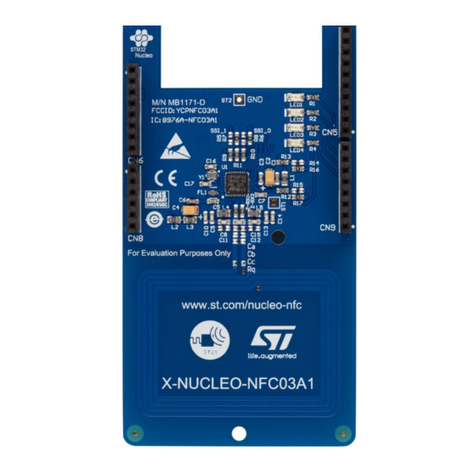
Figure 1. Sub-1 GHz expansion board based on S2-LP for STM32

User Manual
2/17 DocID-xx
Contents
1Description..................................................................................................3
1.1 Typical applications ....................................................................................... 3
1.2 Abbreviations ................................................................................................. 4
2Getting started............................................................................................5
2.1 Overview ....................................................................................................... 5
2.2 Hardware and software requirements ............................................................ 6
2.3 Board setup ................................................................................................... 7
3Hardware description and configuration..................................................8
3.1 Interconnection details ................................................................................... 8
3.2 SPI and GPIO connection options ................................................................. 9
3.3 Current measurement .................................................................................. 11
3.4 X-NUCLEO-S2915A1 component placement details ................................... 11
4Component description............................................................................12
4.1 S2-LP Radio ................................................................................................ 12
4.2 SPI EEPROM .............................................................................................. 12
5Formal Notices Required by the U.S. Federal Communications
Commission (“FCC”).................................................................................................13
6Formal Notices Required by the Industry Canada (“IC”) ......................14
7OEM Integration Instructions...................................................................16

Getting started X-NUCLEO-S2868A1
17
DocIDxx
3
/
17
1 Description
The X-NUCLEO-S2915A1 boards contain the S2-LP radio which is a high
performance ultra-low power, sub-1 GHz, RF transceiver.
Table 1. Expansion board details
Evaluation board
RF
communication
frequency
Description
X-NUCLEO-S2868A1
868 MHz
868 MHz RF expansion board based on S2-LP RF
transceiver.
X-NUCLEO-S2915A1
915 MHz
915 MHz RF expansion board based S2-LP RF
transceiver
1.1 Typical applications
The evaluation boards can be used for evaluation of the S2-LP device in
multiple applications.
The following demo examples are available for testing with the evaluation
boards
• wM-Bus: Wireless Metering Bus demo
• Point-to-point communication protocol demo
• 6LoWPAN applications
• SigFox Communication
Please refer to the data brief for the firmware, available on www.st.com.
Users can develop other applications for evaluating the devices. Some of
these applications are:
• SigFox Communication
• Automatic meter reading
• Home and building automation
• WSN (wireless sensor network)
• Industrial monitoring and control
• Wireless fire and security alarm systems

User Manual
4/17 DocID-xx
1.2 Abbreviations
Table 2. Abbreviation
Term
Meaning
AMR
Automatic meter reading
EEPROM
Electrically erasable programmable read only memory
GHz
Giga Hertz
GUI
Graphical user interface
LED
Light emitting diode
MCU
Microcontroller unit
P2P
Point-to-point communication
RF
Radio frequency communication
SPI
Serial peripheral interface
USB
Universal serial bus
wM-Bus
Wireless metering bus
WSN
Wireless sensors network
TBD
To Be Done

Getting started X-NUCLEO-S2868A1
17
DocIDxx
5
/
17
2 Getting started
This section describes the hardware requirements for the X-NUCLEO-
S2915A1 evaluation boards.
2.1 Overview
The X-NUCLEO-S2915A1 main features are:
• Based on S2-LP radio
• S2-LP narrow band ultra-low power sub-1 GHz transceiver tuned for
860 - 940 MHz frequency band
• Modulation schemes: 2-FSK, 2-GFSK05,2-GFSK1, 4-FSK, 4-GFSK05
• Air data rate from 0.1 to 500 kbps
• Ultra-low power consumption: 7 mA RX and 10 mA TX
• IEEE 802.15.4g hardware packet support with whitening, FEC, CRC
and dual SYNC word detection
• RX and TX 128 byte FIFO buffers
• Support to wireless M-Bus
• Excellent performance of receiver sensitivity (up to -130 dBm)
• Automatic acknowledgement, retransmission and timeout protocol
engine
• Compatible with STM32 Nucleo boards
• Compatible with Arduino UNO R3 connectors
• Support SMA antennas
• BALF-SPI2-01D3 IPD balun for matching network and harmonics
filter
• Sigfox compatible
• Sample firmware for P2P communication
• 6LoWPAN compatible thanks to STM32Cube
• RoHS compliant
The X-NUCLEO-S2915A1 expansion board can be used for the evaluation
of the S2-LP device in multiple applications.
The following demo samples are available for testing:
• wM-Bus demo
• Point-to-point communication protocol demo
• 6LoWPAN applications
• SigFox communication
You can develop other applications for evaluating the devices, such as:
• SigFox communication

User Manual
6/17 DocID-xx
• Automatic meter reading
• Home and building automation
• WSN
• Industrial monitoring and control
• Wireless fire and security alarm systems
2.2 Hardware and software requirements
To use STM32 Nucleo development boards with the X-NUCLEO-S2915A1
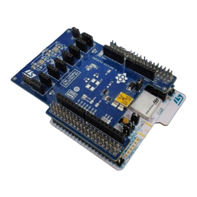
expansion board, connect the boards as shown below.
Figure 2. X-NUCLEO-S2915A1 expansion board connected to an STM32 Nucleo development board
The interconnection between the STM32 Nucleo and the X-NUCLEO-
S2915A1 has been designed to allow using any STM32 Nucleo board,
although complete testing has been performed using NUCLEO-L053R8,
NUCLEOF401RE and NUCLEO-L152RE boards hosting the ultra-low
power STM32.
The following software and hardware specifications are required:
• a PC/laptop with Microsoft Windows (7 and above) to install the
software package (X-CUBE-SUBG1)

Getting started X-NUCLEO-S2868A1
17
DocIDxx
7
/
17
• a type A USB to mini-B USB cable to connect the STM32 Nucleo
board to the PC/laptop
• 128 MB of RAM
• Approximately 40 MB of hard disk space for the firmware
• Approximately 15 MB of hard disk space for the wM-Bus GUI
The use of the wM-Bus concentrator with the GUI requires additional boards
to be connected to the PC. The GUI can be used to check the wM-Bus
communication sample.
2.3 Board setup
Perform the following steps to set up the board:
Step 1. Check that the jumper on J1 connector is connected to provide the
required voltage to the board devices.
Step 2. Connect the X-NUCLEO-S2915A1 to the STM32 Nucleo board as
shown in Figure 2. X-NUCLEOS2915A1 expansion board connected to an
STM32 Nucleo development board
Step 3. Power the Nucleo development board using the Mini-B USB cable
Step 4. Program the firmware in the STM32 on the Nucleo development
board using the firmware sample provided
Step 5. Reset the MCU board using the reset button on the Nucleo
development board
Step 6. The evaluation kit is ready-to-use

User Manual
8/17 DocID-xx
3 Hardware description and configuration
This section describes the X-NUCLEO-S2915A1 features and provides
information which could be useful to understand the board schematics.
3.1 Interconnection details
The X-NUCLEO-S2915A1 expansion board and the NUCLEO-F401RE or
NUCLEO-L152RE board connection details are listed in the table below.
Table 3. Left connector connection details
Left connector
CN6 Power
CN8 Analog
1
2
3
4
5
6
7
8
1
2
3
4
5
6
GPIO0
CSN
GPIO1
GPIO2
GPIO0*
GPIO3

Getting started X-NUCLEO-S2868A1
17
DocIDxx
9
/
17
Table 4. Right connector connection details
Right connector
CN5 Digital
CN9 Digital
10
9
8
7
6
5
4
3
2
1
8
7
6
5
4
3
2
1
SCL
SDA
GND
SPI_CLK*
SPI_MISO
SPI_MOSI
SPI_CSN*
nS*
SDN
SDN*
nS
SPI_CLK
Note: * = Optional connection
3.2 SPI and GPIO connection options
The SPI and GPIO connection options between the STM32 and S2-LP can
be used to enable different configurations in case a signal conflict occurs
when using other expansion boards.

User Manual
10/17 DocID-xx
Table 5. S2-LP interface (optional) with Nucleo board
S2-LP signal
Default STM32
port
Optional STM32 port
CSn
PA1
PB6
To use optional connection mount R9, demount R13
CLK
PB3
PA5
To use optional connection mount R6, demount R11
nS
PB4
PA9
To use optional connection mount R7, demount R19
SDN
PA8
PB10
To use optional connection mount R18, demount R10
To use the optional connections, modify the firmware on the basis of the
STM32 resources used.
SKY66420 power amplifier setting:
SW1
SW2
LNA ON
soldered a 100 pF cap between 1 – 2
soldered a 100 pF cap between 1 - 3
LNA OFF
soldered a 100 pF cap between 1 - 3
soldered a 100 pF cap between 1 - 2
SKY66420
signal
Default STM32 port
Optional STM32 port
GPIO0
PA0
PC1
To use optional connection mount R25,
demount R12
GPIO1
PA4
NA
GPIO2
PB0
NA

Getting started X-NUCLEO-S2868A1
17
DocIDxx
1
1
/
17
3.3 Current measurement
To monitor the power consumption of the entire S2-LP X-NUCLEO-S2915A1
board, jumper J1 can be used. Connect an ammeter probe between pins 1
and 2 of the connector for measurements.
3.4 X-NUCLEO-S2915A1 component placement details
Figure 3 shows the component placement on the S2-LP expansion X-
NUCLEO-S2915A1 board.
Figure 3. X-NUCLEO-S2915A1 component placement details

User Manual
12/17 DocID-xx
4 Component description
This section describes the devices on the board.
4.1 S2-LP Radio
The X-NUCLEO-S2915A1 expansion board is based on the S2-LP
standalone RF transceiver. It operates in the 915 MHz ISM frequency band
and wireless M-Bus.
Table 7. S2-LP details
Features
Description
Order code
S2-LPQTR
Package
QFN24 4x4x1
Operating voltage
1.8 to 3.6 V
S2-LP narrow band ultra-low power sub-1 GHz transceiver is tuned for
902~928 MHz, frequency bands
4.2 SPI EEPROM
The M95640-R is a 64 Kbit serial SPI bus EEPROM with high-speed clock
interface. The device can be used to store the configuration parameters
related to application or settings of the S2-LP RF device.
The part numbers used to develop this application are shown in Table 8.
Table 8. SPI EEPROM details
Features
Description
Order code
M95640-RMC6TG
Package
MLP8
Operating voltage
1.8 to 5.5 V
To use the on-board SPI EEPROM, mount the R22 resistor on the board.

Getting started X-NUCLEO-S2868A1
17
DocIDxx
1
3
/
17
5 Formal Notices Required by the U.S. Federal
Communications Commission (“FCC”)
(TBD)
FCC NOTICE: This device complies with part 15 of the FCC Rules. Operation is
subject to the following two conditions: (1) This device may cause harmful
interference, and (2) this device must accept any interference received, including
interference that may cause undesired operation.
Changes or modifications not expressly approved by the manufacturer could void
the user’s authority to operate the equipment.
Additional warnings for FCC
This equipment has been tested and found to comply with the limits for a Class B
digital device, pursuant to part 15 of the FCC Rules. These limits are designed to
provide reasonable protection against harmful interference in a residential
installation. This equipment generates, uses and can radiate radio frequency
energy and, if not installed and used in accordance with the instructions, may
cause harmful interference to radio communications. However, there is no
guarantee that interference will not occur in a particular installation. If this
equipment does cause harmful interference to radio or television reception, which
can be determined by turning the equipment off and on, the user is encouraged to
try to correct the interference's by one or more of the following measures:
• Reorient or relocate the receiving antenna.
• Increase the separation between the equipment and the receiver.
• Connect the equipment into an outlet on a circuit different from that to which the
receiver is connected.
• Consult the dealer or an experienced radio/TV technician for help.
RF exposure warning
This equipment must be installed and operated in accordance with provided
instructions and the antenna(s) used for this transmitter must be installed to
provide a separation distance of at least 20 cm from all persons and must not be
co-located or operating in conjunction with any other antenna or transmitter. End-
users and installers must be provide with antenna installation instructions and
transmitter operating conditions for satisfying RF exposure compliance.

User Manual
14/17 DocID-xx
6 Formal Notices Required by the Industry Canada (“IC”)
Innovation, Science and Economic Development Canada Compliance - This device
complies with Innovation, Science and Economic Development RSS standards.
Operation is subject to the following two conditions: (1) this device may not cause
harmful interference, and (2) this device must accept any interference received,
including interference that may cause undesired operation. Changes or
modifications not expressly approved by the manufacturer could void the user’s
authority to operate the equipment.
Conformité à Innovation, Sciences et Développement Économique Canada - Cet
appareil est conforme aux normes RSS d'Innovation, Science et Développement
économique. L'utilisation est soumise aux deux conditions
suivantes: (1) cet appareil ne doit pas causer d'interférences nuisibles, et (2) cet
appareil doit accepter de recevoir tous les types d’interférence, y comprises les
interférences susceptibles d'entraîner un fonctionnement
indésirable. Les changements ou les modifications non expressément approuvés
par le fabricant pourraient annuler le permis d'utiliser l'équipement.
Radio Frequency (RF) Exposure Information
The radiated output power of the Wireless Device is below the Industry Canada (IC)
radio frequency exposure limits. The Wireless Device should be used in such a manner
such that the potential for human contact during normal operation is minimized.
This device has also been evaluated and shown compliant with the IC RF Exposure
limits under mobile exposure conditions. (antennas are greater than 20cm from a
person's body).
Informations concernant l'exposition aux fréquences radio (RF)
La puissance de sortie émise par l’appareil de sans fil est inférieure à la limite
d'exposition aux fréquences radio d'Industry Canada (IC). Utilisez l’appareil de sans fil
de façon à minimiser les contacts humains lors du fonctionnement normal.
Ce périphérique a également été évalué et démontré conforme aux limites
d'exposition aux RF d'IC dans des conditions d'exposition à des appareils mobiles
(antennes sont supérieures à 20 cm à partir du corps d'une personne)

Getting started X-NUCLEO-S2868A1
17
DocIDxx
1
5
/
17
This radio transmitter 8976C-S2915A1 has been approved by Innovation, Science and
Economic Development Canada to operate with the antenna types listed below, with
the maximum permissible gain indicated. Antenna types not included in this list that
have a gain greater than the maximum gain indicated for any type listed are strictly
prohibited for use with this device.
Le présent émetteur radio 8976C-S2915A1 a été approuvé par Innovation, Sciences et
Développement économique Canada pour fonctionner avec les types d'antenne
énumérés ci-dessous et ayant un gain admissible maximal. Les types d'antenne non
inclus dans cette liste, et dont le gain est supérieur au gain maximal indiqué pour tout
type figurant sur la liste, sont strictement interdits pour l'exploitation de l'émetteur.
antenna type: Dipole
antenna gain: 3dBi
antenna impedance:50Ω

User Manual
16/17 DocID-xx
7 OEM Integration Instructions.
This device is intended only for OEM integrators under the following conditions:
The LMA (Limited Modular Approval) is applied to this module because of below two concerns:
1. There is no shied case, so the shielding policy is not complied with.
2. The standard antenna connector is used for this module.
To comply with FCC15.212 requirement, when this module is installed into the host, the OEM integrator must
ensure:
1. Another C2PC or New Filing is required for that host to approve all of technical requirement is complied
with.
2. The Professional Installation policy is applicable to that host, and then the C2PC or New Filing is required for
that host to approve the antenna requirement is complied with.
As long as two conditions above are met, this module could be installed into that host. However, the OEM
integrator is still responsible for testing their end-product for any additional compliance requirement with this
module installed; example, digital device emission, PC peripheral requirements, ….and so on.
The final end product must be labeled in a visible area with the following: ”Contains FCC ID: S9NS2915A, and
"Contains IC: 8976C-S2915A1”.The equipment complies with FCC RF exposure limits set forth for an uncontrolled
environment. The equipment must not be co-located or operating in conjunction with any other antenna or
transmitter.

Getting started X-NUCLEO-S2868A1
17
DocIDxx
1
7
/
17
IMPORTANT NOTICE –PLEASE READ CAREFULLY
STMicroelectronics NV and its subsidiaries (“ST”) reserve the right to make changes, corrections, enhancements, modifications, and
improvements to ST products and/or to this document at any time without notice. Purchasers should obtain the latest relevant information on
ST products before placing orders. ST products are sold pursuant to ST’s terms and conditions of sale in place at the time of order
acknowledgement.
Purchasers are solely responsible for the choice, selection, and use of ST products and ST assumes no liability for application assistance or
the design of Purchasers’ products.
No license, express or implied, to any intellectual property right is granted by ST herein.
Resale of ST products with provisions different from the information set forth herein shall void any warranty granted by ST for such product.
ST and the ST logo are trademarks of ST. All other product or service names are the property of their respective owners.
Information in this document supersedes and replaces information previously supplied in any prior versions of this document.
© 2015 STMicroelectronics – All rights reserved
Table of contents
Other ST Computer Hardware manuals

ST
ST ST92163 User manual

ST
ST STM32F405 Series User manual

ST
ST X-NUCLEO-IHM12A1 User manual

ST
ST STEVAL-IPFC02V1 User manual

ST
ST STEVAL-C34KAT2 User manual

ST
ST ST7LITEUS2 User manual
ST
ST X-NUCLEO-IDB04A1 User manual

ST
ST Nomadik NHK-15 User manual

ST
ST X-NUCLEO-SAFEA1B Operating instructions

ST
ST PCC020V1 User manual
Popular Computer Hardware manuals by other brands

elco
elco ELK22MP Instructions for use

Clas Ohlson
Clas Ohlson ExpressCard BU3020 instruction manual

National Instruments
National Instruments PXI-GPIB Getting started

Velopex
Velopex Extra-X quick start guide

TerraTec
TerraTec Cinergy T USB XE Quick setup guide

HP
HP Xw4400 - Workstation - 2 GB RAM installation guide