ST PCC020V1 User manual

Introduction
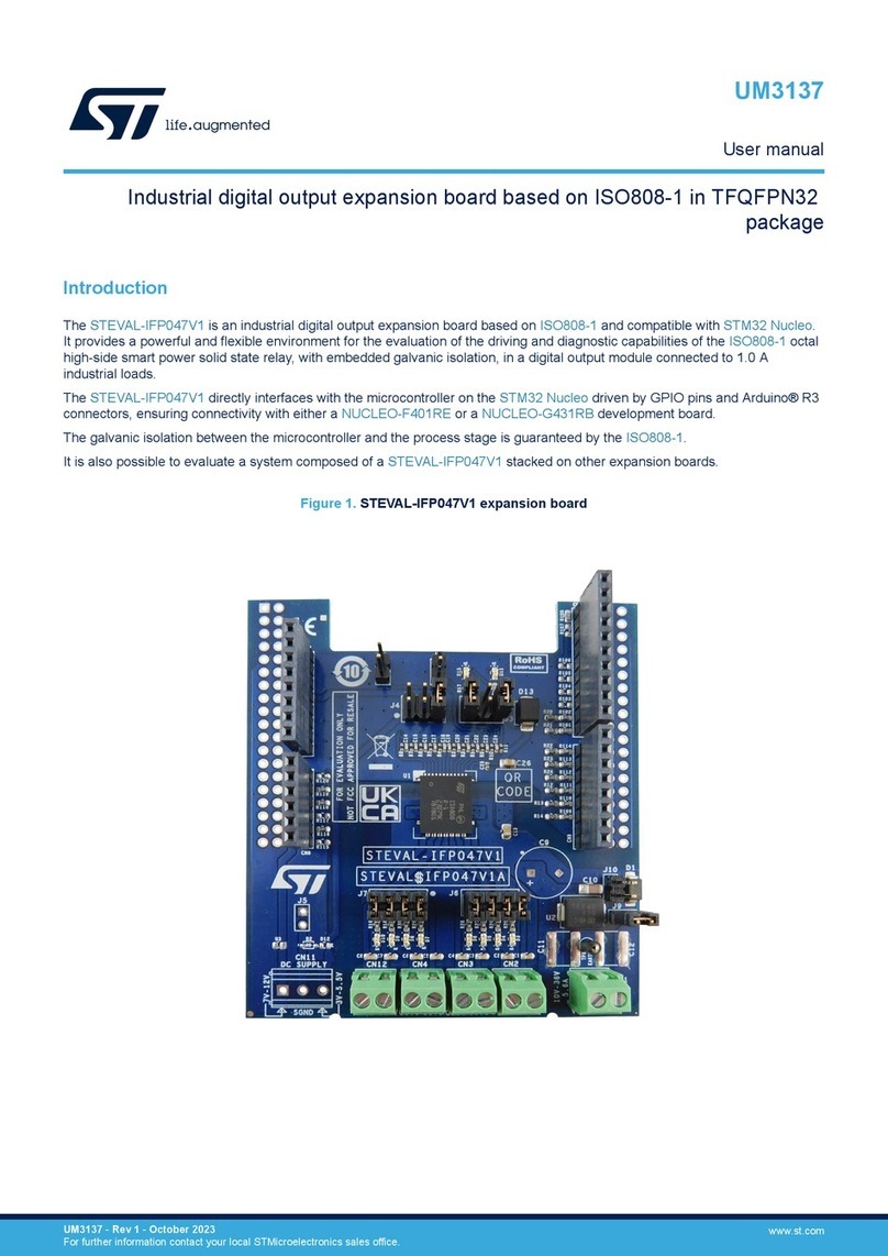
The STEVAL-PCC020V1 USB to I²C/UART board interfaces a Windows®-based PC with STNRG digital power supply
controllers such as STNRG011.
It is basically a bidirectional bridge between USB and I²C/UART buses and embeds an on-board power supply to communicate
and program the STNRG IC without need of mains.
The associated GUI allows monitoring the status of the digital controller in real-time and tuning specific parameters according to
customers' needs.
Figure 1. STEVAL-PCC020V1 interface board
Getting started with the STEVAL-PCC020V1: USB to I²C UART interface board
and associated GUI for STNRG products
UM2342
User manual
UM2342 - Rev 1 - February 2018
For further information contact your local STMicroelectronics sales office.
www.st.com/

1 Interface board aim
Figure 2. Customer typical application shows a customer typical application based on STNRG011 for the power
supply section.
The host microcontroller receives information only from the STNRG011 using an opto-isolated connection:
STNRG011 transmits metering information (instantaneous power) continuously, and the black box content at
reset.
Hence, the host microcontroller does not have access to the STNRG011 optional E²PROM where the patch and
black box history are stored.
Figure 2. Customer typical application
Figure 3. STNRG011 in demo/debug configuration shows the STNRG011 on the STEVAL-PCC020V1 interface
board or during debug configuration.
In the latter case, you can access the external optional E²PROM using the I²C protocol to program the associated
patches and reset the black box content.
You also have to access STNRG011 using UART bidirectional communication to:
• program the STNRG011 NVM content to change specific parameters according to customers’ needs
• display the system specific parameters in real-time to check its behavior during the debug and integration
phases.
UM2342
Interface board aim
UM2342 - Rev 1 page 2/57

Figure 3. STNRG011 in demo/debug configuration
To minimize STRGN011 pin count, UART and I²C interfaces share the same pins. The interfaces are not isolated
from the mains as they are located on the offline converter primary side.
Important: This adapter board is exclusively designed to interface with STNRG011 products.
In the final customer application, the tasks performed by the interface would be handled directly by the host
microcontroller or the application processor.
UM2342
Interface board aim
UM2342 - Rev 1 page 3/57

2 Getting started
2.1 STEVAL-PCC020V1 interface board overview
The STEVAL-PCC020V1 interface board key features are:
• Bidirectional communication between PC (USB) and STNRG011
• Self-powered from the USB line
• On-board 19 V generation for STNRG011 programming
• Electric Isolation between USB and other board electronics
• I²C bus running at up to 1 MHz
• A UART bus running at 19200 bps
• UART and I²C bus muxed together on the same interface
• On-board firmware upgrade through USB port
• Display power metrics (AC voltage, PFC power)
• Access to STNRG M24C32 optional E²PROM (used to store patch, calibration and event history data)
• Program NVM settings
• RoHS compliant
2.2 GUI overview
The GUI key features are:
•Runs on Windows XP, Windows 7 (.NET 4.0 framework needed)
• Real-time monitoring of the digital controller status
• Access to STNRG011 NVM parameters
• Access to STNRG011 external E²PROM for patch upload, calibration and event history
• Embedded PFC calibration wizard
2.3 Package contents
The STEVAL-PCC020V1 package includes:
• Hardware
– the interface board
– a 1.8 m USB A to USB mini-B cable
– a 15 cm 6-wire flat cable for target connection to the STNRG011 device
• Software
– USB drivers
– PC GUI installation package
Note: The complete software package is available at www.st.com.
2.4 System requirements
To use the STEVAL-PCC020V1 interface board, you need a PC with Windows® operating system.
The graphical user interface (GUI) works with Microsoft Windows XP or later versions and .NET Framework 4.0.
Note: The .NET Framework 4.0 is not included in the Windows XP installation package.
UM2342
Getting started
UM2342 - Rev 1 page 4/57

3 Hardware description and setup
3.1 Block diagram
Figure 4. STEVAL-PCC020V1 block diagram
3.2 Galvanic isolation
The STNRG011 has to be placed on the offline converter primary side: the galvanic isolation between the USB
and the remaining electronic of the board prevents any voltage from reaching the host PC and causing electrical
damage or interference.
3.3 Power supply
The STEVAL-PCC020V1 interface board is self-supplied via the 5 V USB connector.
This voltage directly supplies U3 and the related circuitry.
A dual isolated DC-DC module (U5) is used to supply the remaining part of the board, maintaining the isolation
among the PC and the target sides.
U5 generates two supplies, loosely regulated (+5 V and +20 V).
3.3.1 MCU subsystem supply (5 V)
The +5 V supply is later converted to a stable and clean +3V3 thanks to the linear regulator U6, which is always
on.
3.3.2 VCC generation (20 V)
The +20 V is always generated from +5 V and +15 V cascaded together (VOUT2- is referenced to VOUT1+ in
place of ground).
This voltage is later on supplied by the linear regulator U8 which has the following roles:
•to generate a stable +18.5 V;
• to act as a switch; U8 is enabled thanks to the MCU GPIO PA14 configured in open drain mode. When the
MCU wants to enable the VCC generation, PA14 is driven low.
D5 provides an OR-ing diode which, by default, is short-circuited by R17 resistor (0 W).
UM2342
Hardware description and setup
UM2342 - Rev 1 page 5/57

3.3.2.1 VCC soft start
At VCC generation switch on, VCC is typically decoupled by a 100 to 200 µF capacitor on the STNRG011 device.
If the regulator is switched on abruptly, an inrush current is generated that cannot be sustained by the upfront DC-
DC converter, which then enters current limitation.
Since the +20 V is generated by cascading +5 V and 15 V, the current limitation also impacts the +5 V supply
(hence the MCU).
When the MCU supply drops below the PowerOnReset threshold, the MCU resets and the board reboots.
To avoid this behavior, the linear regulator U8 is switched on via a soft start using a PWM enable signal (which
limits the current on the upfront DC-DC).
When VCC has reached a stable value (that is, the VCC capacitor is charged), the enable signal remains in the
steady-state condition (always on, so always low).
Soft start phase usually lasts about 120 ms.
Figure 5. VCC ramp-up typical waveform
3.3.2.2 NVM programming
The STEVAL-PCC020V1 interface board provides a VCC voltage to the target device that is high enough for an
NVM programming operation.
STNRG011 programming requirements are +18 V and 35 mA max. current.
If the VCC on the target device is < 17 V, the programming VCC can be simply connected to the target VCC
through a couple of OR-ing diodes.
The 19 V supply current delivered is limited to 100 mA by the on-board LDO (U8).
UM2342
Power supply
UM2342 - Rev 1 page 6/57

3.4 USB bridge
The communication between the STEVAL-PCC020V1 and the PC is managed by the latter as a standard serial
peripheral; the IC U3 converts the USB connection into a virtual COM port (refer to the electrical schematic).
By default, the virtual COM port operates at 921600 bps.
A yellow LED near the mini-B USB connector turns on when the CP2102 has been recognized (enumerated) by
the host operating system.
The VCP RX and TX signals are then isolated thanks to the opto-couplers U1 and U2 and connected to the
STM32F3 (U9) microcontroller USART1.
Important: The USB port and the remaining part of the board are isolated from the mains.
The microcontroller performs:
•Conversion between the host UART and I²C protocols
–The I²C speed can rise up to 1 MHz (maximum speed allowed by the STNRG011).
– The STM32F3 allows bidirectional communication between the PC and the target device through the
UART to I²C conversion.
•Conversion between the host UART and the STNRG011 UART .
This is mainly baud rate matching: STNRG011 operates at 19200 bps, whereas the host UART operates at
921600 bps.
Note: The microcontroller also manages the muxing of the UART and I²C protocols on the same interface.
3.5 VCC monitoring
The MCU also monitors the STNRG011 VCC line voltage.
STNRG011 VCC is sampled periodically by the MCU via a simple resistive bridge divider plus a low-pass filter
using R20, R21 and C19. The divider ratio is 10/78=1/7.8.
The divided voltage is then sent to STM32F3 PA0 pin on a regular 12-bit ADC.
For instance, this allows preventing the use of the on-board VCC when the STNRG011 is already operating.
Note: This feature accuracy is ±100 mV.
UM2342
USB bridge
UM2342 - Rev 1 page 7/57

4 Using the board
4.1 Board connectors, LEDs and buttons
Figure 6. STEVAL-PCC020V1 interface board connectors
Figure 7. STEVAL-PCC020V1 interface board status LEDs
Table 1. STEVAL-PCC020V1 LEDs (ON, OFF, blinking state)
D1 D2 D3 D4
ON OFF ON Blinking ON Blinking ON OFF
VCP
recognized by
the PC
VCP not
recognized/
inactive
Normal
operation
Firmware
error
Waiting for
the
STNRG011
frames
Receiving
STNRG011
frames
Internal VCC
enabled
Internal VCC
disabled
UM2342
Using the board
UM2342 - Rev 1 page 8/57

4.2 How to connect the STEVAL-PCC020V1 interface board to the offline converter
Figure 8. STEVAL-PCC020V1 interface board typical connection
Procedure Step 1. Connect the STEVAL-PCC020V1 interface board to a PC via a USB cable
Step 2. Connect the interface board and the offline converter board together through the 6-wire flat cable
Step 3. Connect the offline converter to the load
Step 4. Connect the mains
Caution:
You should never plug or unplug the interface board while the connection is running (for example, when the offline converter is
running). If the 5 V UART signals and +15 V VCC (typ.) are connected when the GND is not yet connected, the STNRG011 or
the interface board might be damaged.
UM2342
How to connect the STEVAL-PCC020V1 interface board to the offline converter
UM2342 - Rev 1 page 9/57

5 Software installation
You have to install the USB driver and the PC GUI before using the STEVAL-PCC020V1 interface board.
5.1 Virtual COM port driver installation (SiLabs CP2102)
To use the STEVAL-PCC020V1 interface board, first install one of the USB drivers located in the CD folder Driver
\CP210x_VCP_Windows:
• CP210xCVCPInstaller_x86.exe (for 32-bit OS)
• CP210xCVCPInstaller_x64.exe (for 64-bit OS)
Alternatively, you can find the latest version of the drivers at SiLabs.
When the interface board is plugged to the PC, the driver is automatically installed.
5.2 GUI installation
Procedure Step 1. Launch HVDPS-STNRG011-Setup.msi
Step 2. Follow the installation wizard instructions.
By default, the GUI is installed under C:\Program Files (x86)\STMicroelectronics\STNRG011 GUI\.
The GUI installer creates an icon in the Start menu, under STMicroelectronics\STNRG011.
Figure 9. HV-DPS GUI icon
Note: If a previous version of the software has already been installed, it must be uninstalled through the Windows
Control Panel Uninstall option.
UM2342
Software installation
UM2342 - Rev 1 page 10/57

6 GUI introduction
6.1 GUI features
The STNRG011 GUI is designed for debugging power supply applications.
It allows:
• reading instantaneous power metering information and PFC operating modes;
• reading and modifying STNRG011 NVM parameters defining the supply behavior (gain, fault management,
delays, PFC/LLC parameters, etc.);
• reading event history data (fault history, stored in optional E²P);
• programming optional E²P patches;
• accessing internal firmware variables (patch needed).
6.2 GUI startup screen
Figure 10. STNRG011 GUI startup screen
The GUI is split in the following areas:
1. Menu Bar: used to select the operation mode, i.e. to communicate with STNRG011, display logs, access
E2P directly, NVM programming, etc.
2. Metering or Event tabs: displays power metering information or event history
3. Traces and Status: internal debug traces and status bar showing the STNRG011 current status
6.3 Connection management
At startup, the GUI detects automatically the COM port to be used (the GUI selects the CP2102-based VCP).
In case of multiple CP2102, you have to manually select the right COM port via the COM Port menu.
You can also open or close the COM port via the menu shown below.
UM2342
GUI introduction
UM2342 - Rev 1 page 11/57

Figure 11. GUI COM port selection
Once the right COM port is selected, the GUI tries to communicate with the interface board microcontroller, as
shown below.
Figure 12. Traces during GUI connection
Once the microcontroller has been detected, the GUI displays the associated hardware and firmware version, and
build date.
Note: If the GUI does not find a SiLabs-based VCP, an error message appears. Check in the Device Manager if the
SiLabs VCP is correctly recognized by pressing plus Pause and selecting Device Manager, as shown in
the following figure.
UM2342
Connection management
UM2342 - Rev 1 page 12/57

Figure 13. SiLabs VCP in the Device Manager
6.4 GUI settings
You can access GUI settings through the Application→Settings menu.
UM2342
GUI settings
UM2342 - Rev 1 page 13/57

Figure 14. GUI Settings menu
Some settings (e.g. GUI refresh rate or power averaging) can be changed in real-time.
Pressing the Save Settings button saves the settings into the config.xml file.
Table 2. GUI setting parameters
Serial Port
UART Tx delay (ms) Optional Tx Delay. Leave it to 0ms
UART speed (ATE mode) STNRG011 UART speed during logging phase
UART speed (Normal mode) STNRG011 UART speed during ATE mode
Log UART messages from
STNRG011
Option to log the UART exchange on a file (uart_trace.txt on the GUI executable directory)
STNRG011
M24C32 E2P address Hardware address of the external E2P. STNRG011 is always assuming 4 (100)
ADC PFC_FB full scale Full scale equivalent value of the PFC_FB pin which is the voltage expected at the bulk
capacitor when the voltage at the PFC_FB pin is at the ADC full scale (2.5 V). Keep this
value if you are using the standard resistive bridge divider (9 MΩ/46.7 kΩ)
Default paths
Patches path Default path for the E2P patches
NVM path Default path for the NVM settings
UM2342
GUI settings
UM2342 - Rev 1 page 14/57

Serial Port
DefaultWatch files Default path for the Watch settings, used to monitor internal variables of the firmware
Default Pwr file Calibration file for the power metering
GUI settings
GUI refresh rate(1) Delay in ms between each GUI refresh
Concatenate commands(1) Messages sent to STNRG are concatenated to avoid USB overhead (Write1-
Write2..Read1-Read2 instead of Write1-Read1-Write2-Read2….)
STNRG011 periodic polling Periodically polls STNRG011 status
Power averaging Averaging filter for real-time power display
0 = No averaging 10 = Maximum averaging
1. Used only when Power Monitor window is active
UM2342
GUI settings
UM2342 - Rev 1 page 15/57

7 GUI normal mode
7.1 Power metering
During normal mode, STNRG011 sends the information used to compute the actual power delivered by the PFC,
that is:
• the estimated power computed by the power integration algorithm
• some factors used for power estimation correction :
– Vin (mains) voltage
– PFC mode of operations (DCM, Valley Skipping, TM)
– Time between PFC pulses (DCM mode only)
– Phase angle modulation ratio (at low power only)
• Some flags about temporary PFC faults (Deep DCM, PFC_OCP1, etc.)
Figure 15. GUI metering information panel
Note: If STNRG011 power messages are disabled, the boxes shown above are empty.
Important: Power metering is not available in Burst mode (to save MCU power energy, hence efficiency at low power).
7.2 PowerGraph report
By checking the box Display PowerGraph, the history of PowerGraph event is displayed, to see the long-term
stability of the power supply or mode changes versus load.
Figure 16. GUI PowerGraph report
UM2342
GUI normal mode
UM2342 - Rev 1 page 16/57

7.3 Event history and factory data pre-requisite: E²P
Event history and factory data are available only if an external E²PROM (M24C32) is connected to the
STNR0G11. This allows retrieving some information in case of system failures.
Since the fault history and factory data content is only sent at system power up, you have to turn the power supply
off and on to get the status.
However, if UART uplink communication is enabled (patch needed), it is possible to send a request to the
STNRG011 to immediately send the event and fault history by pressing the Get Factory Data button.
Another option is to directly read the E²P content (refer to Section 10.3 E²P parameter editor)
7.4 Faults history
The fault history is stored in the optional external E²P
.
Faults are stored in an 8-position circular buffer, hence only the last 8 faults are stored.
At each power up, the STNRG011 sends the content of the fault history (which is a sort of black box) to the host.
The GUI displays the fault in chronological order (the latest at the bottom).
Note: There are two types of faults:
• Standard fault→ 1 position per fault in the circular buffer
• Fault with debug information→ 2 positions per fault in the circular buffer; it provides more firmware
information.
Figure 17. GUI fault history
The number of faults stored depends on the fault type (between 4 and 8).
For instance, the figure above shows:
•a fault PFC_PFC_UVP with AC presence (position 3), which is using two positions in the buffer, and the
previous fault is at position 1
• two shutdown events (XCAP discharged→positions 4 and 5)
• a BrownOut event (Vac < 70 Vrms→position 6)
• two shutdown events (positions 7 and 0)
UM2342
Event history and factory data pre-requisite: E²P
UM2342 - Rev 1 page 17/57

7.5 Factory data display
Figure 18. GUI factory data panel
Like faults history, factory data are sent at each STNRG011 power up.
The table below shows the factory data parameters and lists some fields as examples for a possible user
application.
Table 3. GUI E²P parameter description
Voltage monitoring
Vout1
Customer factory field, not used by firmware nor GUI
Vout2
Vout3
Vout4
Calibration Data
PFC Voltage
Customer factory field, not used by firmware nor GUI
Wattage
L_Param PFC inductance, used by the power computation algorithm
Time Record
Running Time Power supply cumulated active time
On/Off Cycles Number of power supply restart events
Error Count Number of errors
Serial Number Data
Serial Number, 20 char Customer factory field, not used by firmware nor GUI
UM2342
Factory data display
UM2342 - Rev 1 page 18/57

8 Power metering calibration
8.1 Background
The STNRG011 provides to the host continuous power metering information about:
• PFC integrated power in raw format (resulting from the PID integrator)
• Input voltage
• PFC operating mode and skipping area
• PFC fault status
The instantaneous raw power estimation can be computed by:
PRawW=PFClsb ×128 ×
FSRVin
256
2
×
tsmed
L(1)
where
PRaw is the PFC power (not corrected)
PFClsb is the PFC integrated power in raw format
FSRVin is the full scale ADC voltage reading = 480 V
tsmed is the smed event (PFC timer) minimal duration = 1/60 MHz = 16.67 ns
L is the PFC inductor value (typically 250 µH on the evaluation board)
The raw power is almost proportional to the actual PFC power.
On the basis of the PFC mode and the input voltage, it is possible to correct the raw power to deduce the actual
power consumption.
As a lot of parameters have to be taken into account, a very simple approach is to use a calibration method for
each PFC operating mode.
The output power is also compensated with skipping area and input voltage, via the equation below:
Pout W=PRaw ×CMode ×CVin ×CPAM ×1 + CTdel (2)
where
PRaw is the raw power
CMode is the PFC mode correction factor (typically between 0.7 and 1)
CVin is the input voltage correction using a second order polynomial (a+b*Vin+c*Vin²). However since we typically
consider only two voltages (EU/US), the second order term is set to 0
CPAM is the skipping area correction factor (1 for no PAM, 0.26 for minimum PAM)
CTdel is the DCM mode correction using a first order equation (a+b*Tdel)
8.2 Metering calibration
To display the power metering correction factors described in the previous section, go to Application→Power
Metering Calibration menu; the GUI highlights the current PFC operating mode in yellow.
UM2342
Power metering calibration
UM2342 - Rev 1 page 19/57

Figure 19. GUI power metering calibration window
To calibrate the PFC mode parameters:
Procedure Step 1. Set a load to make the systems enter the transition mode (near nominal power, e.g. 150 W)
Step 2. Enter the associated reference power read on a precision power meter in the Ref Pwr box
Step 3. Press the Normalize button.
The GUI automatically computes and updates the correction factor associated to the current PFC
operating mode.
The power displayed in the GUI must be equal to the reference power.
This operation has to be repeated for every PFC mode (DCM, Valley#1/2/3)
The other parameters (PAM Correction, Tdel Correction, Vmains) have to be tuned manually.
UM2342
Metering calibration
UM2342 - Rev 1 page 20/57
Table of contents
Other ST Computer Hardware manuals

ST
ST ST25DV-DISCOVERY User manual

ST
ST AN5717 Installation and operating instructions

ST
ST X-NUCLEO-IHM03A1 User manual

ST
ST AEK-COM-ISOSPI1 User manual

ST
ST X-NUCLEO-OUT15A1 User manual

ST
ST STR91 Series Installation and operating instructions

ST
ST METERS AND MORE UM2241 User manual

ST
ST EVSPIN958 User manual

ST
ST STEVAL-IPFC02V1 User manual

ST
ST STEVAL-IFP047V1 User manual
Popular Computer Hardware manuals by other brands

elco
elco ELK22MP Instructions for use

Clas Ohlson
Clas Ohlson ExpressCard BU3020 instruction manual

National Instruments
National Instruments PXI-GPIB Getting started

Velopex
Velopex Extra-X quick start guide

TerraTec
TerraTec Cinergy T USB XE Quick setup guide

HP
HP Xw4400 - Workstation - 2 GB RAM installation guide