ST I-CUBE-LRWAN User manual

Introduction
This user manual describes the I-CUBE-LRWAN LoRaWAN® Expansion Package implementation on the STM32L0 Series,
STM32L1 Series, and STM32L4 Series microcontrollers. This document also explains how to interface with the LoRaWAN® to
manage the LoRa® wireless link.
LoRa® is a type of wireless telecommunication network designed to allow long-range communications at a very low bit-rate
and enabling long-life battery-operated sensors. LoRaWAN® defines the communication and security protocol that ensures
interoperability with the LoRa® network. The LoRaWAN® Expansion Package is compliant with the LoRa Alliance® specification
protocol named LoRaWAN®.
The I-CUBE-LRWAN main features are the following:
• Integration-ready application
•Easy add-on of the low-power LoRa® solution
• Extremely-low CPU load
• No latency requirements
• Small STM32 memory footprint
• Low-power timing services provided
The I-CUBE-LRWAN Expansion Package is based on the STM32Cube HAL drivers (Refer to LoRa standard overview).
This user manual provides customer examples on NUCLEO-L053R8, NUCLEO-L073RZ, NUCLEO-L152RE, and NUCLEO-
L476RG using Semtech expansion boards SX1276MB1MAS, SX1276MB1LAS, SX1272MB2DAS, SX1262DVK1DAS,
SX1262DVK1CAS, and SX1262DVK1BAS.
This document targets the following tools:
•P-NUCLEO-LRWAN1, STM32 Nucleo pack for LoRa® technology (Legacy only)
•P-NUCLEO-LRWAN2, STM32 Nucleo starter pack (USI®) for LoRa® technology
•P-NUCLEO-LRWAN3, STM32 Nucleo starter pack (RisingHF) for LoRa® technology
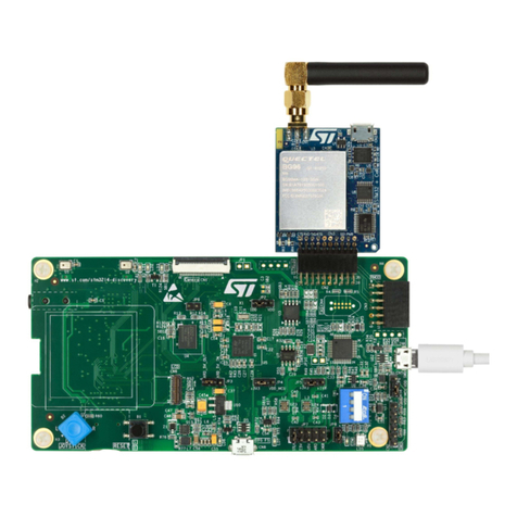
•B-L072Z-LRWAN1, STM32 Discovery kit embedding the CMWX1ZZABZ-091 LoRa® module from Murata
•I-NUCLEO-LRWAN1, LoRa® expansion board for STM32 Nucleo, based on the WM-SG-SM-42 LPWAN module (USI®)
available in P-NUCLEO-LRWAN2
• LRWAN-NS1, expansion board featuring the RisingHF modem RHF0M003 available in P-NUCLEO-LRWAN3
STM32 LoRaWAN® Expansion Package for STM32Cube
UM2073
User manual
UM2073 - Rev 12 - September 2021
For further information contact your local STMicroelectronics sales office.
www.st.com

1General information
The I-CUBE-LRWAN Expansion Package runs on STM32 32‑bit microcontrollers based on the Arm® Cortex®-M
processor.
Note: Arm is a registered trademark of Arm Limited (or its subsidiaries) in the US and/or elsewhere.
1.1 Terms and definitions
Table 1 presents the definitions of the acronyms that are relevant for a better contextual understanding of this
document.
Table 1. List of acronyms
Acronym Definition
ABP Activation by personalization
App Application
API Application programming interface
BSP Board support package
FSM Finite‑state machine
FUOTA Firmware update over the air
HAL Hardware abstraction layer
IoT Internet of things
LoRa®Long-range radio technology
LoRaWAN®LoRa® wide-area network
LPWAN Low-power wide-area network
MAC Media access control
MCPS MAC common part sublayer
MIB MAC information base
MLME MAC sublayer management entity
MPDU MAC protocol data unit
OTAA Over-the-air activation
PLME Physical sublayer management entity
PPDU Physical protocol data unit
SAP Service access point
SBSFU Secure Boot and Secure Firmware Update
UM2073
General information
UM2073 - Rev 12 page 2/52

1.2 Overview of available documents and references
Table 2 lists the complementary references for using I-CUBE-LRWAN.
Table 2. References
ID Description
[1] LoRa Alliance specification protocol named LoRaWAN version V1.0.3 July 2018 final release
[2] Low-Rate Wireless Personal Area Networks (LRWPANs) IEEE Std 802.15.4TM, 2011
[3] LoRaWAN® Regional Parameters v1.0.3revA, July 2018 release
[4] LoRa Alliance Fragmented Data Block Transport over LoRaWAN Specification v1.0.0 September 2018 [TS‑004]
[5] LoRa Alliance Remote Multicast Setup over LoRaWAN Specification v1.0.0 September 2018 [TS‑005]
[6] LoRa Alliance Application layer clock synchronization over LoRaWAN Specification v1.0.0 September 2018
[TS‑003]
[7] Application note Integration guide for the X-CUBE-SBSFU STM32Cube Expansion Package (AN5056)
[8] Application note I-CUBE-LRWAN embedding FUOTA, application implementation (AN5411)
[9] Application note Examples of AT commands on I-CUBE-LRWAN (AN4967)
[10] Application note How to build a LoRa® application with STM32CubeWL (AN5406)
[11] User manual Getting started with the P-NUCLEO-LRWAN2 and P-NUCLEO-LRWAN3 starter packs (UM2587)
[12] User manual STM32 Nucleo-64 boards (MB1136) (UM1724)
[13] User manual STM32WL Nucleo-64 board (MB1389) (UM2592)
[14] WM-SG-SM-42 AT Command Reference Manual located under USI_I-NUCLEO-LRWAN1(1)
[15] RHF-PS01709 LoRaWAN Class ABC AT-Command Specification available from RiSiNGHF home page(1)
1. This URL belongs to a third party. It is active at document publication, however, STMicroelectronics shall not be liable for
any change, move, or inactivation of the URL or the referenced material.
UM2073
Overview of available documents and references
UM2073 - Rev 12 page 3/52

2LoRa® standard overview
2.1 Overview
This section provides a general overview of the LoRa® and LoRaWAN® recommendations, particularly focusing
on the LoRa® end device that is the core subject of this user manual.
LoRa® is a type of wireless telecommunication network designed to allow long-range communication at a very
low bit rate and enabling long-life battery-operated sensors. LoRaWAN® defines the communication and security
protocol ensuring interoperability with the LoRa® network.
The LoRaWAN® Expansion Package is compliant with the LoRa Alliance® specification protocol named
LoRaWAN®.
Table 3 shows the LoRaWAN® class usage definition. Refer to Section 2.2.2 for further details on these classes.
Table 3. LoRaWAN® classes intended usage
Class name Intended usage
A - All
• Battery-powered sensors or actuators with no latency constraint
• Most energy-efficient communication class
• Must be supported by all devices
B - Beacon
• Battery-powered actuators
• Energy-efficient communication class for latency controlled downlink
• Based on slotted communication synchronized with a network beacon
C - Continuous
• Main powered actuators
• Devices that can afford to listen continuously
• No latency for downlink communication
Note: While the physical layer of LoRa® is proprietary, the rest of the protocol stack (LoRaWAN®) is kept open and its
development is carried out by the LoRa Alliance®.
2.2 Network architecture
The LoRaWAN® network is structured in a star of stars topology, where the end devices are connected via a
single LoRaWAN® link to one gateway as shown in Figure 1.
Figure 1. Network diagram
LoRaWAN® end device Gateway Network server Application server
Pet tracking
Smoke
alarm
Water meter
Trash
container
Vending machine
Gas
monitoring
UM2073
LoRa® standard overview
UM2073 - Rev 12 page 4/52

2.2.1 End-device architecture
The end device is composed of an RF transceiver (also known as radio) and a host STM32 MCU. The RF
transceiver is composed of a modem and an RF up-converter. The MCU implements the radio driver, the
LoRaWAN® stack and optionally the sensor drivers.
2.2.2 End-device classes
The LoRaWAN® has several different classes of end-point devices, addressing the different needs reflected in the
wide range of applications.
Bi-directional Class-A end devices (all devices)
• Class-A operation is the lowest power end-device system.
• Each end-device uplink transmission is followed by two short downlinks receive windows.
• Downlink communication from the server shortly after the end‑device has sent an uplink transmission (Refer
to Figure 2).
• Transmission slot is based on the own communication needs of the end device (ALOHA-type protocol).
Figure 2. Tx/Rx time diagram (Class-A)
Rx1 Rx2Tx
RxDelay2
RxDelay1
Bi-directional end‑devices with scheduled receive slots - Class-B - (beacon)
• Mid power consumption
• Class-B devices open extra receive windows at scheduled times (Refer to Figure 3).
• For the end device to open the receive window at the scheduled time, the end device receives a time-
synchronized beacon from the gateway.
• As Class‑A has priority, the device replaces the periodic ping slots with an uplink (Tx) sequence followed by
Rx1 or Rx2 received windows when required by the device.
Figure 3. Tx/Rx time diagram (Class-B)
Rx1 Rx2
Tx
RxDelay2
RxDelay1
PNG
BCN BCN
Beacon Period
Period Ping
PNG
UM2073
Network architecture
UM2073 - Rev 12 page 5/52

Bi-directional Class-C end devices with maximal receive slots (continuous)
• Large power consumption
• Class-C end devices have nearly continuously open receive windows, only closed when transmitting (Refer
to Figure 4).
Figure 4. Tx/Rx time diagram (Class-C)
RxC
Tx
RxDelay2
RxDelay1
Extends RxC until next uplink
On-air transmit time
Rx1 Rx2
RxC
RxC
2.2.3 End-device activation (joining)
Over-the-air activation (OTAA)
The OTAA is a joining procedure for the LoRaWAN® end device to participate in a LoRaWAN® network. Both the
LoRaWAN® end device and the application server share the same secret key known as AppKey. During a joining
procedure, the LoRaWAN® end device and the application server exchange inputs to generate two session keys:
• A network session key (NwkSKey) for MAC commands encryption
• An application session key (AppSKey) for application data encryption
Activation by personalization (ABP)
In the case of ABP, the NwkSkey and AppSkey are already stored in the LoRaWAN® end device that sends the
data directly to the LoRaWAN® network.
UM2073
Network architecture
UM2073 - Rev 12 page 6/52

2.2.4 Regional spectrum allocation
The LoRaWAN® specification varies slightly from region to region. The European, North American, and Asian
regions have different spectrum allocations and regulatory requirements (Refer to Table 4 for more details).
Table 4. LoRaWAN® regional spectrum allocation
Region Supported Band (MHz) Duty cycle (%) Output power
(dBm)(1)
EU Y 868 < 1 +13
EU Y 433 < 1 +10
US Y 915 No +27
CN N 779 < 0.1 +10
AS Y 923 No +13
IN Y 865 No +27
KR Y 920 No +11
RU Y 864 < 1 +13
AU Y 915 No +28
CN Y 470 No +17
1. The output power values are defined with the default maximal EIRP (Refer to the region associated section in [3]) and the
default antenna gain (2.15 by default): Default_Power = floor (Default_Max_EIRP - Default_Antenna_Gain)
UM2073
Network architecture
UM2073 - Rev 12 page 7/52

2.3 Network layer
The LoRaWAN® architecture is defined in terms of blocks, also called “layers”. Each layer is responsible for one
part of the standard and offers services to higher layers.
The end device is at least made of one physical layer (PHY), that embeds the radio frequency transceiver, a MAC
sublayer providing access to the physical channel, and an application layer, as shown in Figure 5.
Figure 5. LoRaWAN® layers
Upper layer
MAC
PHY
Physical medium (air interface)
2.3.1 Physical layer
The physical layer provides two services:
• The PHY data service, that enables the Tx/Rx of physical protocol data units (PPDUs)
• The PHY management service, that enables the personal area network information base (PIB) management
2.3.2 MAC sublayer
The MAC sublayer provides two services:
• The MAC data service, that enables the transmission and reception of MAC protocol data units (MPDU)
across the physical layer
• The MAC management service, that enables the PIB management
2.4 Message flow
This section describes the information flow between the N-user and the N-layer. The service request is performed
through a service primitive.
2.4.1 End-device activation details (joining)
Before communicating on the LoRaWAN® network, the end device must be associated or activated following one
of the two activation methods described in End-device activation (joining).
UM2073
Network layer
UM2073 - Rev 12 page 8/52

The message sequence chart (MSC) in Figure 6 shows the OTAA activation method.
Figure 6. Message sequence chart for joining (MLME primitives)
End-device
App layer
MLME.Req
(join request) Join request MLME.Ind
(join request)
Join response (ask)
MLME.Resp
(join accept)
MLME.Ind
(join accept)
MLME.Conf
(join accept)
MACWaitTimer
End-device App server
End-device
MAC layer
Network
MAC layer
Network
App layer
2.4.2 End-device class-A data communication
The end device transmits data by one of the following methods: through a confirmed-data message method
(Refer to Figure 7) or through an unconfirmed-data message (Refer to Figure 8).
In the first method, the end device requires an Ack (acknowledgment) to be done by the receiver while in the
second method, the Ack is not required.
When an end device sends data with an Ackreq (acknowledgment request), the end device must wait during an
acknowledgment duration AckWaitDuration to receive the acknowledgment frame (Refer to Section 4.3.1 ).
UM2073
Message flow
UM2073 - Rev 12 page 9/52

If the acknowledgment frame is received, then the transmission is successful, else the transmission failed.
Figure 7. Message sequence chart for confirmed data (MCPS primitives)
MCPS.Req
(data request)
Data (Ackreq=1)
Acknowledgment frame
MCPS.Ind (data)
MCPS.Conf()
AckWaitDuration
End device App Server
End-device
App layer
End-device
MAC layer
Network
MAC layer
Network
App layer
Figure 8. Message sequence chart for unconfirmed data (MCPS primitives)
End-device
App layer
MCPS.Req (data request) Data
(Ackreq=0)
MCPS.Ind (data)
MCPS.Conf()
End device App server
End-device
MAC layer
Network
MAC layer
Network
App layer
UM2073
Message flow
UM2073 - Rev 12 page 10/52

2.4.3 End-device class-B mode establishment
This section describes the LoRaWAN® class-B mode establishment. Class-B is achieved by having the gateway
sending a beacon on a 128 s regular basis to synchronize all the end devices in the network so that the end
device can open a short Rx window called a ping slot. The decision to switch from class-A to class-B always
comes from the application layer.
Figure 9. MSC MCPS class-B primitives
End device App
layer
End device MAC
layer
Network MAC
layer
Network App
layer
MCPS.Ind(Switch class-B)
Data (Class-B bit =1)
MCPS.Ind(Data)
MLME.Req(PingSlot.Req)
End Device App Server
MCPS.Req(Switch class-B)
MLME.Req( DeviceTime.Req)
MLME.Conf(DeviceTime.Ans)
DeviceTime.Ans
MLME.Req( Beacon_Acquisition)
Beacon lock
Nwk beacon Transmission
every 128 s
Beacon Acq
MLME.conf(PingSlot.Ans) PingSlot.Ans
MLME.Conf(Beacon_Acquisition)
Data (Switch class-B)
MCPS.Req(Switch class-B)
DeviceTimeReq
PingSlot.Req
UM2073
Message flow
UM2073 - Rev 12 page 11/52

2.5 Data flow
The data integrity is ensured by the network session key NwkSKey and the application session key AppSKey.
NwkSKey is used to encrypt and decrypt the MAC payload data and AppSKey is used to encrypt and decrypt the
application payload data. Refer to Figure 10 for the data flow representation.
Figure 10. Data flow
End device
(sensor – MCU – radio) Gateway
Encrypted payload by NwkSKey (payload of MAC data)
Encrypted payload by AppSKey (payload of application message)
IP infra IP infra
LoRa® RF
Application - data
Application - data
Network
server
Application
server
))) (((
NwkSKey is a private key that is derived from a root key and unique session identifier for each end device.
NwkSKey provides message integrity for the communication and provides security for the end device towards the
network server communication.
AppSKey is a private key that is derived from a root key and unique session identifier for each end device.
AppSKey is used to encrypt/decrypt the application data. In other words, AppSKey provides security for the
application payload. In this way, the application data sent by an end device cannot be interpreted by the network
server.
UM2073
Data flow
UM2073 - Rev 12 page 12/52

3I-CUBE-LRWAN middleware description
3.1 Overview
This I-CUBE-LRWAN Expansion Package offers a LoRaWAN® stack middleware for STM32 microcontrollers.
This middleware is split into several modules:
• LoRaMac layer module
• LoRaWAN® utility module
• LoRaWAN® crypto module
• LoRaMac handler
The LoRaMac handler module implements a LoRaWAN® state machine coming on top of the LoRaMac layer. The
LoRaWAN® stack module interfaces with the BSP Semtech radio driver module.
This middleware is provided in a source-code format and is compliant with the STM32Cube HAL driver.
Refer to Figure 11 for the project file structure.
Figure 11. Program file structure
BSP drivers for
Discovery kit
STM32L0 CMIS
system drivers
STM32L0 HAL drivers
Middleware
LoRaWAN®crypto engine
Middleware
LoRaMac handler
Middleware
LoRaMac layer
LoRaWAN®
AT_Slave application
Utilities modules
Middleware
LoRaWAN® Utilities
Middleware
SubGHz_Phy
LoRaWAN®
End_Node application
LoRaWAN®
FUOTA main application
STM32Cube_expansion_LRWAN
UM2073
I-CUBE-LRWAN middleware description
UM2073 - Rev 12 page 13/52

The I-CUBE-LRWAN Expansion Package includes:
• The LoRaWAN® stack middleware:
– LoRaWAN® layer
– LoRaWAN® utilities
– LoRaWAN® software crypto engine
– LoRaMac handler state machine
• Board support package:
– Radio Semtech drivers
– ST sensors drivers
• STM32L0xx HAL drivers
STM32L1xx HAL drivers
STM32L4xx HAL drivers
• Utilities:
– Tool sequencer provides services to manage tasks.
– Timer server provides timers service to the application.
– Low-power management provides power management service to the application.
– Trace provides trace capabilities to the application.
•LoRaWAN® applications:
– LoRaWAN_AT_Slave
– LoRaWAN_End_Node
– LoRaWAN_AT_Master
– LoraWAN_FUOTA
• SubGHz_Phy application:
– SubGig_Phy_PingPong
3.2 Features
• Compliant with the specification for the LoRa® Alliance protocol named LoRaWAN®
• On-board LoRaWAN® class‑A, class‑B, and class‑C protocol stack
• EU 868 MHz ISM band ETSI compliant
• EU 433 MHz ISM band ETSI compliant
• US 915 MHz ISM band FCC compliant
• KR 920 Mhz ISM band defined by the South Korean government
• RU 864 Mhz ISM band defined by Russian regulation
• AS 923 Mhz ISM band defined by Asian governments
• AU 915 Mhz ISM bands defined by the Australian government
• IN 865 Mhz ISM bands defined by the Indian government
• CN 470 Mhz ISM band defined by the People's Republic of China government
• CN 779 Mhz ISM band defined by the People's Republic of China government
• End-device activation either through over-the-air activation (OTAA) or through activation-by-personalization
(ABP)
• Adaptive data rate support
•LoRaWAN® test application for certification tests included
• Low-power optimized
UM2073
Features
UM2073 - Rev 12 page 14/52

3.3 Architecture
Figure 12 describes the main design of the firmware for the I-CUBE-LRWAN application.
Figure 12. Main design of the firmware
LmHandler
MAC layer
Radio driver
SX12xx driver
Utilities:
timer server
low-power
rand gen
Sensor
driver
Application (user)
GPIO RTCSPI I2C ADC
Provided by Semtech
HAL
LoRaWAN® middleware
Provided by ST and Semtech
Crypto/
software
secure
element
The HAL uses STM32Cube APIs to drive the MCU hardware required by the application. Only specific hardware
is included in the LoRaWAN® middleware as it is mandatory to run a LoRaWAN® application.
The RTC provides a centralized time unit that continues to run even in low-power mode (Stop mode). The RTC
alarm is used to wake up the system at specific timings managed by the timer server.
The radio driver uses the SPI and the GPIO hardware to control the radio (Refer to Figure 12). The radio driver
also provides a set of APIs to be used by higher-level software.
The LoRa® radio is provided by Semtech, though the APIs are slightly modified to interface with the STM32Cube
HAL.
The radio driver is split into two parts:
• The sx1276.c, sx1272.c and sx126x.c contain all functions that are radio dependent only.
• The sx1276mb1mas.c, sx1276mb1las, sx1272mb2das, sx1262dvk1das, sx1262dvk1cas and
sx1262dvk1bas contain all the radio board dependent functions.
The MAC controls the PHY using the 802.15.4 model. The MAC interfaces with the PHY driver and uses the timer
server to add or remove timed tasks and take care of the Tx time on-air. This action ensures that the duty-cycle
limitation mandated by the ETSI is respected and also carries out the AES encryption/decryption algorithm to
cipher the MAC header and the payload.
Since the state machine which controls the LoRaWAN® class‑A is sensitive, an intermediate level of software is
inserted (LmHandler.c) between the MAC and the application (Refer to MAC’s upper layer in Figure 12). With a
set of APIs limited as of now, the user is free to implement the class‑A state machine at the application level.
The application, built around an infinite loop, manages the low-power, runs the interrupt handlers (alarm or GPIO)
and calls the LoRaWAN® class‑A if any task must be done. All the running tasks are managed by the sequencer.
This application also implements sensor read access.
UM2073
Architecture
UM2073 - Rev 12 page 15/52

3.4 Hardware related components
3.4.1 Radio reset
One GPIO from the MCU is used to reset the radio. This action is done once at the initialization of the hardware
(Refer to Table 42 and Section 6.1 ).
3.4.2 SPI
The sx127x or sx126x radio commands and registers are accessed through the SPI bus at 1 Mbit/s (Refer to
Table 42 and Single MCU end-device hardware description).
3.4.3 RTC
The RTC calendar is used as a timer engine running in all power modes from the 32 kHz external oscillator. By
default, the RTC is programmed to provide 1024 ticks (sub-seconds) per second. The RTC is programmed once
at the initialization of the hardware when the MCU starts for the first time. The RTC output is limited to a 32-bit
timer that can last 48 days.
If the user needs to change the tick duration, note that the tick duration must remain below 1 ms.
3.4.4 Input lines
3.4.4.1 sx127x interrupt lines
Four sx127x interrupt lines are dedicated to receiving the interrupts from the radio (Refer to Table 42 and
Section 6.1 ).
The DIO0 is used to signal that the LoRa® radio completes a requested task (TxDone or RxDone).
The DIO1 is used to signal that the radio failed to complete a requested task (RxTimeout).
In FSK mode, a FIFO-level interrupt signals that the FIFO-level reached a predefined threshold and needs to be
flushed.
The DIO2 is used in FSK mode and signals that the radio successfully detected a preamble.
The DIO3 is reserved for future use.
Note: The FSK mode in LoRaWAN® has the fastest data rate at 50 Kbps.
3.4.4.2 sx126x input lines
The sx126x interface is simplified compared to sx127x. One busy signal informs the MCU that the radio is
busy and cannot treat any commands. The MCU must poll that the ready signal is deasserted before any new
command can be sent.
DIO1 is used as a single‑line interrupt.
UM2073
Hardware related components
UM2073 - Rev 12 page 16/52

4I-CUBE-LRWAN middleware programming guidelines
This section describes the LoRaMac layer APIs. The proprietary PHY layer (Refer to Section 2.1 Overview) is out
of the scope of this user manual and must be viewed as a black box.
4.1 Middleware initialization
The initialization of the LoRaMac layer is done through the LoraMacinitialization function. This function
does the preamble run time initialization of the LoRaMac layer and initializes the callback primitives of the MCPS
and MLME services (Refer to Table 5).
Table 5. Middleware initialization function
Function Description
LoRaMacStatus_t LoRaMacInitialization
(LoRaMacPrimitives_t *primitives,
LoRaMacCallback_t *callback,
LoRaMacRegion_t region)
Do initialization of the LoRaMac layer module (Refer to
Section 4.3 Middleware MAC layer callbacks)
4.2 Middleware MAC layer functions
The provided APIs follow the definition of primitive defined in [2].
The interfacing with the LoRaMac is made through the request-confirm and the indication-response architecture.
The application layer can perform a request that the LoRaWAN® MAC layer confirms with a confirm primitive.
Conversely, the LoRaWAN® MAC layer notifies an application layer with the indication primitive in case of any
event.
The application layer may respond to an indication with the response primitive. Therefore all the confirmations
and indications are implemented using callbacks.
The LoRaWAN® MAC layer provides MCPS services, MLME services, and MIB services.
4.2.1 MCPS services
The initialization of the LoRaMac layer is done through the LoraMacinitialization function. This function
does the preamble run time initialization of the LoRaMac layer and initializes the callback primitives of the MCPS
and MLME services (Refer to Table 6).
Table 6. MCPS services function
Function Description
LoRaMacStatus_t
LoRaMacMcpsRequest( McpsReq_t*
mcpsRequest, bool allowDelayedTx)
Requests to send Tx data
4.2.2 MLME services
The LoRaWAN® MAC layer uses the MLME services to manage the LoRaWAN® network (Refer to Table 7).
Table 7. MLME services function
Function Description
LoRaMacStatus_t LoRaMacMlmeRequest
(MlmeReq_t *mlmeRequest) Used to generate a join request or request for a link check
UM2073
I-CUBE-LRWAN middleware programming guidelines
UM2073 - Rev 12 page 17/52

4.2.3 MIB services
The MIB stores important runtime information, such as MIB_NETWORK_ACTIVATION, or MIB_NET_ID, and
holds the configuration of the LoRaWAN® MAC layer, for example, MIB_ADR or MIB_APP_KEY. The provided
APIs are presented in Table 8.
Table 8. MLME services function
Function Description
LoRaMacStatus_t
LoRaMacMibSetRequestConfirm
(MibRequestConfirm_t *mibSet)
To set attributes of the LoRaMac layer
LoRaMacStatus_t
LoRaMacMibGetRequestConfirm
(MibRequestConfirm_t *mibGet)
To get attributes of the LoRaMac layer
4.3 Middleware MAC layer callbacks
Refer to Section 4.1 Middleware initialization for the description of the LoRaMac user event functions primitives
and the callback functions.
4.3.1 MCPS
In general, the LoRaWAN® MAC layer uses the MCPS services for data transmission and data reception (Refer to
Table 9).
Table 9. MCPS primitives
Function Description
void (*MacMcpsConfirm)
(McpsConfirm_t *McpsConfirm)
*McpsIndication)
Event function primitive for the called callback to be implemented by the
application. Response to a McpsRequest
Void (*MacMcpsIndication)
(McpsIndication_t
Event function primitive for the called callback to be implemented by the
application. Notifies application that a received packet is available
4.3.2 MLME
The LoRaWAN® MAC layer uses the MLME services to manage the LoRaWAN® network (Refer to Table 10).
Table 10. MLME primitive
Function Description
void (*MacMlmeConfirm) (MlmeConfirm_t
*MlmeConfirm)
Event function primitive so-called callback to be implemented
by the application
4.3.3 MIB
No available function.
4.3.4 Battery level
The LoRaWAN® MAC layer needs a battery-level measuring service (Refer to Table 11).
Table 11. Battery level function
Function Description
uint8_t GetBatteryLevel (void) Get the measured battery level
UM2073
Middleware MAC layer callbacks
UM2073 - Rev 12 page 18/52

4.4 Middleware MAC layer timers
4.4.1 Rx-delay window
Refer to Section 2.2.2 End-device classes. Refer to Table 12 for the Rx-delay functions.
Table 12. Rx-delay functions
Function Description
void OnRxWindow1TimerEvent (void) Set the RxDelay1
(ReceiveDelayX - RADIO_WAKEUP_TIME)
void OnRxWindow2TimerEvent (void) Set the RxDelay2
4.4.2 Delay for Tx frame transmission
Table 13. Delay for Tx frame transmission
Function Description
void OnTxDelayedTimerEvent (void) Set timer for Tx frame transmission
4.4.3 Delay for Rx frame
Table 14. Delay for Rx frame function
Function Description
void OnAckTimeoutTimerEvent (void) Set timeout for received frame acknowledgment
4.5 Emulated secure element
The proposed hardware platforms do not integrate a secure-element device. Therefore this secure‑element
device is emulated by software. Figure 13 describes the main design of the LoRaMacCrypto module.
Figure 13. LoRaMacCrypto module design
LoRaMacCrypto
LoRaMac
Message
serializer
Message
parser
Message preparation Nonce handling
Key-ID selection Frame counter
verification
Software Secure Element
Key storage Encryption
Key derivation CMAC computation
Key provisioning CMAC verification
LoRaMacCrypto.h
secure-element.h
UM2073
Middleware MAC layer timers
UM2073 - Rev 12 page 19/52

The APIs presented in Table 15 are used to manage the emulated secure element.
Table 15. Secure-element functions
Function Description
SecureElementStatus_t
SecureElementInit
(EventNvmCtxChanged seNvmCtxChanged)
Initialization of the secure-element driver
The Callback function is called when the non-volatile context
must be stored.
SecureElementStatus_t
SecureElementRestoreNvmCtx (void*
seNvmCtx)
Restore the internal nvm context from passed pointer to non-
volatile module context to be restored.
void* SecureElementGetNvmCtx
(size_t* seNvmCtxSize) Request address where the non-volatile context is stored.
SecureElementStatus_t
SecureElementSetKey (KeyIdentifier_t
keyID, uint8_t* key)
Set a key.
SecureElementStatus_t
SecureElementComputeAesCmac (uint8_t*
buffer, uint16_t size, KeyIdentifier_t
keyID, uint32_t* cmac)
Compute a CMAC.
The Key‑ID determines the AES key to use.
SecureElementStatus_t
SecureElementVerifyAesCmac (uint8_t*
buffer, uint16_t size, uint32_t
expectedCmac, KeyIdentifier_t keyID)
Compute cmac and compare with expected cmac.
The KeyID determines the AES key to use.
SecureElementStatus_t
SecureElementAesEncrypt (uint8_t*
buffer, uint16_t size, KeyIdentifier_t
keyID, uint8_t* encBuffer)
Encrypt a buffer.
The KeyID determines the AES key to use.
SecureElementStatus_t
SecureElementDeriveAndStoreKey
(Version_t version, uint8_t*
input, KeyIdentifier_t rootKeyID,
KeyIdentifier_t targetKeyID)
Derive and store a key. The key derivation depends on the
LoRaWAN® versionKeyID, rootKeyID are used to identify the
root key to perform the derivation.
4.6 Middleware LmHandler application function
The interface to the MAC is done through the MAC interface file LoRaMac.h.
Standard mode
In standard mode, an interface file (Refer to LmHandler in Figure 12) is provided to let the user start without
worrying about the LoRaWAN® state machine. The interface file is located in Middlewares\Third_Party\LoR
aWAN\LmHandler\LmHandler.c.
The interface file implements:
• A set of APIs allowing access to the LoRaWAN® MAC services
• The LoRaWAN® certification test cases that are not visible to the application layer
Advanced mode
In this mode, the user accesses directly the MAC layer by including the MAC in the user file.
UM2073
Middleware LmHandler application function
UM2073 - Rev 12 page 20/52
Table of contents
Other ST Computer Hardware manuals
Popular Computer Hardware manuals by other brands

Simonds
Simonds CLP-274 Owners & safety manual

Seagate
Seagate Nytro 5350S NVMe SSD product manual

Avalue Technology
Avalue Technology ECM-TGUC user manual

PS Audio
PS Audio MultiWave II Installation and operation instructions

ekwb
ekwb EK-Quantum Vector FE RTX 3070 user guide

Cypress
Cypress CY62167DV18 Specification sheet