ST EVALSP1310CPU User manual

November 2012 Doc ID 023872 Rev 1 1/36
UM1585
User manual
EVALSP1310CPU
evaluation board, hardware revision 1
Introduction
This document applies to hardware revision 1 evaluation boards.
This evaluation board is intended to be used to:
●enable quick evaluation and debugging of software for the SPEAr1310 rev.C embedded
MPU family
●act as a learning tool for rapid familiarity with the features of the SPEAr1310 rev.C
●provide a reference design to use as a starting point for the development of a final
application board
The EVALSP1310CPU board is equipped with interfaces to the high speed peripherals
embedded in SPEAr1310 rev. C devices.
Through an expansion connector it is possible to plug in dedicated expansion boards
(EVALBASEXP) and/or FPGA boards (EVALSP13xxFPGA) for developing customer-
specific IPs.
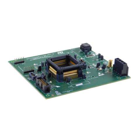
Figure 1. EVALSP1310CPU board rev. 1
www.st.com

Contents UM1585
2/36 Doc ID 023872 Rev 1
Contents
1 Kit contents . . . . . . . . . . . . . . . . . . . . . . . . . . . . . . . . . . . . . . . . . . . . . . . . 6
2 Features and block diagram . . . . . . . . . . . . . . . . . . . . . . . . . . . . . . . . . . . 7
2.1 Board features . . . . . . . . . . . . . . . . . . . . . . . . . . . . . . . . . . . . . . . . . . . . . . 7
2.2 Connectors, jumpers and pushbuttons . . . . . . . . . . . . . . . . . . . . . . . . . . . . 8
3 Getting started . . . . . . . . . . . . . . . . . . . . . . . . . . . . . . . . . . . . . . . . . . . . . . 9
3.1 Connecting . . . . . . . . . . . . . . . . . . . . . . . . . . . . . . . . . . . . . . . . . . . . . . . . . 9
3.2 Booting . . . . . . . . . . . . . . . . . . . . . . . . . . . . . . . . . . . . . . . . . . . . . . . . . . . . 9
3.3 Serial interface . . . . . . . . . . . . . . . . . . . . . . . . . . . . . . . . . . . . . . . . . . . . . . 9
3.4 Reset switch . . . . . . . . . . . . . . . . . . . . . . . . . . . . . . . . . . . . . . . . . . . . . . . 10
4 Block descriptions . . . . . . . . . . . . . . . . . . . . . . . . . . . . . . . . . . . . . . . . . 11
4.1 General power supply . . . . . . . . . . . . . . . . . . . . . . . . . . . . . . . . . . . . . . . 11
4.1.1 Power LEDs . . . . . . . . . . . . . . . . . . . . . . . . . . . . . . . . . . . . . . . . . . . . . . 12
4.2 Dynamic memory subsystem . . . . . . . . . . . . . . . . . . . . . . . . . . . . . . . . . . 12
4.3 Static memory subsystem . . . . . . . . . . . . . . . . . . . . . . . . . . . . . . . . . . . . 13
4.3.1 Serial Flash . . . . . . . . . . . . . . . . . . . . . . . . . . . . . . . . . . . . . . . . . . . . . . 13
4.3.2 NAND Flash . . . . . . . . . . . . . . . . . . . . . . . . . . . . . . . . . . . . . . . . . . . . . . 13
4.3.3 NAND Flash expansion . . . . . . . . . . . . . . . . . . . . . . . . . . . . . . . . . . . . . 13
4.4 PCIe/SATA . . . . . . . . . . . . . . . . . . . . . . . . . . . . . . . . . . . . . . . . . . . . . . . . 14
4.4.1 PCIe clock . . . . . . . . . . . . . . . . . . . . . . . . . . . . . . . . . . . . . . . . . . . . . . . 14
4.5 Ethernet subsystem . . . . . . . . . . . . . . . . . . . . . . . . . . . . . . . . . . . . . . . . . 15
4.5.1 Configuration jumpers and switches . . . . . . . . . . . . . . . . . . . . . . . . . . . 15
4.5.2 Ethernet LEDs . . . . . . . . . . . . . . . . . . . . . . . . . . . . . . . . . . . . . . . . . . . . 18
5 USB 2.0 subsystem . . . . . . . . . . . . . . . . . . . . . . . . . . . . . . . . . . . . . . . . . 19
5.1 Host ports . . . . . . . . . . . . . . . . . . . . . . . . . . . . . . . . . . . . . . . . . . . . . . . . . 19
5.2 Host LEDs . . . . . . . . . . . . . . . . . . . . . . . . . . . . . . . . . . . . . . . . . . . . . . . . 19
5.3 OTG USB . . . . . . . . . . . . . . . . . . . . . . . . . . . . . . . . . . . . . . . . . . . . . . . . . 19
5.3.1 SPEAr USB interface power . . . . . . . . . . . . . . . . . . . . . . . . . . . . . . . . . 19
6 A/D Interface . . . . . . . . . . . . . . . . . . . . . . . . . . . . . . . . . . . . . . . . . . . . . . 21


UM1585 Contents
Doc ID 023872 Rev 1 3/36
7 RTC (battery connector) . . . . . . . . . . . . . . . . . . . . . . . . . . . . . . . . . . . . . 21
8 Expansion connectors . . . . . . . . . . . . . . . . . . . . . . . . . . . . . . . . . . . . . . 22
9 Debug interface . . . . . . . . . . . . . . . . . . . . . . . . . . . . . . . . . . . . . . . . . . . . 24
10 Strapping options . . . . . . . . . . . . . . . . . . . . . . . . . . . . . . . . . . . . . . . . . . 25
11 Test modes . . . . . . . . . . . . . . . . . . . . . . . . . . . . . . . . . . . . . . . . . . . . . . . . 26
12 LEDs . . . . . . . . . . . . . . . . . . . . . . . . . . . . . . . . . . . . . . . . . . . . . . . . . . . . . 27
13 Jumper descriptions . . . . . . . . . . . . . . . . . . . . . . . . . . . . . . . . . . . . . . . . 28
14 Connectors . . . . . . . . . . . . . . . . . . . . . . . . . . . . . . . . . . . . . . . . . . . . . . . 29
15 Pushbuttons . . . . . . . . . . . . . . . . . . . . . . . . . . . . . . . . . . . . . . . . . . . . . . 29
Appendix A Licence agreements . . . . . . . . . . . . . . . . . . . . . . . . . . . . . . . . . . . . . 30
Revision history . . . . . . . . . . . . . . . . . . . . . . . . . . . . . . . . . . . . . . . . . . . . . . . . . . . . 35

List of figures UM1585
4/36 Doc ID 023872 Rev 1
List of figures
Figure 1. EVALSP1310CPU board rev. 1 . . . . . . . . . . . . . . . . . . . . . . . . . . . . . . . . . . . . . . . . . . . . . . 1
Figure 2. Block diagram . . . . . . . . . . . . . . . . . . . . . . . . . . . . . . . . . . . . . . . . . . . . . . . . . . . . . . . . . . . . 7
Figure 3. Connector, jumper and push button locations (top) . . . . . . . . . . . . . . . . . . . . . . . . . . . . . . . 8
Figure 4. Serial cable setting (J17) . . . . . . . . . . . . . . . . . . . . . . . . . . . . . . . . . . . . . . . . . . . . . . . . . . 10
Figure 5. Serial Flash M25P64 (U1) and M25P40 (U3) enable . . . . . . . . . . . . . . . . . . . . . . . . . . . . . 13
Figure 6. NAND Flash selection. . . . . . . . . . . . . . . . . . . . . . . . . . . . . . . . . . . . . . . . . . . . . . . . . . . . . 13
Figure 7. NAND Flash device voltage selector . . . . . . . . . . . . . . . . . . . . . . . . . . . . . . . . . . . . . . . . . 14
Figure 8. SPEAr NAND Flash I/O voltage selector . . . . . . . . . . . . . . . . . . . . . . . . . . . . . . . . . . . . . . 14
Figure 9. SPEAr MIPHY PLL power selectors . . . . . . . . . . . . . . . . . . . . . . . . . . . . . . . . . . . . . . . . . . 14
Figure 10. SPEAr GMII I/F voltage selector. . . . . . . . . . . . . . . . . . . . . . . . . . . . . . . . . . . . . . . . . . . . . 16
Figure 11. Gigabit PHY Ethernet voltage selector . . . . . . . . . . . . . . . . . . . . . . . . . . . . . . . . . . . . . . . . 16
Figure 12. DP83865 clock output selector . . . . . . . . . . . . . . . . . . . . . . . . . . . . . . . . . . . . . . . . . . . . . . 17
Figure 13. SPEAr USB phy power selector . . . . . . . . . . . . . . . . . . . . . . . . . . . . . . . . . . . . . . . . . . . . . 20
Figure 14. Samtec connector. . . . . . . . . . . . . . . . . . . . . . . . . . . . . . . . . . . . . . . . . . . . . . . . . . . . . . . . 22

UM1585 List of tables
Doc ID 023872 Rev 1 5/36
List of tables
Table 1. Common power rails. . . . . . . . . . . . . . . . . . . . . . . . . . . . . . . . . . . . . . . . . . . . . . . . . . . . . . 11
Table 2. Power LEDs . . . . . . . . . . . . . . . . . . . . . . . . . . . . . . . . . . . . . . . . . . . . . . . . . . . . . . . . . . . . 12
Table 3. J1 NAND expansion connector pin assignment . . . . . . . . . . . . . . . . . . . . . . . . . . . . . . . . . 13
Table 4. PCIe clock settings (default settings) . . . . . . . . . . . . . . . . . . . . . . . . . . . . . . . . . . . . . . . . . 15
Table 5. Switch 1 configuration. . . . . . . . . . . . . . . . . . . . . . . . . . . . . . . . . . . . . . . . . . . . . . . . . . . . . 15
Table 6. Jumper configurations . . . . . . . . . . . . . . . . . . . . . . . . . . . . . . . . . . . . . . . . . . . . . . . . . . . . 16
Table 7. DP83865, MAC interface setting . . . . . . . . . . . . . . . . . . . . . . . . . . . . . . . . . . . . . . . . . . . . 17
Table 8. Auto-negotiation disabled . . . . . . . . . . . . . . . . . . . . . . . . . . . . . . . . . . . . . . . . . . . . . . . . . . 17
Table 9. Auto-negotiation enabled . . . . . . . . . . . . . . . . . . . . . . . . . . . . . . . . . . . . . . . . . . . . . . . . . . 17
Table 10. Ethernet LEDs . . . . . . . . . . . . . . . . . . . . . . . . . . . . . . . . . . . . . . . . . . . . . . . . . . . . . . . . . . 18
Table 11. USB host LEDs. . . . . . . . . . . . . . . . . . . . . . . . . . . . . . . . . . . . . . . . . . . . . . . . . . . . . . . . . . 19
Table 12. OTG micro USB-AB LEDs . . . . . . . . . . . . . . . . . . . . . . . . . . . . . . . . . . . . . . . . . . . . . . . . . 19
Table 13. J14 (20) ADC connector A2D . . . . . . . . . . . . . . . . . . . . . . . . . . . . . . . . . . . . . . . . . . . . . . . 21
Table 14. Expansion connector functions - EXPI mode enabled . . . . . . . . . . . . . . . . . . . . . . . . . . . . 22
Table 15. Expansion connector functions - EXPI mode not enabled . . . . . . . . . . . . . . . . . . . . . . . . . 23
Table 16. J15 JTAG connector pin-out . . . . . . . . . . . . . . . . . . . . . . . . . . . . . . . . . . . . . . . . . . . . . . . . 24
Table 17. Debug mode selection . . . . . . . . . . . . . . . . . . . . . . . . . . . . . . . . . . . . . . . . . . . . . . . . . . . . 24
Table 18. Switch 3 (SW3) configuration . . . . . . . . . . . . . . . . . . . . . . . . . . . . . . . . . . . . . . . . . . . . . . . 25
Table 19. Switch 4 (SW4) configuration . . . . . . . . . . . . . . . . . . . . . . . . . . . . . . . . . . . . . . . . . . . . . . . 25
Table 20. Software boot options . . . . . . . . . . . . . . . . . . . . . . . . . . . . . . . . . . . . . . . . . . . . . . . . . . . . . 25
Table 21. Test modes . . . . . . . . . . . . . . . . . . . . . . . . . . . . . . . . . . . . . . . . . . . . . . . . . . . . . . . . . . . . . 26
Table 22. Status LEDs . . . . . . . . . . . . . . . . . . . . . . . . . . . . . . . . . . . . . . . . . . . . . . . . . . . . . . . . . . . . 27
Table 23. List of board jumpers . . . . . . . . . . . . . . . . . . . . . . . . . . . . . . . . . . . . . . . . . . . . . . . . . . . . . 28
Table 24. List of board connectors . . . . . . . . . . . . . . . . . . . . . . . . . . . . . . . . . . . . . . . . . . . . . . . . . . . 29
Table 25. Document revision history . . . . . . . . . . . . . . . . . . . . . . . . . . . . . . . . . . . . . . . . . . . . . . . . . 35

Kit contents UM1585
6/36 Doc ID 023872 Rev 1
1 Kit contents
●EVALSP1310CPU board
●AC adapter (output voltage 5 V 2A)
●2 power adapter plugs (USA/Europe)

UM1585 Features and block diagram
Doc ID 023872 Rev 1 7/36
2 Features and block diagram
2.1 Board features
●SPEAr1310 SoC CPU
●Dedicated 16/32-bit trace port (program trace)
●Five DDR3 chips (32-bit width plus ECC), 1 GB
●Serial NOR Flash, 8 MB
●Serial NOR Flash 512 KB
●8-bit NAND Flash, 256 MB
●16-bit NAND Flash expansion connector
●Two USB 2.0 full speed Host ports
●One OTG 2.0 high speed port (Micro USB-AB)
●One 10/100/1000 Ethernet port
●One SATA connector
●One PCIe X1 Endpoint
●One PCIe X1 Root Complex connector
●One Serial port (up to 115 Kbaud)
●Debug ports (CPU JTAG & CoreSight)
●8 ADC channels (10 bit, 1 Msamples/s)
●Expansion connector
Figure 2. Block diagram
Trace
debug
NOR
Flash
SPEAr1310
NOR
Flash
NAND
Flash 8-bit
JTAG
debug
Trace
debug
UART
A2D 8 channels
NAND Flash
exp. Conn.
8/16-bit
Core
power
supply
Power combo
PM6641 (3V3,
2V5, 1V5)
ETH PHY
10/100/
1000
ETH
connector
USB 2.0
Host 1&2
USB OTG
SATA
PCIe root
complex
PCIe end
point
DDR3
DDR3
DDR3
DDR3
DDR3
FSMC-LCD-MAC
Expansion connector

Features and block diagram UM1585
8/36 Doc ID 023872 Rev 1
2.2 Connectors, jumpers and pushbuttons
Figure 3. Connector, jumper and push button locations (top)

UM1585 Getting started
Doc ID 023872 Rev 1 9/36
3 Getting started
Caution: This board contains electrostatic-sensitive devices
The EVALSP1310CPU board is shipped in protective anti-static packaging. Do not submit
the board to high electrostatic potentials, and follow good practices for working with static
sensitive devices.
●Wear an anti-static wristband. Wearing a simple anti-static wristband can help to
prevent ESD from damaging the board.
●Zero potential. Always touch a grounded conducting material before handling the
board, and periodically while handling it.
●Use an anti-static mat. When configuring the board, place it on an anti-static mat to
reduce the possibility of ESD damage.
●Handle only the edges. Handle the board by its edges only, and avoid touching board
components.
3.1 Connecting
1. Connect a serial cable adapter (RS232 on J16) to a host PC (see Primary Serial cable
setting).
2. On a host PC running Windows or Linux, start the Terminal program.
3. Connect the AC adapter to a power outlet.
4. Power on the board (plug the AC adapter jack into J12). A sequence of boot messages
displays, followed by the Linux console prompt.
Software user manuals are available on request; contact your local ST representative.
3.2 Booting
The EVALSP1310CPU board can boot a Linux kernel pre-installed in the serial NOR Flash.
At power on, the serial port outputs a brief header message with some uBoot information
(uBoot version, SDK version, and some internal hardware information). At this point, you
can choose to:
●Stop the system directly in uBoot
To do this, press the spacebar on the host computer keyboard before the boot delay
time expires (default is 3 seconds).
●Boot Linux
The system logs you in automatically as super user, and the Linux shell prompt
displays on the screen.
3.3 Serial interface
A serial interface, which can typically be used to connect an operating system monitor
console, is available on the J16 connector.

Getting started UM1585
10/36 Doc ID 023872 Rev 1
It is possible to simulate a cross cable by changing the position of the J17 jumpers as shown
below.
Refer to the schematic drawing (contact your local ST representative for availability), for the
pin-out of the connectors.
Figure 4. Serial cable setting (J17)
3.4 Reset switch
A manual reset switch (P1) is available on the top side of the board.
Cross
cable
J17
12
34
J17
12
34
modem
cable
Null

UM1585 Block descriptions
Doc ID 023872 Rev 1 11/36
4 Block descriptions
4.1 General power supply
The power supply block generates all the required voltages from a 5 V external AC/DC. The
generated voltages are:
●5 V obtained from an over voltage protection device with thermal shutdown
●1.2 V, generated from 5 V with a step-down switching regulator
●1.5 V, 2.5 V, and 3.3 V generated from 5 V with a multi-output switching regulator
●12 V generated from 5 V with a set-up converter
●1.8 V generated from 3.3 V with a low drop voltage regulator
Table 1. Common power rails
Name Use
Jumper
for current
measurement
+5V J13: Alternate power input connector
J11: Expansion connector
VDD1V2 SPEAr core (SPEAr_VDD1V2)
SPEAr DDR3 interface (SPEAr_DDR3_1V2)
JP31
JP30
VDD1V5
DDR3 chips
SPEAr DDR I/O (SPEAr_DDR3_1V5)
SPEAr RTC (RTC_VDD1V5)
-
JP32
JP39
VDD1V8
GigaPhy chip
SPEAr 1.8 V NAND8 Flash (JP3: Close 2&3 for 1.8 V)
NAND Flash chip (Close 2&3 of JP2 for 1.8V)
NAND expansion connector (Close2&3 of JP3)
-
JP3(2-3)
VDD2V5
SPEAr_OTP antifuses (JP1: Close 1&2 to supply)
SPEAr GMII interface(JP16: Close 2&3 for 2.5V)
SPEAr PCIe (JP24 close and JP5: Close 2&3 for ext power)
SPEAr A2D_PLLs_VDD2V5
SPEAr USB_VDD2V5
A2D connector
Ethernet RJ45 (J2)
Giga PHY (JP42 close 2&3)
JP33
JP1(1-2)
JP16(2-3)
VDD3V3
SPEAr (SPEAr_VDD3V3)
PCIe Clock Source
JTAG MIPHY connector
Giga PHY (JP42 close 1&2)
Serial NOR Flash
NAND Flash chip (Close 1&2 of JP2 for 3.3V)
NAND expansion connector (Close1&2 of JP3)
CPU JTAG & trace connectors
JP34

Block descriptions UM1585
12/36 Doc ID 023872 Rev 1
4.1.1 Power LEDs
A low-power supervisory device monitors the power supplies and generates a reset signal.
4.2 Dynamic memory subsystem
Five Micron DDR3 chips (MT41J256M8) are used: four for data (32-bit width), and one for
ECC.
Total size available is 4 chips x 32 Mb x 8 x 8 banks = 1 Gbyte.
VDD3V3_HOST PCIe x1 connectors
+12V_HOST PCIe x1 connectors
Table 1. Common power rails (continued)
Name Use
Jumper
for current
measurement
Table 2. Power LEDs
Ref. Des. Description
D11 red 5 volt fault: undervoltage or overvoltage on +5V
D13 green 5 volt: +5V
D12 green 1.2 volt: VDD1V2
D14 green 1.5 volt: VDD1V5
D17green 1.8 volt: VDD1V8
D16 green 2.5 volt: VDD2V5
D15 green 3.3 volt: VDD3V3

UM1585 Block descriptions
Doc ID 023872 Rev 1 13/36
4.3 Static memory subsystem
4.3.1 Serial Flash
The following components are connected to the SMI interface:
●M25P64 (U1) ST serial Flash device: memory size = 8 MB
●M25P40 (U3) ST serial Flash device: memory size = 512 KB (optional, the device is not
installed on the board)
To enable M25P64 or M25P40, use SMI_CS0 with the J23 jumpers set as shown in
Figure 5.
Figure 5. Serial Flash M25P64 (U1) and M25P40 (U3) enable
4.3.2 NAND Flash
This block is based on ST NAND Flash NAND02GW3B (U4) (64 MB; bus width = x8). If
required, this chip can be replaced and another can be used. To do this, deselect the on-
board Flash by removing jumper JP4, and connect an adapter board to J1.
Figure 6. NAND Flash selection
4.3.3 NAND Flash expansion
A 30-pin expansion connector (J1) enables the use of different Flash devices. When used,
remove jumper JP4.
J23
12
34
J23
12
34
SMI_CS0n
U3 enableU1 enable
SMI_CS0n
JP4
12 U4
deselected
J4
12 U4
selected
Table 3. J1 NAND expansion connector pin assignment
Pin number Signal
1, 3, 29 NAND_VDD
2, 4, 28, 30 GND
5 ... 20 NFIO0 ... NFIO15
21 NFnCE
22 NFALE
23 NFCLE
24 NFRnB
25 NFnRE

Block descriptions UM1585
14/36 Doc ID 023872 Rev 1
On the expansion connectors it is possible, through JP2, to select NAND_VDD between
3.3 V and 1.8 V to test different voltage devices. The NAND FLASH SPEAr I/O voltage has
to be aligned with the Flash device voltage. Use JP2, JP3 and Strapping option SW4.1 to
set the correct voltage.
Figure 7. NAND Flash device voltage selector
Figure 8. SPEAr NAND Flash I/O voltage selector
4.4 PCIe/SATA
The SPEAr1310 rev. C device has up to 3 PCIe or 3 SATA interfaces. The
EVALSP1310CPU board provides the following configuration: one standard SATA and two
PCIe Gen2 lanes.
The lane (PHY1) is used as a PCIe endpoint. In the default setting, the PCIe endpoint is not
available. To make the PCIe endpoint available it is necessary to change the settings of the
board removing the 0 ohm resistors, R90 and R91 and installing 0 ohm resistors, R92 and
R93. The lane PHY0 is used as SATA and on board there is a standard connector (J3).
SPEAr MIPHY PLL can be powered by an internal regulator or can use external power.
JP24 has to be configured according to the JP5 setting.
Figure 9. SPEAr MIPHY PLL power selectors
4.4.1 PCIe clock
The PCIe clock is generated by ICS557-03 (differential clock generator). This device can
generate 2 different clock frequencies. This depends on the settings of bits S2 to S0.
26 NFnWP
27 NFnWE
Table 3. J1 NAND expansion connector pin assignment (continued)
JP2
133.3 V
2
JP2
13
21.8 V
JP3
133.3 V
2
JP3
131.8 V
2
JP24
12External
(closed)
JP5
13External
2
JP5
13Internal
2
JP24
12 Internal
(closed)

UM1585 Block descriptions
Doc ID 023872 Rev 1 15/36
The output frequency must be set at 100 MHz. On the EVALSP1310CPU board, the default
settings is S2 ... S0 = 0.
4.5 Ethernet subsystem
This subsystem is based on the Ethernet GMII PHY DP83865 (U5) and a connector that
also includes all the required magnetics. Several configuration jumpers are present and also
several LEDs to display the line status/activity.
4.5.1 Configuration jumpers and switches
Table 4. PCIe clock settings (default settings)
S2 (SW2-3) S1(SW2-2) S0 (SW2-1) Spread % Spread type Output frequency
0 0 0 -0.5 Down 100
0 0 1 -1.0 Down 100
0 1 0 -1.5 Down 100
0 1 1 No spread Not applicable 100
1 0 0 -0.5 Down 200
1 0 1 -1.0 Down 200
1 1 0 -1.5 Down 200
1 1 1 No spread Not applicable 200
Table 5. Switch 1 configuration
Pin Description (default settings)
1 Phy address bit 1 (0 - ON)
2 Phy address bit 2 (1 - OFF)
3 Phy address bit 3 (0 - ON)
4 Phy address bit 4 (0 - ON)
5
MULTIPLE NODE ENABLE: This pin determines if the PHY advertises Master (multiple
nodes) or Slave (single node) priority during 1000BASE-T Auto-Negotiation.
1: multiple node priority (switch or hub)
0: single node priority (NIC) (0 - ON)
6
AUTO MDIX ENABLE: This pin controls the automatic pair swap (Auto-MDIX) of the
MDI/MDIX interface.
1: pair swap mode enabled
0: Auto-MDIX disabled, and part defaulted into the mode preset by the
MAN_MDIX_STRAP pin. (0 - ON)
7
CLOCK TO MAC ENABLE:
1: CLK_TO_MAC clock output enabled
0: CLK_TO_MAC disabled (1 - OFF)
8 Not used

Block descriptions UM1585
16/36 Doc ID 023872 Rev 1
Note: When DIP switch SWx-x is in the ON position, the bit value is 0. When the DIP switch is in
the OFF position, the bit value is 1.
SPEAr GMII I/F VDD could be 3.3 V or 2.5 V. It is possible test this functionality by moving
two jumpers: one for SPEAr pads and one for the external DP83865 (U5).
The two jumpers must also be aligned with strapping option SW4.2.
Figure 10. SPEAr GMII I/F voltage selector
Figure 11. Gigabit PHY Ethernet voltage selector
Three JP are used as DP83865 (U5) strapping option: JP17, JP18 and JP19.
Table 6. Jumper configurations
Default Settings
Description
On Off
JP6 JP11
Phy address bit 0
12312 3
JP7 JP12
Auto negotiation enable bit
123123
JP8 JP13
Full duplex select bit
12312 3
JP9 JP14 Speed select bit 1 (see Table 3: J1 NAND expansion
connector pin assignment and Table 4: PCIe clock
settings (default settings))
123123
JP10 JP15
Speed select bit 1 (see Table 3: J1 NAND expansion
connector pin assignment and Table 4: PCIe clock
settings (default settings))
12312 3
JP16
12
33.3 V
JP16
12
32.5 V
JP42
12
33.3 V
JP42
12
32.5 V

UM1585 Block descriptions
Doc ID 023872 Rev 1 17/36
Figure 12. DP83865 clock output selector
Note: EVALSP1310CPU BOARD was designed for GMII mode only.
SPEED SELECT STRAP: These strapping option pins have two different functions
depending on whether auto-negotiation is enabled or not. See Tabl e 8 and Ta b l e 9 .
Table 7. DP83865, MAC interface setting
JP18
(TXCLK_RGMII_SEL1)
JP19
(CRS_RGMII_SEL0) MAC Interface
00GMII
01GMII
10RGMIIHP
1 1 RGMII 3COM
JP17
12
31
JP17
12
30
0 = Clock to MAC output is 25 MHz
1= Clock to MAC output is 125 MHz
Table 8. Auto-negotiation disabled
Speed[1] Speed[0] Speed enabled
11 Reserved
1 0 1000BASE-T
0 1 100BASE-T
0 0 10BASE-T
Table 9. Auto-negotiation enabled
Speed[1] Speed[0] Speed enabled
1 1 1000BASE-T, 10BASE-T
1 0 1000BASE-T
0 1 1000BASE-T, 100BASE-T
0 0 1000BASE-T, 100BASE-T, 10BASE-T

Block descriptions UM1585
18/36 Doc ID 023872 Rev 1
4.5.2 Ethernet LEDs
Table 10. Ethernet LEDs
Reference Description
D1
Ye l l o w
DUPLEX STATUS: The LED is lit when the PHY is in Full Duplex operation after
the link is established.
D2
Ye l l o w
1000M SPEED AND GOOD LINK LED: The LED output indicates that the PHY
has established a good link at 1000 Mbps.
In 1000BASE-T mode, the link is established as a result of training, Auto-
Negotiation completed, valid 1000BASE-T link established and reliable reception
of signals transmitted from a remote PHY is received.
D3
Ye l l o w
100M SPEED AND GOOD LINK LED: The LED output indicates that the PHY
has established a good link at 100 Mbps.
In 100BASE-T mode, the link is established as a result of an input receive
amplitude compliant with TP-PMD specifications which will result in internal
generation of Signal Detect. LINK100_LED will assert after the internal Signal
Detect has remained asserted for a minimum of 500 µs. LINK100_LED will de-
assert immediately following the de-assertion of the internal Signal Detect.
D4
Ye l l o w
10M GOOD LINK LED: In the standard 5-LED display mode, this LED output
indicates that the PHY has established a good link at 10 Mbps.
D5
Ye l l o w
ACTIVITY LED: The LED output indicates the occurrence of either idle error or
packet transfer.

UM1585 USB 2.0 subsystem
Doc ID 023872 Rev 1 19/36
5 USB 2.0 subsystem
5.1 Host ports
The board has two host ports that are fully compliant with the USB 2.0 specification (two
controllers with one port each). This means that the two hosts can work in concurrent mode
with the maximum possible bandwidth. Each host has also full control of the VBUS supplied
by the ST2052 or STMP2252MTR power switch that also provides over current protection in
case of a short circuit in the USB cable. The ports are equipped with LEDs showing the
power status of each port (the green LED indicates the presence of VBUS and the red one
the current limiter status).
5.2 Host LEDs
USB host LEDs
5.3 OTG USB
One OTG micro USB-AB connector is present on the board.
5.3.1 SPEAr USB interface power
SPEAr USB phy (2.5 V) could be powered by an internal regulator or use external power.
Table 11. USB host LEDs
Reference Description
D7
Red USB HOST1 OVERCURRENT: Abnormal current flowing on USB HOST 1 port
D8
Green USB HOST1 VBUS: VBUS present on USB HOST port 1
D9
Green USB HOST1 VBUS: VBUS present on USB HOST port 2
D10
Red USB HOST2 OVERCURRENT: Abnormal current flowing on USB HOST 2 port
Table 12. OTG micro USB-AB LEDs
Reference Description
D20 Red USB OTG OVERCURRENT: Abnormal current flowing on OTG USB
D19 Green USB OTG VBUS: VBUS present on OTG USB

USB 2.0 subsystem UM1585
20/36 Doc ID 023872 Rev 1
Figure 13. SPEAr USB phy power selector
JP29
12
3Internal
JP29
12
3External
Table of contents
Other ST Motherboard manuals

ST
ST EVAL-L99H02QF User manual

ST
ST STEVAL-IPP003V1 Quick start guide

ST
ST STM32F407 Series User manual

ST
ST EVAL-L99H02XP User manual

ST
ST STEVAL-AKI001V1 User manual

ST
ST EVSPIN32G4-DUAL User manual

ST
ST EVALCOMMBOARD User manual

ST
ST UM0920 User manual

ST
ST STEVAL-WESU1 User manual

ST
ST STM32H753I-EVAL User manual

ST
ST STEVAL-ISF003V1 User manual

ST
ST STEVAL-ISW001V1 User manual

ST
ST STEVAL-IHM031V1 User manual

ST
ST UM1935 User manual

ST
ST STSW-IDS002V1 User manual

ST
ST STM32F334 User manual

ST
ST STM32L476ZG User manual

ST
ST STEVAL-IFS002V2 User manual

ST
ST STM32 NUCLEO-F042K6 User manual

ST
ST STM32F103RET6 User manual