Hardware description UM0284
4/11
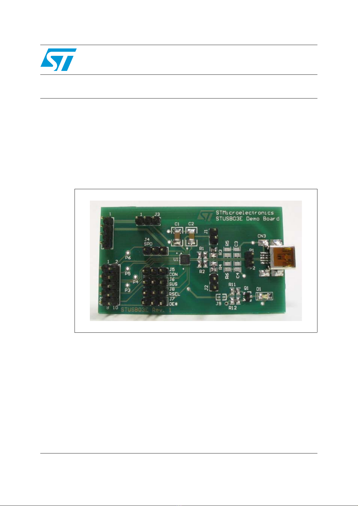
1.2 Jumper assignments
Table 1 describes the jumper assignments of the demo board.
1.3 Connector assignments
Table 1. Demo board jumper assignments
Jumper Related
pin(s) Description
J1 D+
Connected: Connects a 1.5kΩ pull-up resistor to the D+ data line. Must be
connected in Full-Speed mode when RSEL = 0
Leave Open when in Low-speed mode.
J2 D-
Connected: Connects a 1.5kΩ pull-up resistor to the D- data line. Must be
connected in Low-speed mode.
Leave Open when in Full-speed mode.
J3 VBUS
1-2 Connected: Selects CN1 connector as 5V VBUS voltage source.
2-3 Connected: 5V VBUS voltage is supplied by CN3 USB connector
J4 SPD 1-2 Connected: STUSB03E transceiver in Low-speed mode(1)
2-3 Connected: STUSB03E transceiver in Full-speed mode
1. Leave this jumper open when controlling this function using an external USB controller connected to CN2.
J5
CON,
RSEL,
SPD, VPU
1-2 Connected: VPU pin in high impedance; data line pull-up resistor
disconnected(1)
2-3 Connected: VPU pin outputs 3.3V ±10% (data line pull-up resistor
connected to internal LDO regulator output) when SPD = 1 and RSEL = 0 or
when SPD = 0
J6 SUS 1-2 Connected: STUSB03E transceiver active(1)
2-3 Connected: STUSB03E transceiver in Suspend mode
J7 OE# 1-2 Connected: STUSB03E transceiver in Transmit mode(1)
2-3 Connected: STUSB03E transceiver in Receive mode
J8 RSEL 1-2 Connected: Internal FS pull-up resistor disabled
2-3 Connected: Internal FS pull-up resistor enabled
J9 VBUSDET
Connected: Enables the VBUS voltage detection LED. LED switches ON
when voltage greater than the VBUSDET threshold is detected.
Table 2. Demo board connectors
Connector Descriptions
CN1 Power supply: VBUS, VIF and GND. Refer toTa bl e 3 for pin assignments.
CN2 Header connector for USB controller connection. Refer to Ta ble 4 for USB
controller connections.
CN3 USB mini-B connector.