UM0547 Evaluation board description
Doc ID 14682 Rev 2 5/13
2 Evaluation board description
The PTB801DC is a valve drivers board for ABS system based on STMicroelectronics
devices. The board implements a flexible and open design demonstrating the capability of
the STMicroelectronics for ABS applications. The PTB801DC mounts two L9349 devices,
the control coming from UN24 mother board.
The board has opened connectivity to external valves.
2.1 Features
General features of this board are:
●Full evaluation and development system based on the system basis chip L9349
●Full system evaluation: integration, basic and safety functions
2.1.1 L9349 quad intelligent power low-side switch
The L9349 is a monolithic integrated quad low side driver realized in an advanced
BCDmultipower mixed technology. The device is intended to drive valves in automotive
environment.
The L9349 is a quad low-side driver with following functions:
●Quad power low side driver with 2 x 5 A and 2 x 3 A output current capability
●Low RDSON typically 200 mand 300 m@ Tj= 25 °C
●Internal output clamping structures with VFB = 50V for fast inductive load current
recirculation
●Limited output voltage slew rate for low EMI
●Protected µP compatible enable and input
●Wide operating supply voltage range 4.5 V to 32 V
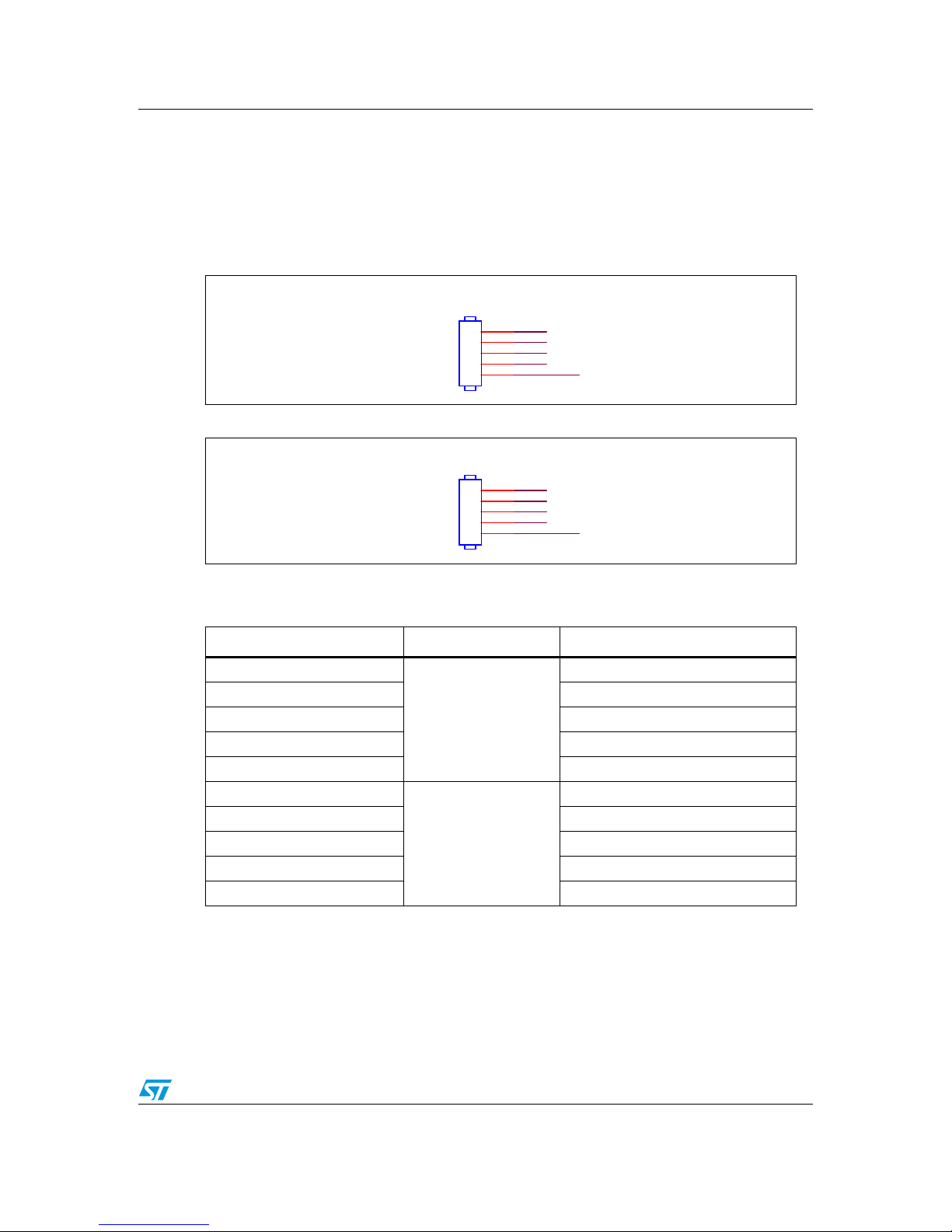
Figure 1. L9349 pin connection (top view)