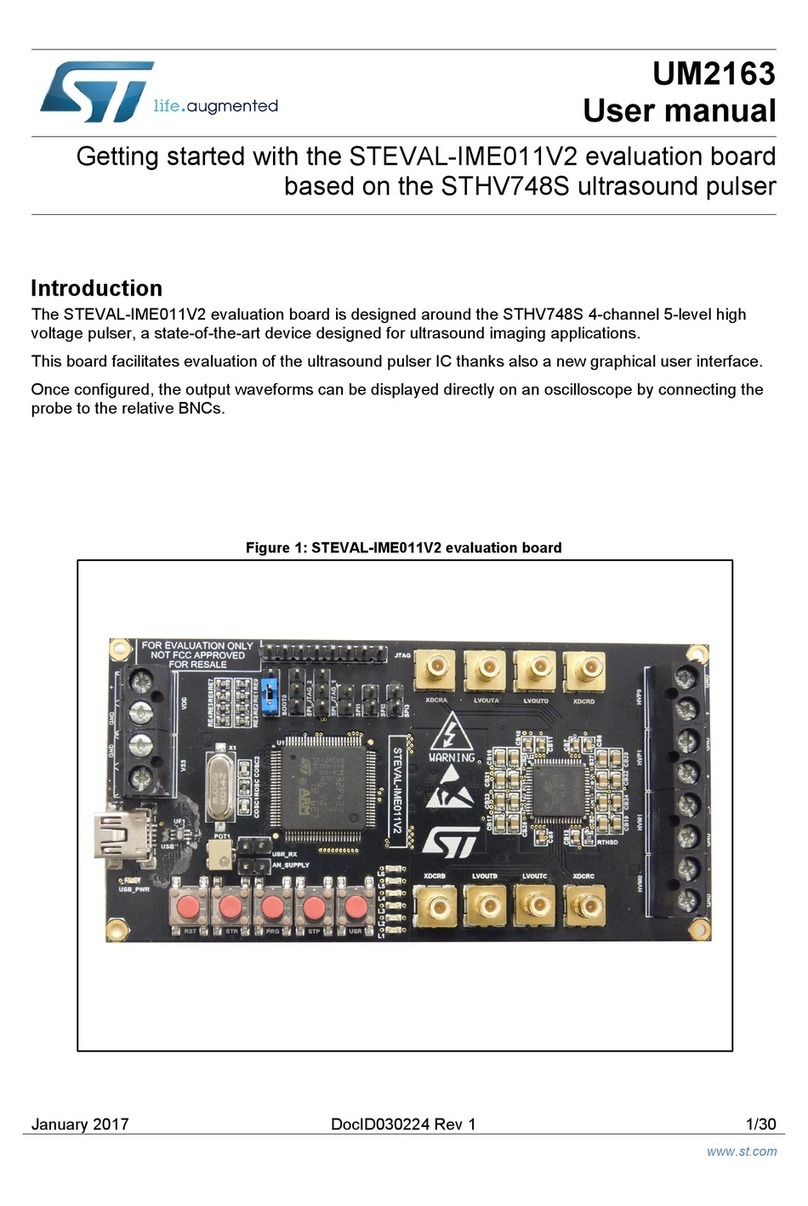
ST STEVAL-BLUEPIRV1 User manual

Introduction
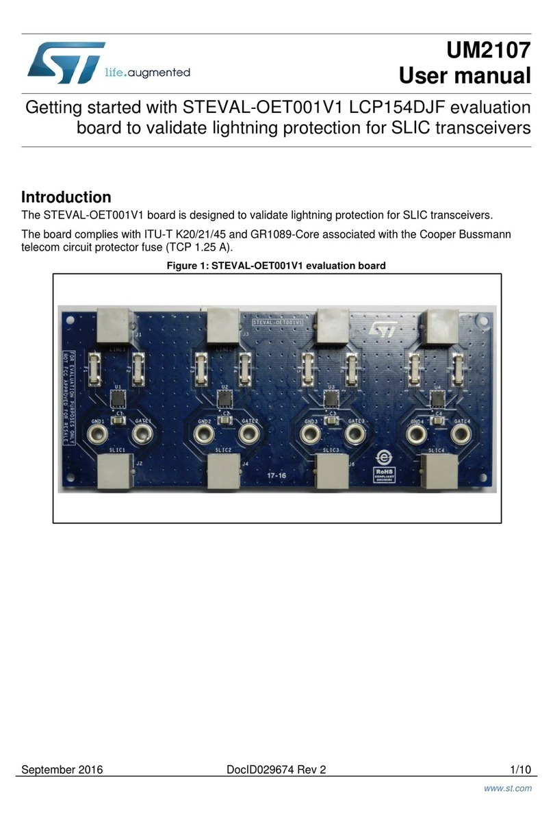
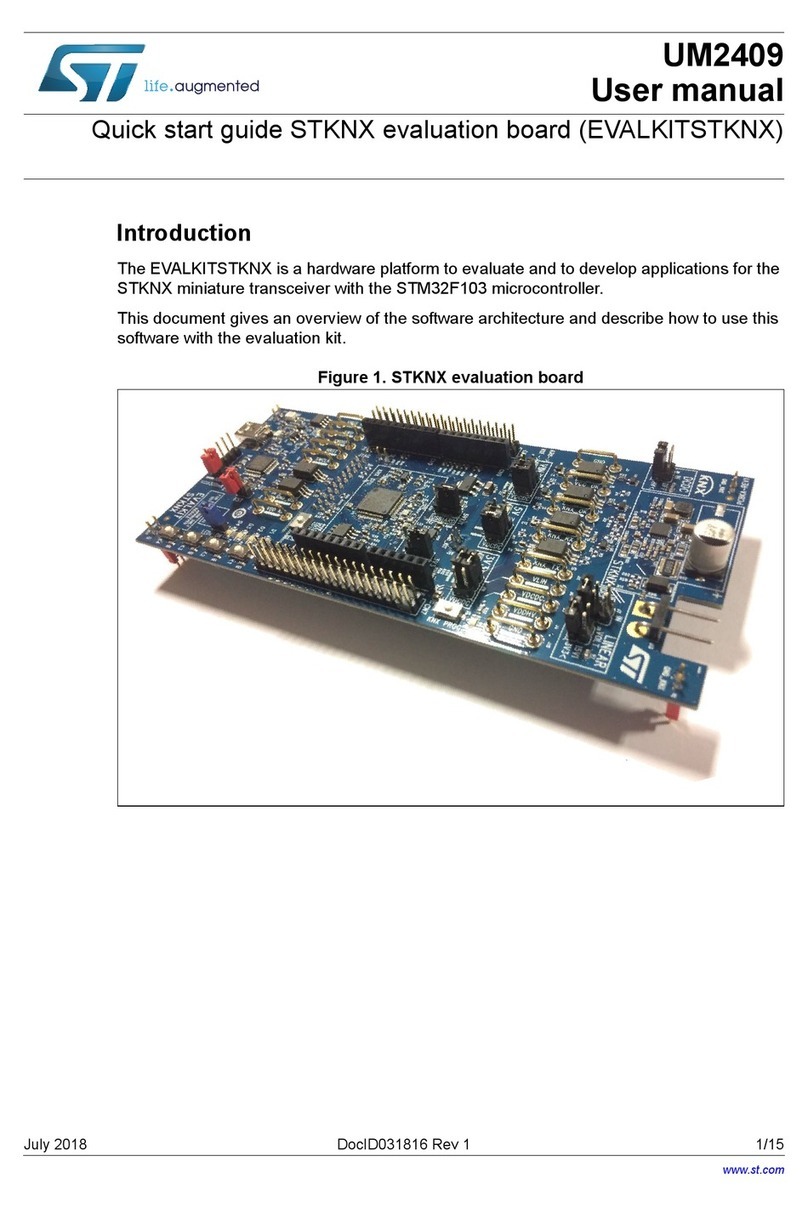
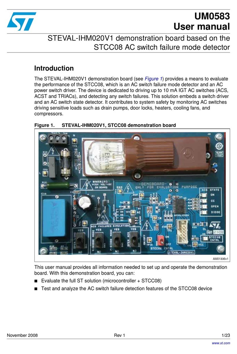
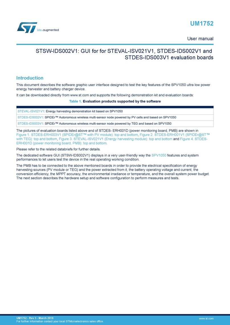
The STEVAL-BLUEPIRV1 evaluation board is an application example design of a wireless motion detector based
on a passive infrared (PIR) sensor and featuring Bluetooth® Low Energy wireless connectivity.
The passive infrared sensors are the most used sensors for motion detection, thanks to their low-power
consumption and price.
The STEVAL-BLUEPIRV1 evaluation board uses IRA-S210ST01 by Murata. The detection range of the IML-0688
Fresnel lens is up to 5 m.
The on-board low-power TSU102 CMOS op-amp and TS883 comparator perform the analog signal conditioning
with a power consumption in a sub-µA range.
The embedded BlueNRG-M2SA FCC and IC certified radio module (FCC ID: S9N-BNRGM2S and IC: 8976C-
BNRGM2SA), which integrates an application microcontroller based on an Arm®Cortex®-M0 core, features the
Bluetooth® Low Energy connectivity.
The whole design has been built by focusing on low-power consumption. Even though powered via a CR2032
coin-cell battery, the board expected lifetime is around a year.
Figure 1. STEVAL-BLUEPIRV1 evaluation board
How to use the STEVAL-BLUEPIRV1 evaluation board for Bluetooth® Low
Energy wireless motion detector based on a PIR sensor
UM3001
User manual
UM3001 - Rev 1 - April 2022
For further information contact your local STMicroelectronics sales office. www.st.com

1Overview
The STEVAL-BLUEPIRV1 evaluation board comes ready-to-use and working out-of-the-box. It provides all the
functionality expected from a wireless motion detector.
Some LEDs show the Bluetooth® Low Energy status and motion detection. Then, using the STBLESensor app,
you can visualize the battery status and signal strength as well as the motion indication.
The Bluetooth® Low Energy module is separable to allow the designer to use the analog part only.
The supply and output reading are available on a separate header and all the analog signals are placed on a
testing point.
The STEVAL-BLUEPIRV1 features:
•BlueNRG-M2SA module for Bluetooth® Low Energy communication
• Connectivity with the STBLESensor app
• Analog signal conditioning based on the TSU102 operational amplifier
• Window comparator based on the TS883 open-drain comparator
• Power management based on the STLQ020 ultra-low quiescent LDO
• Powered by a single CR2032 coin cell battery
Figure 2. STEVAL-BLUEPIRV1 block diagram
BlueNRG-M2
Cortex
M0 MCU
PCF chip
antenna
Analog signal
conditionig
PIR sensing
element
IRA-S210ST01
CR2032 Battery
Figure 3. STEVAL-BLUEPIRV1 overview (top side)
1. BlueNRG-M2SA module
2. Power management (STLQ020)
3. PIR sensor
4. Signal conditioning (TSU102)
5. Signal conditioning (TS883)
6. Motion LED
7. Bluetooth® Low Energy status LED
8. SWD connector
1
876
5
2
43
UM3001
Overview
UM3001 - Rev 1 page 2/17

2Getting started
To use the STEVAL-BLUEPIRV1, you just need to insert the battery and download the STBLESensor app on your
smartphone.
2.1 Battery
The STEVAL-BLUEPIRV1 is powered through a CR2032 coin cell battery.
Insert the battery into the holder placed at the board bottom.
Important: Use CR2032 lithium 3 V batteries only. Insert the battery with the positive (+) terminal facing out.
Caution: Risk of fire or explosion if the battery is replaced by an incorrect type or if the battery polarity is inverted. Use
only IEC 62133 certified CR2032 batteries.
Figure 4. STEVAL-BLUEPIRV1 battery insertion
2.2 Indication LEDs
There are two indication LEDs available on the board. The orange LED indicates the movement whereas the blue
LED indicates the connection over Bluetooth® Low Energy.
The orange LED lights up right after the battery is inserted. It takes around 10 seconds to stabilize the analog
circuitry and perform the proper movement indication. The orange LED is switched off shortly after the movement
stops.
The blue LED periodically blinks only when the Bluetooth® Low Energy connection is set up.
UM3001
Getting started
UM3001 - Rev 1 page 3/17

2.3 STBLESensor application
The STBLESensor application shows the data exported by a Bluetooth® Low Energy device using the BlueST
protocol.
The app shows various panels with the application data. It is available at Google Play and App Store.
Figure 5. STBLESensor app QR codes
When the device scanning is performed with the STEVAL-BLUEPIRV1 active in the smartphone range, the board
should appear in the list as BluePIR.
Figure 6. Device list
By clicking on BluePIR, the smartphone connects to the STEVAL-BLUEPIRV1. The user interface with board
information then appears.
There are two panels available when successfully connected to STEVAL-BLUEPIRV1.
UM3001
STBLESensor application
UM3001 - Rev 1 page 4/17

The first panel with the LED indicates the movement. There is a small delay before the LED switches off to
prevent flickering.
Figure 7. LED switch panel
The other panel shows the Bluetooth® Low Energy Mac address, the signal strength, and the battery voltage with
the rough state of charge information.
Figure 8. Battery status panel
UM3001
STBLESensor application
UM3001 - Rev 1 page 5/17

3Firmware
The evaluation board comes flashed with a firmware based on the STSW-BLUENRG1-DK. This software package
contains several project examples, such as the BLE_SensorDemo_BlueMSapp with few modifications:
• low-power mode selected to achieve sub µA power consumption when idle
• Bluetooth® Low Energy messages modified to show only the LED panel in the STBLEsensor app
• ADC to measure the battery voltage
You can modify the firmware according to your needs. Then, load it into the BlueNRG-M2SA module via the SWD
available on the board and use the STSW-BNRG1STLINK software package.
Note: The Bluetooth® Low Energy module is used in low-power mode and the SWD peripheral is disabled. The
STSW-BNRG1STLINK is able to connect only after the device reset.
UM3001
Firmware
UM3001 - Rev 1 page 6/17

4Schematic diagrams
Figure 9. STEVAL-BLUEPIRV1 circuit schematic
R4
1M2 C4
10n
V+
V-
3
2
1
4
8
U1A
TSU102IST
5
6
7
U1B
TSU102IST
V+
V-
3
2
1
4
8
U2A
TS883IST
5
6
7
U2B
TS883IST
D1
1N4148
R1
1R
C1
10u
R2
47k
R3
22k
C2
1n
C3
22u
C5
22u
R5
22k
R6
1M2
C7
10n
C6
10n
R7
680k
R8
390k
R9
390k
R10
680k
GND
2V5
DRAIN
SRC
GND
GND GND GND GND
2V5
GND
GND
2V5
GND
2V5
GND
R11
680k
2V5
DRAIN 1
SRC 2
GND 3
U3
PIR sensor
C8
22n
C9
22n
GNDGND
2V52V5
ADC2 1
ADC1 2
DIO4
3
DIO5
4
VIN 5
ANATEST0 / DIO14 6
DIO7 / BOOT
7
GND 8
DIO6
9
DIO8
10
DIO11
11
DIO9
12
DIO10
13 ANATEST1 14
DIO0
15
DIO2
16
DIO3
17
DIO1
18
/RESET 19
DIO12
20
GND 21
NC 22
NC 23
U4
BLUENRG-M2SA
1 2
3 4
5 6
7 8
9 10
CN3
Header 2x5
-
+
+
CN1
CR2032 Holder
VCC
GND
GND
GND
VCC
VCC
OUTOUT
OUT
LED2
R13
1k
R12
1k
GND
SWD_CLK
SWD_IO
1
2
3
CN2
Header 3
UART_TXD
UART_RXD
VCC
GND
GND
GND
GND
SWD_IO
SWD_CLK
UART_TXD
UART_RXD
RESETn
1
2
3
4
5
CN4
Header 5
VCC
SWD_CLK
GND
SWD_IO
RESETn
C13
10u
VCC
GND
C11
10n
R15
47k
VCC
GND
RESETn
R16
0R
C12
10u
2V5
GND
C10
100n
GND
LED1
VCC
C14
1u
GND GND GND
R17
2M2
R18
1M
C15
1u
GND
GND
2V5
VCC
L1
1000R Vout 1
ADJ/NC 2
GND 3
EN
4
NC
5
VIN
6
EP
7
U5 STLQ020PUR
TP1
TP2
TP3
IML-0688
Fresnel
lens
M1
UM3001 - Rev 1 page 7/17
UM3001
Schematic diagrams

5Bill of materials
Table 1. STEVAL-BLUEPIRV1 bill of materials
Item Q.ty Ref. Value Description Manufacturer Order code
1 1 CN2 N.A. Header 3, HDR1X3
Header, 3-Pin,
2.54 mm (not
assembled)
- -
2 1 CN4 N.A. Header 5, HDR1X5
Header, 5-Pin,
2.54 mm (not
assembled)
- -
3 1 U1 TSU102IST,
MiniSO-8
Nanopower
(580 nA) rail-
to-rail I/O 5 V
CMOS op-
amp
ST TSU102IST
4 1 U2 TS883IST,
MiniSO-8
Rail-to-rail 0.9
V nanopower,
open drain
dual
comparators
ST TS883IST
5 1 U5 STLQ020PUR,
DFN6 2x2
200 mA ultra-
low quiescent
current LDO
ST STLQ020PUR
6 1 CN3 N.A.
Header 2x5,
Header 2x5 1.27
SMD
Header 2x5
1.27 SMD Harwin M50-3600542R
7 1 U3 PIR sensor IRA-
S210ST01 Murata IRA-S210ST01
8 4 C4, C6, C7,
C11
10n, 0603_C, 50 V,
5 % 5%, 50V, C0G Murata GRM1885C1H103JA01
D
9 1 C2 1n, 0603_C, 50 V,
5 % 5%, 50V, C0G Murata GRM1885C1H102JA01
D
10 2 C8, C9 22n, 0603_C, 50 V,
10 %
10%, 50V,
X7R Murata GRM188R72A223KAC4
D
11 1 C10 100n, 0603_C, 50
V, 10 %,
10%, 50V,
X7R Murata GRM188R72A104KA35
D
12 3 C1, C12, C13 10u, 0603_C, 10 V,
20 %
10V, X5R,
20% Murata GRM188R60J106ME47
D
13 2 C14, C15 1u, 0603_C, 10 V,
20 %
10V, X5R,
20% Murata GRM188R60J105MA36
D
14 2 C3, C5 22u, 0603_C, 10 V,
20 %
10V, X5R,
20% Murata GRM188C80J226ME15
D
15 1 R16 0R, 0805_R, 50 V,
1 %
1%, 50V,
100mW,
+-100ppm/K
Vishay / Dale CRCW08050000Z0EA
16 3 R7, R10, R11 680k, 0603_R, 50
V, 1 %
1%, 50V,
100mW,
+-100ppm/K
Vishay / Dale CRCW0603680KFKEA
17 2 R8, R9 390k, 0603_R, 50
V, 1 %,
1%, 50V,
100mW,
+-100ppm/K
Vishay / Dale CRCW0603390KFKEA
18 2 R2, R15 47k, 0603_R, 50 V,
1 %
1%, 50V,
100mW,
+-100ppm/K
Vishay / Dale CRCW060347K0FKEA
UM3001
Bill of materials
UM3001 - Rev 1 page 8/17
Item Q.ty Ref. Value Description Manufacturer Order code
19 2 R3, R5 22k, 0603_R, 50 V,
1 %
1%, 50V,
100mW,
+-100ppm/K
Vishay / Dale CRCW060322K0FKEA
20 1 R13 1k, 0805_R, 50 V,
1 %
1%, 50V,
100mW,
+-100ppm/K
Vishay / Dale CRCW08051K00FKEA
21 1 R17 2M2, 0603_R, 50
V, 1 %
1%, 50V,
100mW,
+-100ppm/K
Vishay / Dale CRCW06032M20FKEA
22 1 R1 1R, 0603_R, 50 V,
1 %
1%, 50V,
100mW,
+-100ppm/K
Vishay / Dale CRCW06031R00FKEA
23 2 R4, R6 1M2, 0603_R, 50
V, 1 %
1%, 50V,
100mW,
+-100ppm/K
Vishay / Dale CRCW06031M20FKEA
24 1 R18 1M, 0603_R, 50 V,
1 %
1%, 50V,
100mW,
+-100ppm/K
Vishay / Dale CRCW06031M00FKEA
25 1 R12 1k, 0603_R, 50 V,
1 %
1%, 50V,
100mW,
+-100ppm/K
Vishay / Dale CRCW06031K00FKEA
26 1 U4
BLUENRG-MS2A,
BLUENRG-2
MODULE QFN,
CHIP ANT
BLUENRG-2
module ST BLUENRG-M2SA
27 1 L1 1000R, 0603_R, 1
A, 25 % Ferrite bead Murata BLM18KG102SZ1D
28 1 CN1 CR2032 holder
Battery
CR2032
holder
Linx BAT-HLD-001
29 1 LED1
LED_ORANGE,
0805_LED, 1.85 V,
2m A
LED Orange Kingbright APTD2012LSYCK
30 1 LED2
LED_BLUE,
0805_LED, 2.65 V,
2m A
LED Blue low
Vf Kingbright APTD2012LQBC/D
31 1 D1 1N4148, SOD-323,
75 V, 150m A 1N4148WS Diodes Inc 1N4148WS-7-F
32 1 M1
IML-0688, Plastic
lens R10.2 x 8.5
mm
Fresnel lens Murata IML-0688
UM3001
Bill of materials
UM3001 - Rev 1 page 9/17

6Board versions
Table 2. STEVAL-BLUEPIRV1 versions
PCB version Schematic diagrams Bill of materials
STEVAL$BLUEPIRV1A (1) STEVAL$BLUEPIRV1A schematic diagrams STEVAL$BLUEPIRV1A bill of materials
1. This code identifies the STEVAL-BLUEPIRV1 evaluation board first version. It is printed on the board PCB.
UM3001
Board versions
UM3001 - Rev 1 page 10/17

7Regulatory compliance information
Formal Notice Required by the U.S. Federal Communications Commission
FCC NOTICE
This kit is designed to allow:
(1) Product developers to evaluate electronic components, circuitry, or software associated with the kit to
determine
whether to incorporate such items in a finished product and
(2) Software developers to write software applications for use with the end product.
This kit is not a finished product and when assembled may not be resold or otherwise marketed unless all
required FCC equipment authorizations are first obtained. Operation is subject to the condition that this product
not cause harmful interference to licensed radio stations and that this product accept harmful interference. Unless
the assembled kit is designed to operate under part 15, part 18 or part 95 of this chapter, the operator of the kit
must operate under the authority of an FCC license holder or must secure an experimental authorization under
part 5 of this chapter 3.1.2.
The evaluation kit has been designed to comply with part 15 of the FCC Technical Rules. Operation is subject to
the following two conditions: (1) This device may not cause harmful interference, and (2) this device must accept
any interference received, including interference that may cause undesired operation.
This equipment has been tested and found to comply with the limits for a Class B digital device, pursuant to part
15 of the FCC Rules. These limits are designed to provide reasonable protection against harmful interference
in a residential installation. This equipment generates, uses and can radiate radio frequency energy and, if not
installed and used in accordance with the instructions, may cause harmful interference to radio communications.
However, there is no guarantee that interference will not occur in a particular installation.
Standards applied: FCC CFR 47 Part 15 Subpart B (test method applied: ANSI C63.4 v2014), FCC 47 CFR Part
15 Subpart C, §15.209 (test method applied: ANSI C63.10 v2013).
Formal Product Notice Required by Industry Canada Innovation, Science and Economic Development
Canada compliance:
For evaluation purposes only. This kit generates, uses, and can radiate radio frequency energy and has not been
tested for compliance with the limits of computing devices pursuant to Industry Canada (IC) rules.
À des fins d'évaluation uniquement. Ce kit génère, utilise et peut émettre de l'énergie radiofréquence et n'a pas
été testé pour sa conformité aux limites des appareils informatiques conformément aux règles d'Industrie Canada
(IC).
This device has been tested with Innovation, Science and Economic Development RSS standards. Operation is
subject to the following two conditions: (1) this device may not cause harmful interference, and (2) this device
must accept any interference received, including interference that may cause undesired operation.
Standard applied: ICES-003 Issue 7 (2020), Class B. Test method applied: ANSI C63.4 (2014).
Cet appareil a été testé pour les normes RSS d'Innovation, Science et Développement économique. L'utilisation
est soumise aux deux conditions suivantes: (1) cet appareil ne doit pas causer d'interférences nuisibles, et (2)
cet appareil doit accepter de recevoir tous les types d’interférence, y comprises les interférences susceptibles
d'entraîner un fonctionnement indésirable.
Norme appliquée: NMB-003, 7e édition (2020), Classe B. Méthode d'essai appliquée: ANSI C63.4 (2014).
Formal product notice required by EU
The kit STEVAL-BLUEPIRV1 is in conformity with the essential requirements of the Directive 2014/53/EU (RED)
and of the Directive 2015/863/EU (RoHS). Harmonized standards applied are listed in the EU Declaration of
Conformity.
Notice for Japan
当該機器には電波法に基づく、技術基準適合証明等を受けた特定無線設備を装着している。
(This equipment contains specified radio equipment that has been certified to the Technical Regulation Conformity
Certification under the Radio Law.)
Construction design certification number: 006-000725 (dated May 13th, 1st year of Reiwa)
UM3001
Regulatory compliance information
UM3001 - Rev 1 page 11/17

Model or name of specific radio equipment: BLUENRG-M2SA
Radio type: F1D
Frequency bands:
F1D: 2402 to 2480 MHz (2MHz bandwidth, 40 channels)
RF power:
F1D: 0.0055 W
Antenna: chip antenna with an output power of +8dBm
UM3001
Regulatory compliance information
UM3001 - Rev 1 page 12/17

Revision history
Table 3. Document revision history
Date Revision Changes
11-Apr-2022 1 Initial release.
UM3001
UM3001 - Rev 1 page 13/17

Contents
1Overview ..........................................................................2
2Getting started ....................................................................3
2.1 Battery .......................................................................3
2.2 Indication LEDs ................................................................3
2.3 STBLESensor application .......................................................4
3Firmware ..........................................................................6
4Schematic diagrams ...............................................................7
5Bill of materials....................................................................8
6Board versions ...................................................................10
7Regulatory compliance information ...............................................11
Revision history .......................................................................13
List of tables ..........................................................................15
List of figures..........................................................................16
UM3001
Contents
UM3001 - Rev 1 page 14/17

List of tables
Table 1. STEVAL-BLUEPIRV1 bill of materials ......................................................8
Table 2. STEVAL-BLUEPIRV1 versions ......................................................... 10
Table 3. Document revision history ............................................................. 13
UM3001
List of tables
UM3001 - Rev 1 page 15/17

List of figures
Figure 1. STEVAL-BLUEPIRV1 evaluation board ...................................................1
Figure 2. STEVAL-BLUEPIRV1 block diagram .....................................................2
Figure 3. STEVAL-BLUEPIRV1 overview (top side)..................................................2
Figure 4. STEVAL-BLUEPIRV1 battery insertion....................................................3
Figure 5. STBLESensor app QR codes ..........................................................4
Figure 6. Device list .......................................................................4
Figure 7. LED switch panel ..................................................................5
Figure 8. Battery status panel ................................................................5
Figure 9. STEVAL-BLUEPIRV1 circuit schematic ...................................................7
UM3001
List of figures
UM3001 - Rev 1 page 16/17

IMPORTANT NOTICE – READ CAREFULLY
STMicroelectronics NV and its subsidiaries (“ST”) reserve the right to make changes, corrections, enhancements, modifications, and improvements to ST
products and/or to this document at any time without notice. Purchasers should obtain the latest relevant information on ST products before placing orders. ST
products are sold pursuant to ST’s terms and conditions of sale in place at the time of order acknowledgment.
Purchasers are solely responsible for the choice, selection, and use of ST products and ST assumes no liability for application assistance or the design of
purchasers’ products.
No license, express or implied, to any intellectual property right is granted by ST herein.
Resale of ST products with provisions different from the information set forth herein shall void any warranty granted by ST for such product.
ST and the ST logo are trademarks of ST. For additional information about ST trademarks, refer to www.st.com/trademarks. All other product or service names
are the property of their respective owners.
Information in this document supersedes and replaces information previously supplied in any prior versions of this document.
© 2022 STMicroelectronics – All rights reserved
UM3001
UM3001 - Rev 1 page 17/17
Table of contents
Other ST Motherboard manuals

ST
ST STEVAL-IPE005V1 User manual

ST
ST STEVAL-1PS03A User manual

ST
ST SPC572L-DISP User manual

ST
ST STM8L101-EVAL User manual

ST
ST X-NUCLEO-IKS01A1 User manual

ST
ST UM1789 User manual

ST
ST STEVAL-TSP009V2 Administrator Guide

ST
ST EVAL-L99H02XP User manual

ST
ST SPC58XXADPT176S User manual

ST
ST EVAL-L9963E-MCU User manual

ST
ST STM3241G-EVAL User manual

ST
ST NUCLEO-WL55JC STM32WL User manual

ST
ST SPC56B-DIS User manual

ST
ST AEK-POW-LDOV01J User manual

ST
ST STM32H735G-DK User manual

ST
ST ST9 Series User manual

ST
ST SPC58NHADPT386S User manual

ST
ST STM32L073Z-EVAL User manual

ST
ST STM32H7 Nucleo-144 User manual

ST
ST STSW-S2LP-KNX-DK User manual