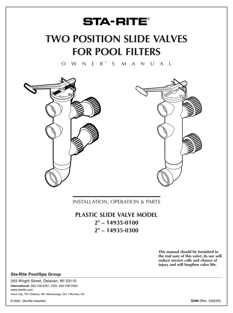
STA-RITE WC212-135D User manual

TWO POSITION SLIDE VALVES
FOR POOL FILTERS
O W N E R’ S M A N U A L
INSTALLATION, OPERATION & PARTS
BRONZE VALVE MODELS PLASTIC VALVE MODEL
1-1/2" – WC212-135D 2" – WC212-134P
2" – WC212-136D
Sta-Rite Pool/Spa Group
293 Wright Street, Delavan, WI 53115
International: 262-728-5551, FAX: 262-728-7550
www.starite.com
Union City, TN • Delavan, WI • Mississauga, Ont. • Murrieta, CA
© 2005, Sta-Rite Industries S232 (Rev. 10/11/05)
This manual should be furnished to
the end user of this valve; its use will
reduce service calls and chance of
injury and will lengthen valve life.
2815 0497 2816 0497

2
TWO POSITION SLIDE VALVE
To avoid unneeded service calls, prevent possible injuries, and get the most
out of your filter, READ THIS MANUAL CAREFULLY!
Table of Contents
Safety Instructions ........................................................................................2
Outline Dimensions .....................................................................................3
General Information.....................................................................................3
Operation ....................................................................................................4
Maintenance ................................................................................................4
Repair Parts List ........................................................................................5-6
Performance Curves .....................................................................................7
Warranty......................................................................................................8
READ AND FOLLOW ALL
INSTRUCTIONS!
This is the safety alert symbol. When you see this symbol on your sys-
tem or in this manual, look for one of the following signal words and
be alert to the potential for personal injury.
warns about hazards that will cause death, serious personal
injury, or major property damage if ignored.
warns about hazards that can cause death, serious personal
injury, or major property damage if ignored.
warns about hazards that will or can cause minor personal
injury or property damage if ignored.
NOTICE indicates special instructions not related to hazards.
Carefully read and follow all safety instructions in this manual and on equip-
ment. Keep safety labels in good condition; replace if missing or damaged.
Incorrectly installed or tested equipment may fail, causing
severe injury or property damage.
Read and follow instructions in owner's manual when installing
and operating equipment. Have a trained pool professional per-
form all pressure tests.
1. Do not connect system to a high pressure or city water system.
2. Use equipment only in a pool or spa installation.
3. Trapped air in system can cause explosion. BE SURE all air is out of system
before operating or testing equipment.
Before pressure testing, make the following safety checks:
• Check all clamps, bolts, lids, and system accessories before testing.
• Release all air in system before testing.
• Tighten Sta-Rite trap lids to 30 ft. lbs. (4.1 kg-cm) torque for testing.
•Water pressure for test must be less than 25 PSI (172 kPa).
• Water Temperature for test must be less than 100oF. (38oC).
• Limit test to 24 hours. After test, visually check system to be sure it is ready
for operation. Remove trap lid and retighten hand tight only.
NOTICE: These parameters apply to Sta-Rite equipment only. For
non-Sta-Rite equipment, consult manufacturer.

3
OUTLINE DIMENSIONS
Model No. Size A B C D E F G H Port J Port
WC212-135D 11⁄2237⁄8181⁄87.81 1.94 6.06 5.69 6.75 11⁄2NPT 11⁄2NPT
WC212-136D 2 245⁄81813⁄16 7.81 2.44 5.85 5.75 7.31 2 NPT 2 NPT
WC212-134P 2 261⁄8201⁄27.81 3.03 6.56 5.44 8.12 2 SLIP 2 NPT
Figure 1
Sta-Rite Filters
DE Filters Sand Filters
DEP36-01 HRP20-01
DEP51-01 HRP24-01
DEP83-01 HRP30-01
DES25-01 HRS16-01
DES51-01 HRS20-01
DES60-01 HRS24-01
GENERAL
Inspect valve upon receipt and file claim with carrier if parts are damaged or
missing.
Valve may be used with Sta-Rite DE or sand filters. See Table I.
Mating half of unions are on filters shown on Table I.
TABLE I

4
OPERATION
Valves are two position valves. Valve handle must be fully extended or fully
depressed. There is no in between, or throttling position. Connect center
port to pump.
With valve stem depressed, (Figure 2), pump water is directed to bottom
filter port. Top filter port is open to upper discharge. Lower discharge is idle.
With valve stem extended, (Figure 3), pump water is directed to top filter
port. Bottom port is open to lower discharge.
MAINTENANCE
Filter Control Valve (Slide Valve):
Turn Pump OFF Before Proceeding.
1. Inspect bi-yearly. Check for ease of operation. If handle is difficult to
move, follow steps 2 through 6 below.
2. Disassemble valve:
A. Remove three screws in index plate.
B. Remove piston assembly using a straight upward pull. Rotate assem-
bly slightly for easy removal.
3. Inspect O-Ring for nicks, cuts, cracks, etc. Replace if necessary.
4. Inspect valve seating areas for grooves, nicks, etc. Remove any corrosion
by sanding with No. 400 wet or dry emery cloth, using it wet.
NOTICE: Sand lightly so as not to destroy the seating area.
5. Lubricate O-Rings with Aqua-Lube1grease or petroleum jelly, before
reassembling valve.
6. Reassemble valve:
A. Insert piston assembly into valve body.
B. Replace three screws loosely.
C. Lift the valve handle into “BACKWASH” position. This well center
the index plate with the piston shaft and valve bore.
D. Tighten three screws securely.
E. Place the piston assembly into the “FILTER” position. It should slide
easily. If not, repeat above until piston moves freely.
Winterizing For Freezing Climates:
Place valve handle in an intermediate position, between “FILTER” and
“BACKWASH” positions.
CONNECTING SLIDE VALVE
TO FILTER SYSTEM
NOTICE: Filter ports and valve ports are furnished with union connections,
matching the connections of the filter ports. DO NOT use pipe sealants on
union collar (nut).
Use care before assembly not to damage union sealing surfaces or O-Ring.
Install union O-Rings in groove; tighten union collar hand tight.
FOR SLIP FITTINGS: Use correct solvent/cement when fitting piping or
adapters to slide valve. The valve body is ABS plastic, thus any good quality
ABS to PVC solvent can be used, such as Weld-On #793 or #710. Use P-70
(purple) primer on PVC components only. Allow a minimum of four hours
drying time prior to pressure testing or operation. If ABS adapters are glued
into valve ports in lieu of PVC fittings, use Weld-On Solvent #771, #1707
or #773.
To avoid serious personal injury or property damage, follow
cement manufacturer’s instructions exactly.
FOR THREADED FITTINGS: Use Plasto-Joint Stik2only. Other substances
may degrade plastic and create poor joints and leaks.
NOTICE: Do not overtighten.
1Far Best Co., Los Angeles, CA
2Lake Chemical Co., Chicago, IL
Figure 2 – “Filter” Position.
Water flow pattern shown with
valve handle in fully depressed
position.
Figure 3 – “Backwash” Position.
Water flow pattern shown with
valve handle in fully extended
position.

5
REPAIR PARTS LIST
Plastic Valve
Model WC212-134P
2817 0497
1
2
7
5
6
10
9
8
12
14
13
11
3
4
4
• Not illustrated.
* Not sold separately.
Key Model
No. Description Qty. WC212-134P
1 Handle 1
2 Spring Pin 1 Kit #14930-0031
3 Lever Linkage 2
4 Spring Pin 2
4 Spring Pin 2
5 Index Plate (includes O-Ring)* 1 Kit #14930-0032
6 O-Ring (available Separately) 1 35505-1246
7 Lock Pin Assembly 1 WC30-84
8 Body Assembly 1 WC112-134P*
9 Union Collar 2 U11-200P
10 Union Adapter Assembly 2 U11-199P
11 O-Ring 2 U9-362
12 O-Ring** 2 Kit #14930-0033
13 Molded Piston Assembly 1
14 Screw 6 37107-0085
* Index Plate O-Ring 1 35505-1116
** O-Ring (available Separately) 2 35505-1318
}
}
}

6
REPAIR PARTS LIST
Bronze Valve
11⁄2” – WC212-135D
2” – WC212-136D
2818 0497
1
2
5
6
7
10
9
8
11
13
14
12
6
3
4
2
Key Model Model
No. Description Qty. WC212-135D WC212-136D
1 Lever Handle 1 14821-0005 14821-0005
2 Spring Pin 2 35817-0056 35817-0056
3 Spring Pin 1 35817-0061 35817-0061
4 Linkage 2 14821-0008 14821-0008
5 Lock Pin Assembly 1 WC30-84 WC30-84
6 O-Ring 3 35505-1401 35505-1313
7 Valve Body 1 WC112-135D WC112-136D
8 Union Adapter 2 38405-4089 U11-199P
9 Union Collar 2 U11-200P U11-200P
10 O-Ring 2 U9-362 U9-362
11 Piston Assembly 1 14819-0011 14823-0011
12 Index Plate 1 14821-0007 14823-0016
13 Screw 2 37062-0130 37062-0130
14 Screw 1 37062-0134 37062-0134
•15 Index Plate O-Ring 1 35505-1116 35505-1116
* Handle Replacement Kit 1 14821-0067 14824-0067
• Not illustrated.
* Includes Key Nos. 1, 2, 4, 6, 12, 13, 14 and 15.

7
Performance Curves
Five Port Quick Position Valves
NOTE: Curves represent total loss of both halves of valve (double pass thru valve).
020 40 60 80 100 120 140
00
5
10
15
20
Flow in Gallons Per Minute (Liters per Minute)
Pressure Loss in Feet (Meters)
Pressure Loss in P.S.I. (kPa)
25
2.16
4.32
6.49
8.65
2819 0497
10.81
1 1/2" Brass
2" Brass
2" Plastic
(Filter Position)
2" Plastic
(Backwash Position)
(76) (378)
(14.9)
(18.7)
(44.7)
(59.6)
(74.5)
(530)
(454)
(303)(227)
(151.4)
(1.5)
(3)
(4.6)
(6.1)
(7.6)

CREATE A RECORD OF YOUR WARRANTY AT STA-RITE:
• Complete a warranty registration at www.staritepool.com by clicking on “Register Products” and selecting Sta-Rite Pool
OR
• Complete bottom portion completely and mail within 10 days of installation to Sta-Rite, Attn.: Pool Warranty Dept., 293 Wright St., Delavan , WI 53115
Warranty Registration Card
Name
Address
City State Zip
Installation (or Purchase) Date
Product Purchased
Model Number
■■New installation ■■Replacement
Years pool has been in service ■■less than 1 ■■1-3 ■■3-5 ■■5-10
This product was purchased from:
Company name
Address
City State Zip
STA-RITE LIMITED WARRANTY
For technical information about this product, contact the installer or call Sta-Rite at 262-728-9181.
Visit www.staritepool.com
• for more information about Sta-Rite products listed above
• to locate a Sta-Rite dealer near you
Product Specific Warranties (from date of installation)
Product Limited
Family Warranty Exceptions
Filters 1 Year System 3 Tank Bodies - 10 Yrs
Filter Valves 1 Year
Pumps 1 Year
Heaters 2 Years *Commercial Application - 1 Yr
Controls 1 Year
Above Ground Systems 1 Year
Lights and Niches 1 Year Lamps and Bulbs - 90 Days
White Goods 1 Year
Maintenance Equipment 90 Days
Drainer/Utility Pumps 90 Days
Replacement Parts 90 Days
Cleaners: Lil Shark 1 Year
Cleaners: Calypso 1 Year
Cleaners: Pool Shark 2 Years Footpad and Seal Flaps - 1 Yr
Cleaners: Great White 2 Years
* Commercial and multi-family application.
Retain this warranty certificate in a
safe and convenient location for your records.
Pumps, filters, skimmers, underwater lights (excluding bulbs),
accessories and fittings manufactured by Sta-Rite are warranted
to be free of defects in material and/or workmanship for one (1)
year from the original date of installation.
The foregoing warranties relate to the original consumer purchas-
er (“Purchaser”) only. Sta-Rite Industries shall have the option to
repair or replace the defective product, at its sole discretion.
Purchasers must pay all labor and shipping charges necessary to
replace the product covered by this warranty. Requests for war-
ranty service must be made through the installing dealer. This
warranty shall not apply to any product that has been subject to
negligence, misapplication, improper installation or maintenance,
or other circumstances which are not in Sta-Rite’s direct control.
Failure to have product installed by a professional in compliance
with local codes will void any and all manufacturers warranty.
This warranty sets forth Sta-Rite’s obligation and Purchaser’s
exclusive remedy for defective products.
STA-RITE SHALL NOT BE LIABLE FOR ANY CONSEQUENTIAL,
INCIDENTAL OR CONTINGENT DAMAGES WHATSOEVER.
THE FOREGOING WARRANTIES ARE EXCLUSIVE AND IN
LIEU OF ALL OTHER EXPRESS WARRANTIES. IMPLIED
WARRANTIES, INCLUDING BUT NOT LIMITED TO THE
IMPLIED WARRANTIES OF MERCHANTABILITY AND FITNESS
FOR A PARTICULAR PURPOSE, SHALL NOT EXTEND
BEYOND THE DURATION OF THE APPLICABLE EXPRESS
WARRANTIES PROVIDED HEREIN.
Some states do not allow the exclusion or limitation of incidental
or consequential damages or limitations on how long an implied
warranty lasts, so the above limitations or exclusion may not
apply to you. This warranty gives you specific legal rights and you
may also have other rights which vary from state to state.
Supersedes all previous publications.
S4877PS (Rev. 7/21/04)
This manual suits for next models
2
Table of contents
Other STA-RITE Control Unit manuals
Popular Control Unit manuals by other brands

GEM
GEM R477 Tugela operating instructions

Sharp
Sharp JW Series Connection manual

Kessel
Kessel Comfort PLUS Instructions for installation and operation

CRU
CRU WiebeTech Ditto quick start guide

metso automation
metso automation Eliminator 9FB-3600XT Installation maintenance and operating instructions

GRAUPNER
GRAUPNER 3975 manual