STABLE GRAZER GENERATION II User manual

Generation II
Installation Guide
Caarter2 Systems, Inc
PO Box 6206
Beaverton OR 97007
1-800-732-1654
www.StableGrazer.com

2
Congratulations on your purchase of the Stable Grazer® Generation II automatic hay feeder. The
following instructions may be used as a general guide for installing the Stable Grazer® Generation II.
If you are unsure of your ability to install the Stable Grazer® Generation II you should consult a
licensed contractor. Before modifying any structure, consult with your local building inspector to be
certain of your local and state building codes.
The Stable Grazer® is very versatile and can be mounted almost anywhere. Several different
installations will be covered in this guide. Whichever installation you choose, it is recommended that
the feeder be installed in such a way that your horse can not access the door. If your only choice is to
install the feeder so your horse has access to the door, it will be necessary to install some type of
device to keep the horse from rubbing on the door area. The following installations are for reference
only. Each situation is different, therefore making it impossible to give exact information. You are
responsible for determining your own measurements.
Contents
Misc. Parts…………………………………………………………………………...Page 3
Install Handle & Remove Shipping Strap....………………………………………...Page 4
Stall Front Installation……………………………………………………………….Page 5
Wall Installation (feed through the wall)……………………………………………Page 9
Post Mount…………………………………………………………………………Page 11
Battery Installation…………………………………………………………………Page 14
Removing the Door & Strut………………………………………………………..Page 15
3
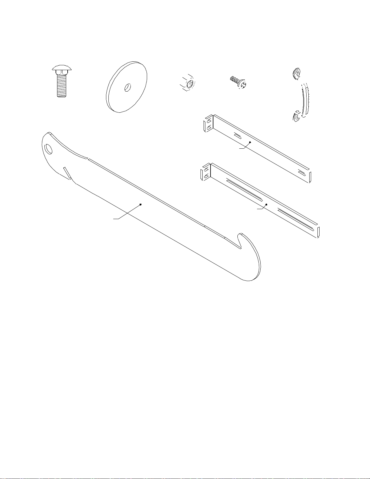
Misc. Parts
5/16 x 1
Carriage Bolt
Handle
5/16 x 2
Flat Washer
Strut Load Tool
Main Mount Bracket
Top Mount Bracket
5/16 Nut 10-32 x 1/2
Panhead Screw
The miscellaneous parts are zip tied to the manger rods. Check to make sure you received all of the following.
(4) 5/16 x 1 Carriage Bolts
(4) 5/16 x 2 Flat Washers
(4) 5/16 Hex Nuts
(2) 10-32 x ½ Phillips Panhead Screws
(1) Handle
(2) Top Mount Brackets
(2) Main Mount Brackets (These are attached to the sides of the feeder for shipping.)
(1) Strut Load Tool (Needed for removing the door or replacing the strut. Keep for future use!)
(4) “C” Cell Batteries
(1) Owners Manual
(1) Installation Guide

4
Install the Handle
Install the door handle using two 10-32 x ½” Phillips Panhead Screws. (Detail A)
Remove the shipping strap
Caution! Do not perform this step without placing a counterbalance on or in the manger.
Pull the door open. You will feel some resistance from the gas strut compressing. Loosen the two 10-32 x ½”
Phillips Panhead Screws that hold the shipping strap in place. Remove the strap by pulling it from between the
door side and door. Discard the shipping strap. Re-tighten the two 10-32 x ½” Phillips Panhead Screws.
5
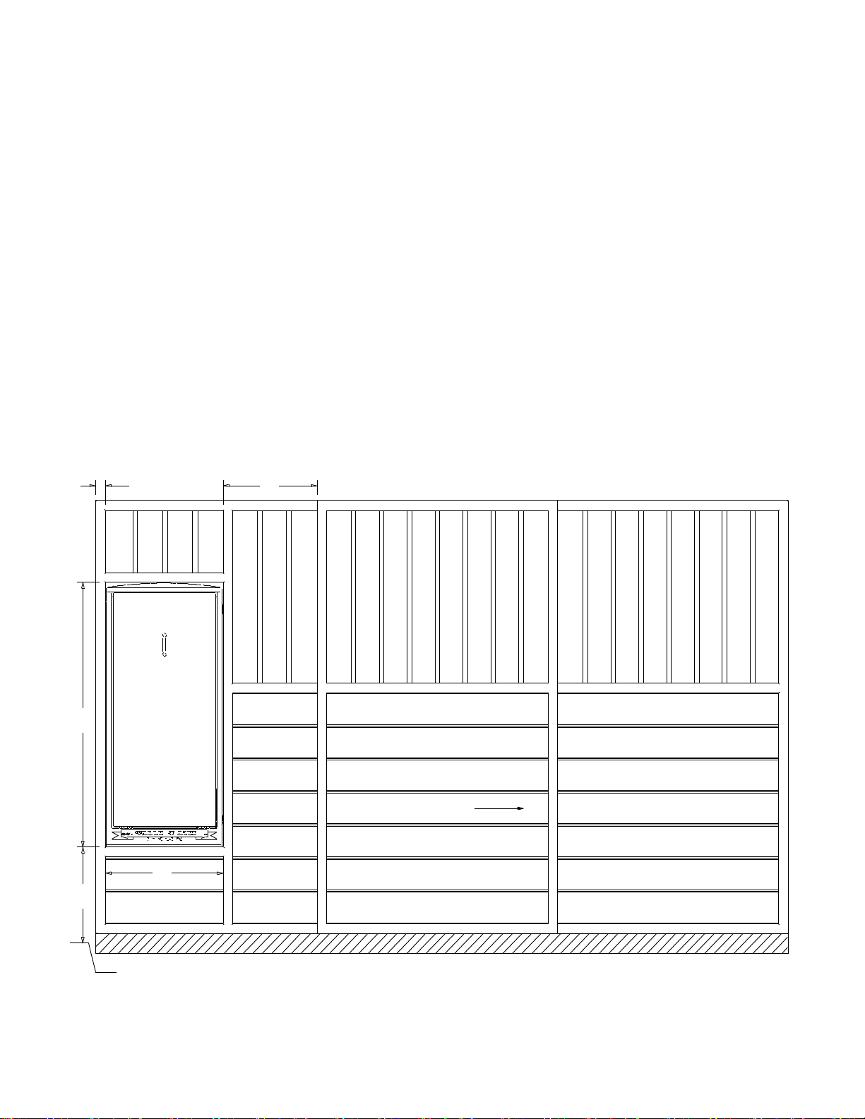
Typical Stall Front Installation
A- 20" to stall floor. Many stalls have an elevation
change between the stall and breezeway floors.
Therefore this measurement should be from the stall
floor to allow the feeder to rest on the stall floor.
B- 24-1/2"
C- 55" or more. It's not necessary to fill in the area
above the feeder. But if you do you should have a
55" opening.
D- 1-1/2" minimum. The frame on each side of the
feeder should be at least 1-1/2" for fastening the
mounting brackets.
E- When using sliding stall doors be sure to allow
enough room for the door to slide open without
hitting the feeder. IMPORTANT: This is particularly
critical when the stall door is in the center of the
stall. If this is the case the door will more than likely
have to slide away from the feeder.
D E
C
A
B
In this example the stall floor is 2" below the breezeway floor.
Breezeway Floor
Stall Door slides
away from feeder
Front View
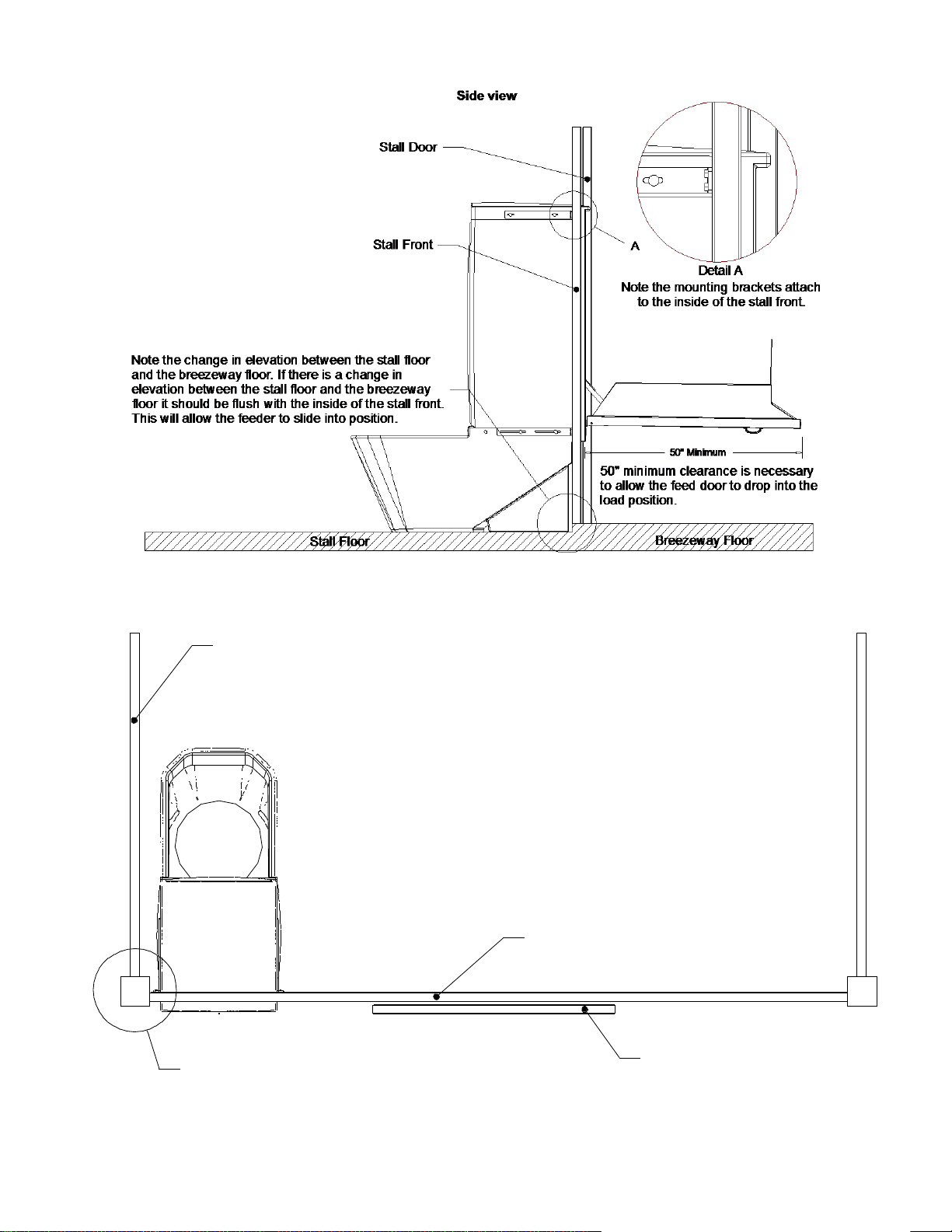
6
Stall divider or wall.
Top View
Stall Front
Stall Door
Make sure the door doesn't slide into
the feeder. If you have a center door
it will more than likely need to slide
away from the feeder.
Make sure a stall divider or post doesn't interfere with the
installation of the feeder. If you are installing the feeder close
to a stall divider it may be easier to install the feeder before
the divider.
7
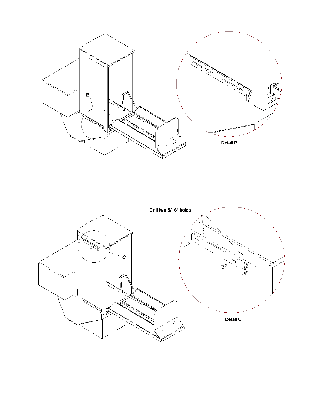
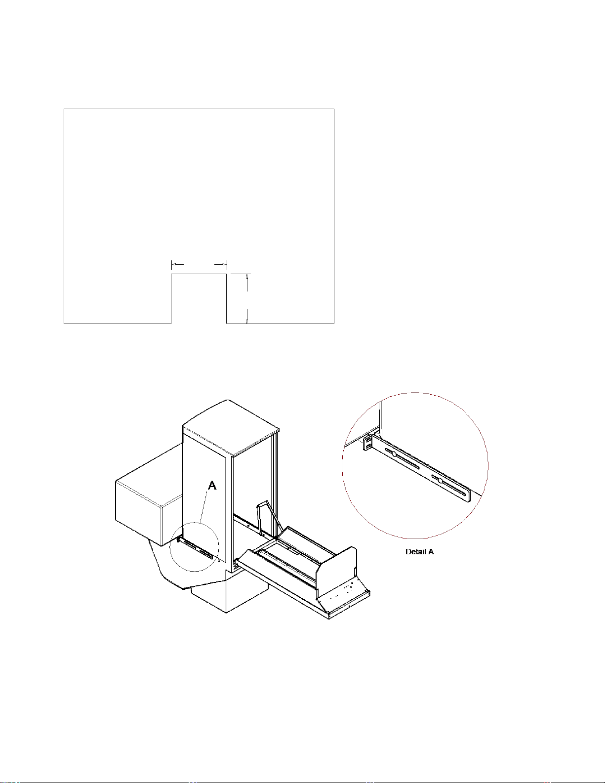
1. Caution! Do not open the door until you have placed a counterbalance on or in the manger. Pull the
door open. You will feel some resistance from the gas strut compressing. Remove the mounting bracket using a
1/2" wrench. Re-install the mounting bracket with the short leg extended away from the feeder. Place the end of
the bracket 3" from the front of the feeder as shown in Detail B. Repeat for the mounting bracket on the opposite
side. (If necessary the door may be removed for these steps. Refer to the Door & Strut Removal instructions)
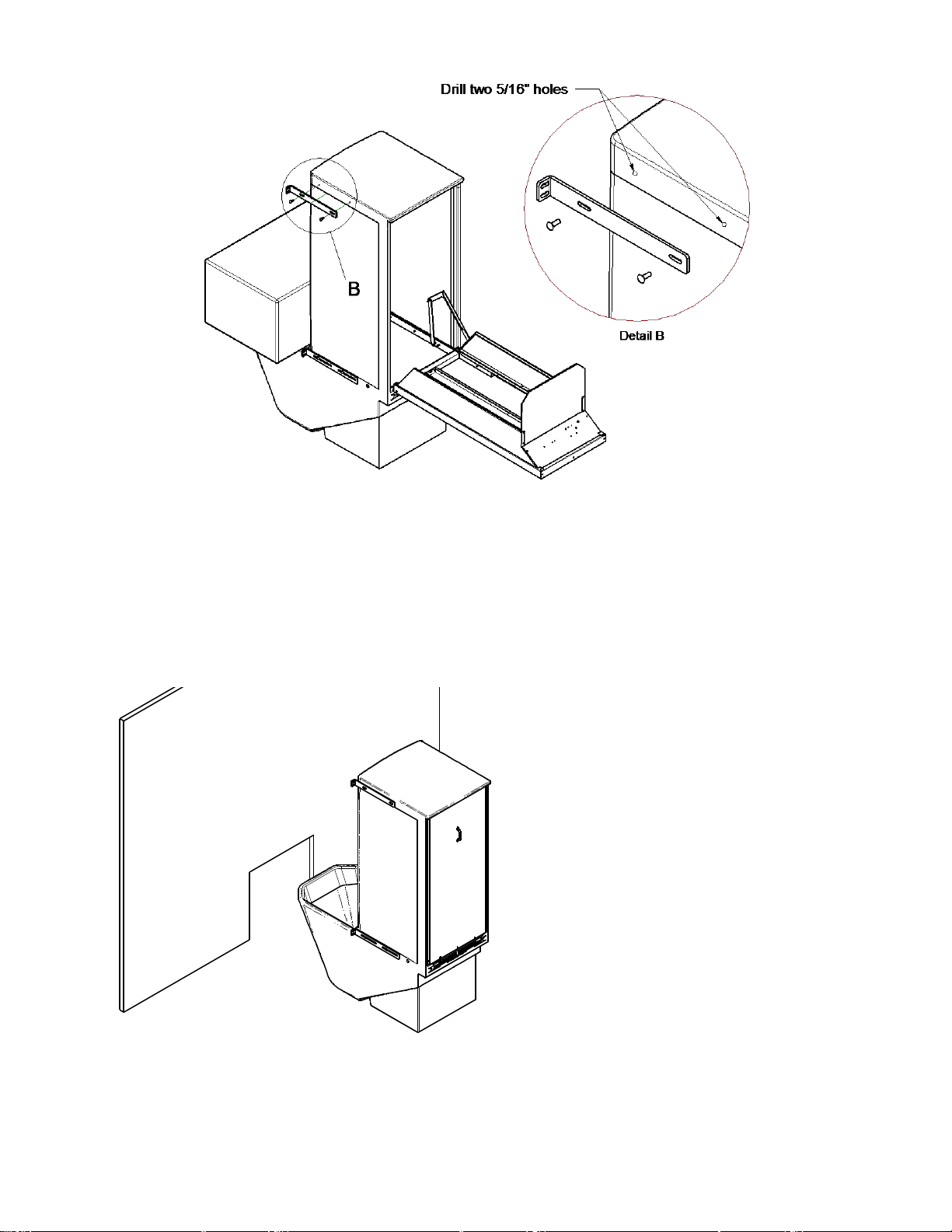
2. Place the top mounting bracket in place with the bottom edge of the bracket approximately 3" from the top of
the feeder. The short leg of the bracket should be the same distance from the front of the feeder as the brackets
installed in the previous step. Make a mark in the center of each slot and drill a 5/16" hole at each mark. Attach
the bracket with two 5/16" x 1" carriage bolts, large washers and 5/16" nuts. (included) Repeat for the top
mounting bracket on the opposite side.

8
3. Slide the feeder into position from inside the stall. Push it in until the mounting brackets come into contact
with the stall front.
5. Install fasteners (not included) in the previously drilled holes and tighten.
6. Check the alignment of the door in the opening. If necessary, loosen and adjust the brackets for proper
alignment.
9
Thru the Wall Installation
1. Locate and cut a 24 ½” x 22 ¼” hole in the
wall. This is where the horse will access the
feed manger. If your wall is more than a
couple of inches thick you may need to cut a
taller opening to allow your horse better
access to the feed manger. Be careful not to
cut any supporting structure. Depending
on the design of your wall, some
additional support may be required. If you
are not sure of the consequences of
cutting a hole in your wall, you should
consult a licensed contractor.
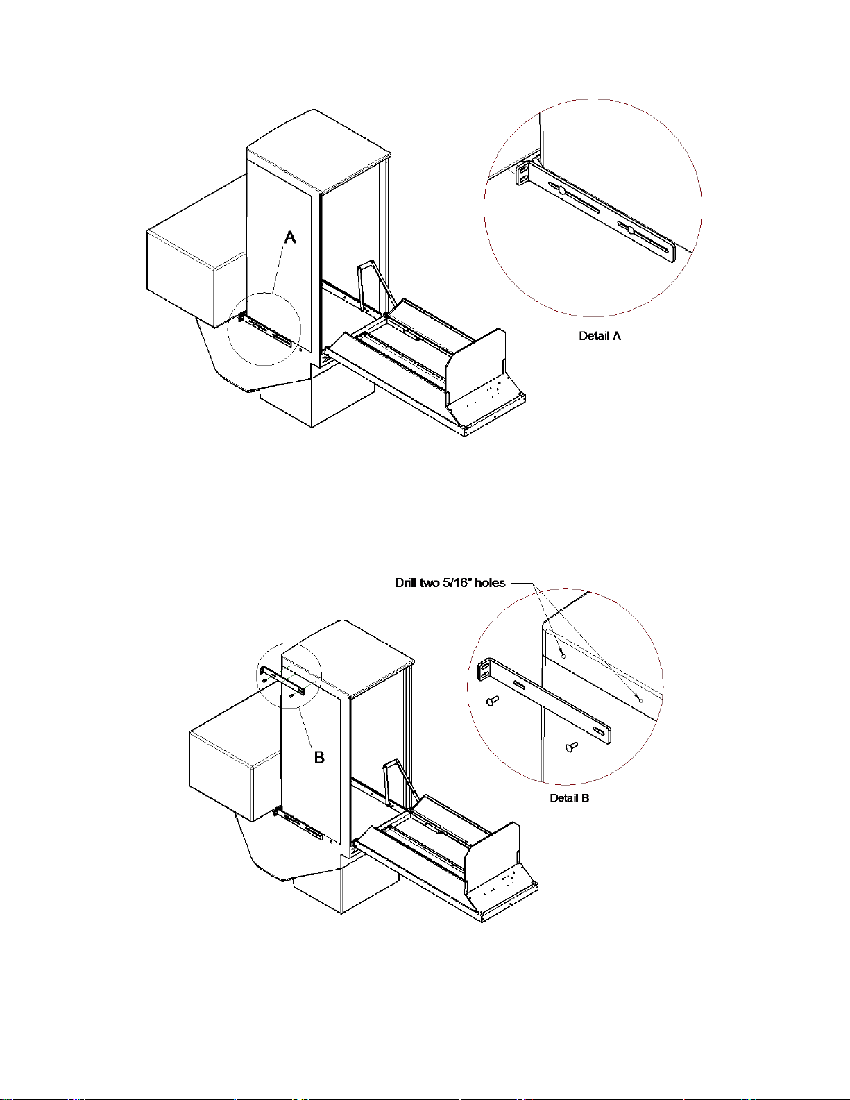
2. Caution! Do not open the door until you have placed a counterbalance on or in the manger. Pull the
door open. You will feel some resistance from the gas strut compressing. Remove the mounting bracket using a
1/2" wrench. Re-install the mounting bracket with the short leg extended away from the feeder. Place the end of
the bracket slightly past where the manger starts as shown in Detail A. Repeat for the mounting bracket on the
opposite side. (If necessary the door may be removed for these steps. Refer to the Door & Strut Removal
instructions)
22 1/4
24 1/2
10
3. Place the top mounting bracket in place with the bottom edge of the bracket approximately 3" from the top of
the feeder. The short leg of the bracket should be the same distance from the back of the feeder as the brackets
installed in the previous step. Make a mark in the center of each slot and drill a 5/16" hole at each mark. Attach
the bracket with two 5/16" x 1" carriage bolts, large washers and 5/16" nuts (included). Repeat for the top
mounting bracket on the opposite side.
4. Slide the feeder into position. Push it in until
the mounting brackets come into contact with
the wall.

11
73.0
24.5
Ground Level
4x4 Post
2x4
6. Install fasteners (not included) in the previously drilled holes and tighten.
7. Check the alignment of the door in the opening. If necessary, loosen and adjust the brackets for proper
alignment.
Mount To Post Installation
1. Bury two posts 24.5” apart with approximately 73” above ground
level. Depending on your soil type you may want to use concrete for
added stability. Attach a 2x4 across the top of the posts.
12
2. Caution! Do not open the door until you have placed a counterbalance on or in the manger. Pull the
door open. You will feel some resistance from the gas strut compressing. Remove the mounting bracket using a
1/2" wrench. Re-install the mounting bracket with the short leg extended away from the feeder. Place the end of
the bracket slightly past where the manger starts as shown in Detail A. Repeat for the mounting bracket on the
opposite side. (If necessary the door may be removed for these steps. Refer to the Door & Strut Removal
instructions)
3. Place the top mounting bracket in place with the bottom edge of the bracket approximately 3" from the top of
the feeder. The short leg of the bracket should be the same distance from the back of the feeder as the brackets
installed in the previous step. Make a mark in the center of each slot and drill a 5/16" hole at each mark. Attach
the bracket with two 5/16" x 1" carriage bolts, large washers and 5/16" nuts (included). Repeat for the top
mounting bracket on the opposite side.
13
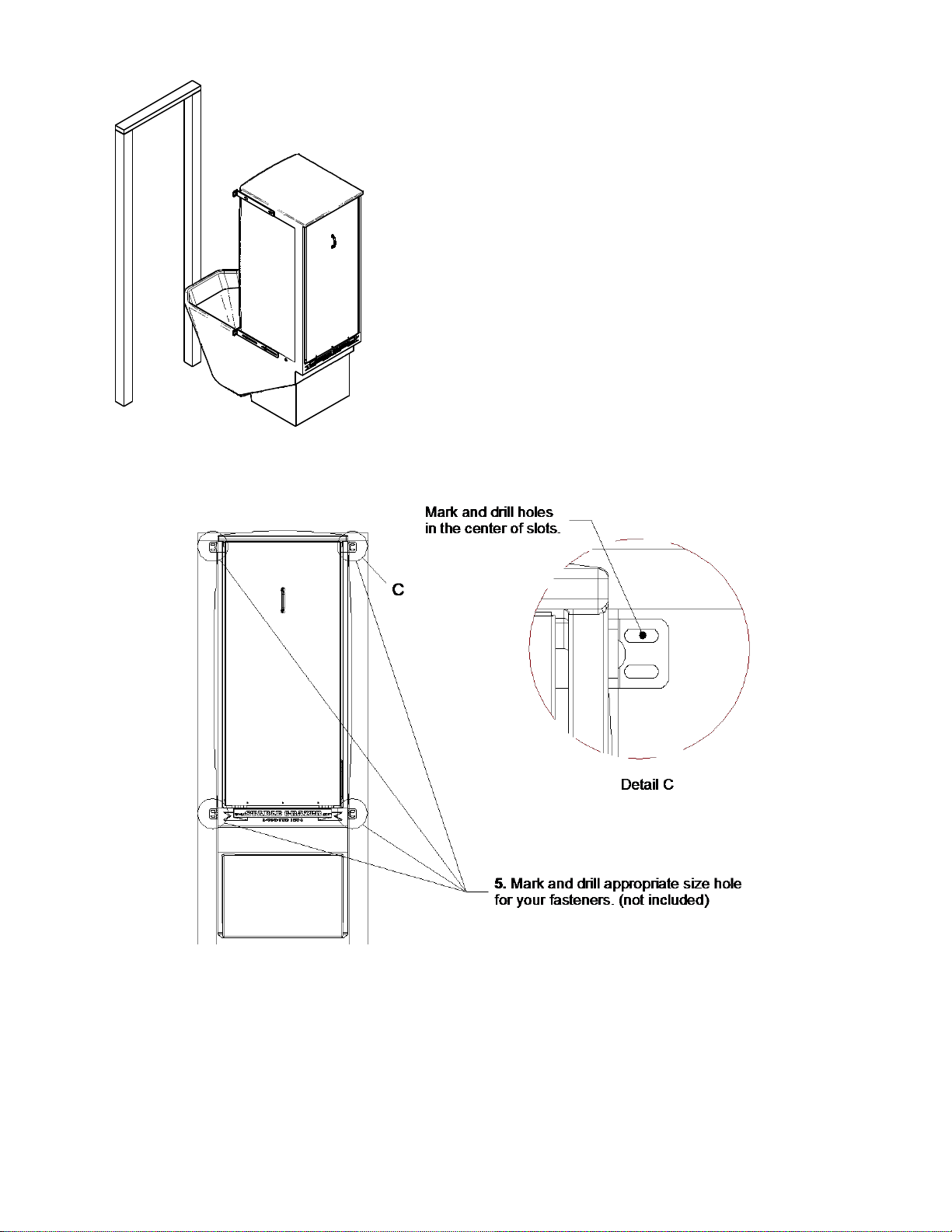
4. Slide the feeder into position. Push it in until the mounting
brackets come into contact with the posts.
6. Install fasteners (not included) in the previously drilled holes and tighten.
7. Check the alignment of the door in the opening. If necessary, loosen and adjust the brackets for proper
alignment.
14
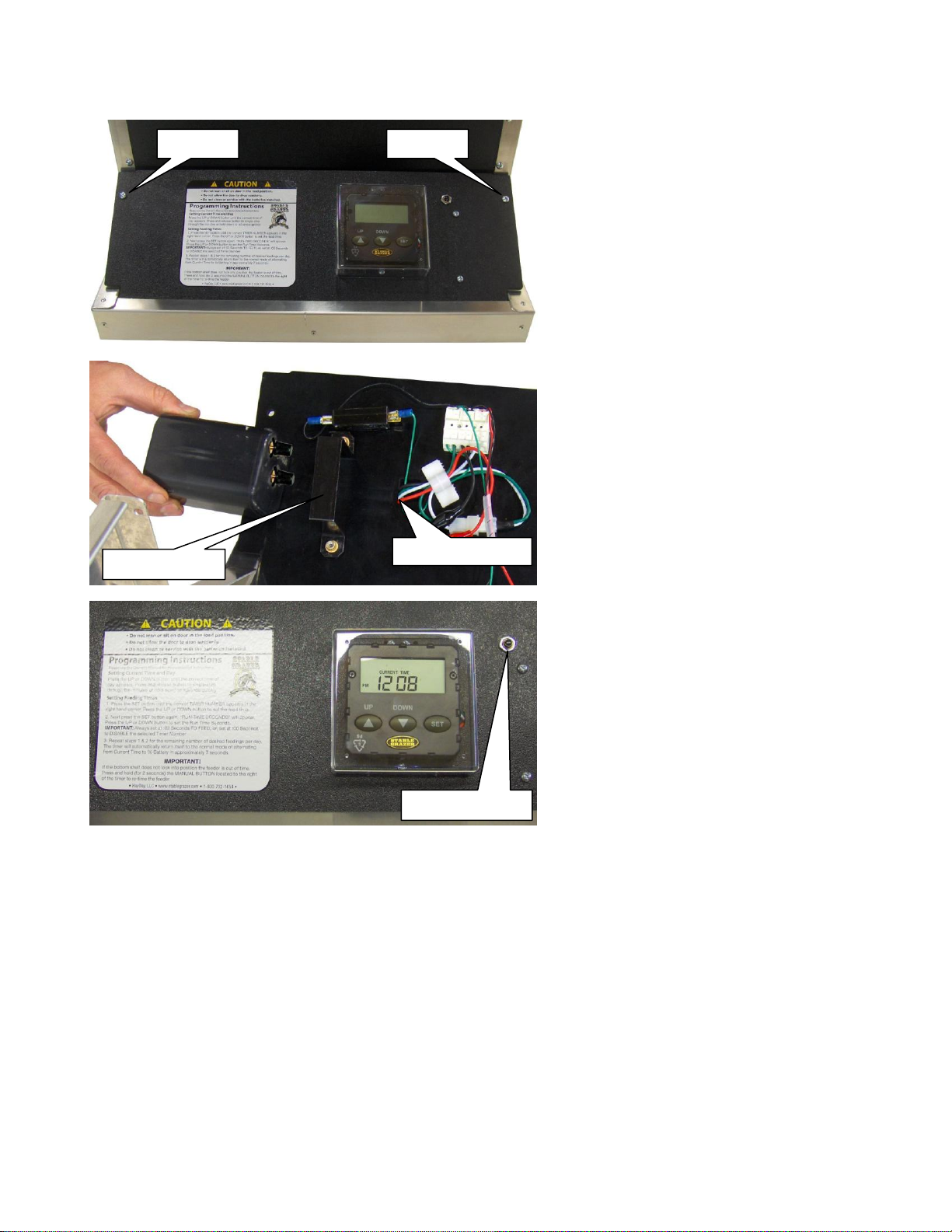
Battery Installation
1. Remove the two 10-32 screws holding the
Control Panel. Tip the Control Panel towards
you to reveal the back side.
2. Loosen the two 10-32 screws holding the
Battery Clamp until you are able slip a 6 Volt
screw terminal battery (not included) into the
Battery Clamp. Slide it in until it just touches
the wires coming through the Control Panel.
Tighten the two 10-32 screws holding the
Battery Clamp until the battery feels snug.
Attach the wires to the battery terminals.
Take special care to attach the red wire to
the positive (+) and the black wire to the
negative (-) terminals. Note: The Back Stop
is removed for clarity.
3. Test the connections by pressing the
manual switch, the camshaft should begin to
rotate. Continue to press the manual switch
for two seconds then release. The camshaft
should continue until it completes a 180˚
rotation. The camshaft should rotate in a
counter clockwise direction when looking at it
from the Control Panel end. If it rotates the
wrong direction, check the positve and
negative connections on the battery.
Your Stable Grazer Generation II Feeder is now ready to program and use. The clear friction fit timer cover can
be removed by lifting it away from the control panel. Please refer to the Owner’s Manual or the decal to the left
of the timer for programming instructions.
Remove
Remove
Slide In To Here
Manual Switch
Battery Clamp

15
Removing the Strut and Door
This is not necessary for initial setup. It is only necessary to do this if the strut needs to be replaced or the door
needs to be removed for some reason.
1. Open the door and place the slot of the strut hook
over the slide at the top of the L-linkage.
2. Lift the door enough to hook the other end of the
strut hook under the lip of the manger just below the
main frame
3. Using a 7/16 wrench remove the nut and nylon
washer that attaches the straight linkage to the L-
linkage.
4. Push down on the door enough to relieve the
pressure on the straight linkage. Slide the straight
linkage off the stud on the L-linkage. You may need
to move the door up and down slightly to
accomplish this.

16
5. Close the door far enough to un-hook the strut hook from the lip below the main frame. Slowly let the door
back down while pulling in on the L-linkage to allow the slide to pass by the edge of the cabinet. You may want
to have something handy to support the door on since it will no longer be held by the strut.
You can remove the door without removing the feed shelves. If you would like to remove the door without
removing the feed shelves lift all the shelves up until they lock into position and continue with step 9.
6. Starting with the shelf closest to the control panel,
lift the shelf far enough that you can remove the
shelf support from the loop strap.
7. After removing both sides of the shelf support
from the loop straps twist the shelf support sideways
and slide it out from under the shock cord.
8. Lay the shelf back down. Pull up on the center of
the shelf while holding the opposite side down. This
will flex the shelf enough to allow the hinge pins to
slide out of the hinge holes. Now you can remove
the shelf. Repeat step 6-8 for the remaining shelves.
9. Remove the six 10-32 x ¾” Phillips Flathead
screws that attach the hinges to the cabinet and
remove the door.
Reverse these steps to re-install the door.
Other manuals for GENERATION II
1
Other STABLE GRAZER Farm Equipment manuals

Popular Farm Equipment manuals by other brands

Schaffert
Schaffert Rebounder Mounting instructions

Stocks AG
Stocks AG Fan Jet Pro Plus 65 Original Operating Manual and parts list

Cumberland
Cumberland Integra Feed-Link Installation and operation manual

BROWN
BROWN BDHP-1250 Owner's/operator's manual

Molon
Molon BCS operating instructions

Vaderstad
Vaderstad Rapid Series instructions


