Stack ST670 Operation manual

Stack Limited, Wedgwood Road, Bicester, Oxfordshire, OX26 4UL, England.
Tech, Support (01869) 240420 Sales (01869) 240404 Fax (01869) 245500
TECHNICAL SPECIFICATION
Operating Voltage [V] 5 – 36v DC incl. residual ripple
Max current load [mA]
Continuous
Peak
200 mA
200 mA
Voltage drop [V] < 4.6v
Leakage current [mA] < 0.8mA
Minimum load current [mA] 4mA
Permissible peak from the
mains Max 1000 V/10 ms at a source impedance
of 20 K Ohm
Switching frequency [Hz] 2000 Hz
Switching status indication Yellow LED
Protection grade IP 67,
Operating temperature [oC] -25 oC to + 80oC
Real sensing range [mm] 2mm +- 10%
Switching hysteresis [%/Sr] 5% of the sensing range
Correction factors Mild steel = 1/ stainless steel 0.7/
brass 0.4/ Al 0.3/ copper 0.2
Switching point drift [%/Sr] < +- 10% of Sr
Housing Nickel-plated brass; POM; end cap:
Makrolon
ST670
PROXIMITY SENSOR
USER INFORMATION
(ST541015-005)
(Auto Meter Ref. #2650-1749-77)
STACK ST670 User Information
ST541015-005 1 ST541015-005 2
INSTALLATION
This sensor, when used for measuring vehicle speed, is best fitted to an undriven
outside1wheel. The sensor produces pulses, which are then used to calculate the
vehicle speed. The sensor is triggered by a number of ‘Targets’ (See Sensor
Targets). It is essential to ensure that these devices are NOT mounted in a position
close to any devices, or associated wiring, which are likely to interfere with the correct
operation of the sensor.
Suggested Wiring Clearances Min space ST670
Ignition HT & coil leads 100mm (4”)
Radio transmitters and aerial leads 75mm (3”)
Fast switching inductive loads like fuel
injectors, hydraulic solenoids. 75mm (3”)
Any powerful source of heat Shield with reflective material
The ST670 connects into a STACK system via a four way, ITT Cannon Mini Sure
Seal (MSS) connector. The following polarity is observed in all cases:
= Pin
= Socket
Plug
Harness End Socket
Sensor End
12
34
12
34
These terminals must be connected to the corresponding terminals of the selected
input channel. Pin Number Signal Description
1 Signal from sensor
2 No connection
3 No connection
4 0v
The ST670 must therefore, be connected to WS/P2/P3 on a ST872 harness: P2/P3
on a ST875: C1 to Cx on any ST883 harnesses: or WS on a ST892 harness.
Sensor Targets.
The targets can be any suitable metallic object, which passes within range of the
sensor tip. Iron or mild steel targets are preferred as they give a stronger signal to the
sensor whilst aluminium, brass or copper targets give approximate one third of the
range.
1The outside wheel is on the left for clockwise, and on the right for anti-clockwise
circuits.
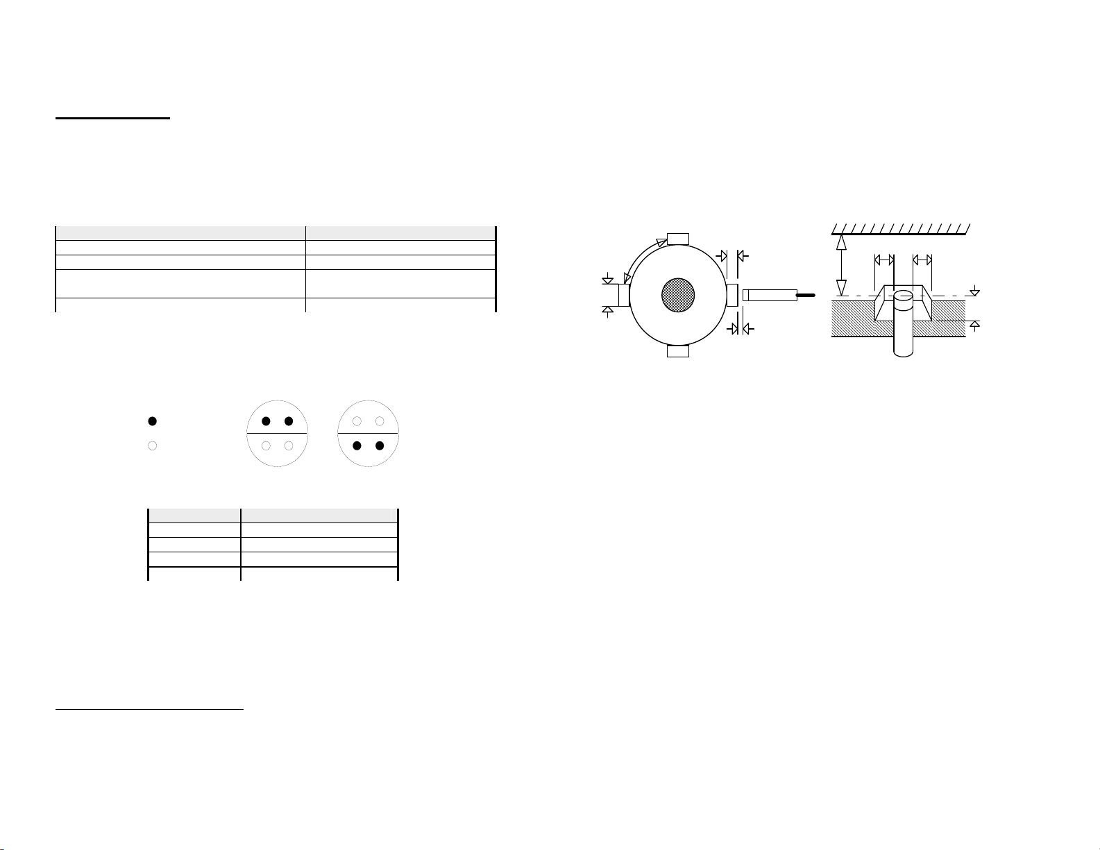
It is IMPORTANT that the sensor and targets should be rigidly mounted so they do
not move with vibration. Targets should be at least 10mm (5/8”) diameter and stand
4mm (5/32”) proud (Fig.1). Smaller targets can be used but this will reduce the range.
Small aluminium, brass or copper targets will generally NOT work.
Nothing other than the targets should come within 6mm (1/4”) of the end of the
sensor. If the sensor mounting position is to be recessed, then a hollow of 24mm
(15/16”) diameter and at least 4mm (5/32”) deep should be allowed around the sensor
(Fig 2).
4 (5/32) min
1.5 (60thou)
10 min
(3/8)
(15/16)
24 min
688
Dimensions in mm (in)
4
(1/4) (5/16) (5/16)
(5/32)
Fig. 1 Fig. 2
Sensor Adjustment.
1. Connect the sensor to the system and turn on the power.
2. Assemble the first (rear) nut onto the sensor.
3. Insert the sensor into the mounting bracket hole and fit the front nut.
4. Rotate the wheel and move the sensor slowly forward by undoing the rear nut
counter-clockwise until the light comes on for every target.
5. Undo the rear nut half a turn more.
6. Without rotating the sensor or rear nut, finger-tighten the front nut.
7. Tighten the rear nut with a 13mm AF spanner. Do NOT let the sensor rotate.
Do not over-tighten – half a flat of the nut should be sufficient.
The sensor has an in-built light (LED) which can be used to check that both the
mechanical and electrical installations have been performed correctly. This light
should be ON when a target is in front of the sensor.
Checks for correct installation and adjustment
1. Rotate the wheel and check that the light comes on for each target and goes off
between each target.
2. Check that both the sensor and targets are rigidly mounted.
3. Check that the front nut does not cover any part of the sensing end.
4. IMPORTANT Check the gap between sensor and any of the targets is NOT less
than 0.5mm (20thou). so there is no risk of the sensor touching targets in
operation.
Please see the user manual of your system for setting the wheel circumference
and pulses per revolution.
Other Stack Accessories manuals


