Stack ST994 User manual
INSTALLATION INSTRUCTIONS
Wide-Band Exhaust Gas Oxygen
Sensor Interface
ST994 / ST996
CAUTION: CAREFULLY READ INSTRUCTIONS BEFORE PROCEEDING
OVERVIEW
The Control Unit is a dual channel air/fuel ratio
(AFR) metering system designed to be used with an exist-
ing data acquisition system. The system has two 0-5 volt
analog AFR outputs. The compact size and wide supply
voltage range also allow operation from small rechargeable
batteries in a broad range of applications.
By utilizing miniature surface mount electronics
technology, digital signal processing techniques, and a
switching power supply for the sensor heater, the Control
Unit provides the same level of accuracy as lab systems
costing much more.
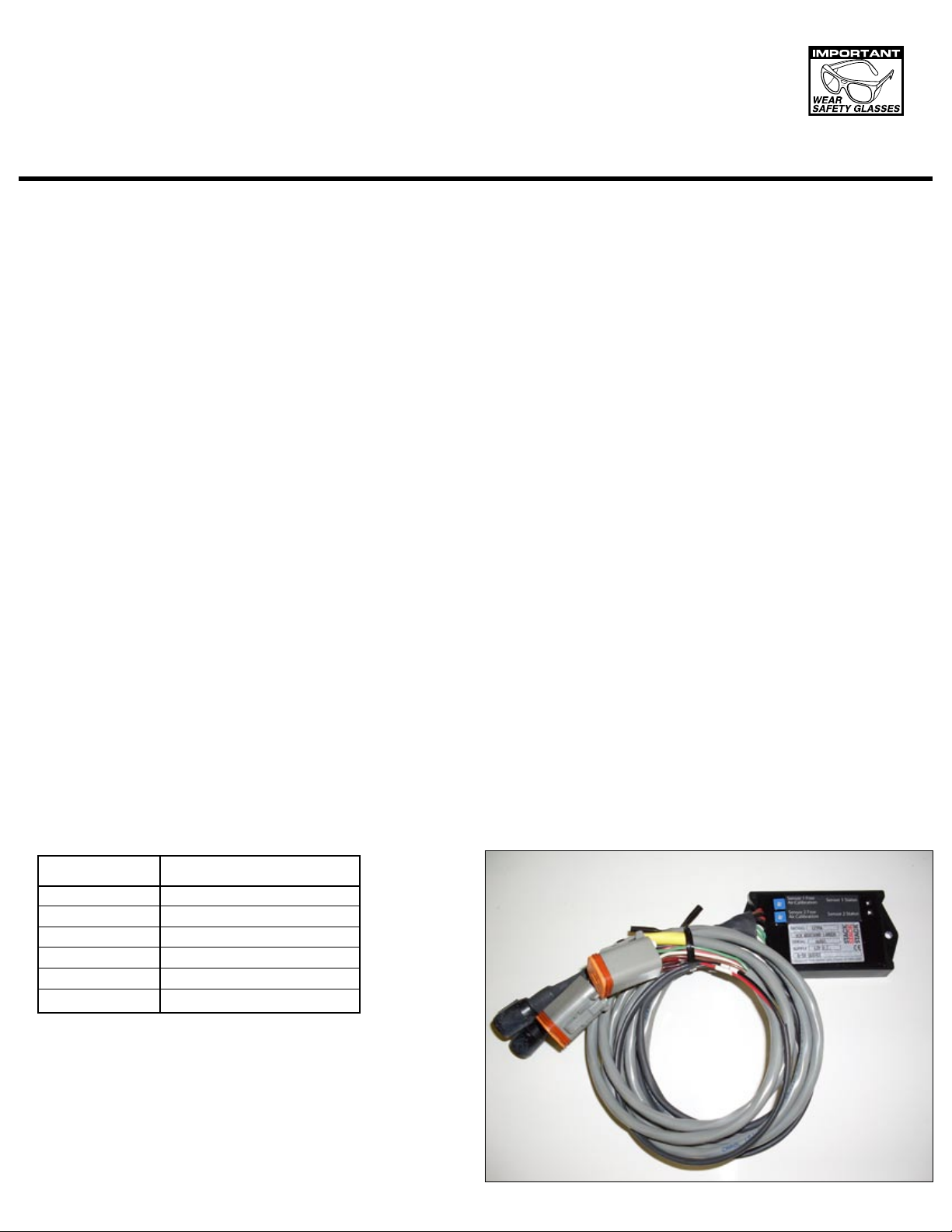
REPLACEMENT SENSORS AND
ACCESSORIES
We offer replacement sensors with Deutsch
connector installed: ST269552.
If you plan to terminate your own sensors, use the
following color chart:
Terminal Wire Color
1 Red
2 Black
3 Yellow
4 White
5 Gray
6 Seal
Figure 1 – Control Unit
INSTALLATION
1. Turn off the ignition switch and disconnect the battery
ground cable before proceeding.
2. The Bosch LSU 4.2 sensors should be located on the
header pipe about 6-8 inches from the head ange.
Ideally the sensor tip should face down to avoid accu-
mulation of condensation. When choosing a mounting
location, allow several inches clearance for the sensor
wire harness. The wire harness must exit straight out
from the sensor. Do not loop the harness back onto the
sensor body.
3. 18 x 1.5 mm weld nuts must be welded onto the ex-
haust pipe. After welding, run an 18 x 1.5 mm tap
through the threads. Failure to clean the threads may
result in sensor damage. Note that most automotive
mufer shops are familiar with oxygen sensor weld nut
installation on custom pipes. Do not install the sensors
until after the free air calibration procedure described in
STACK
STACK
STACK
®

5. Connect the Bosch sensors to the 6 pin mating connec-
tors on the Control Unit wire harness. Extension cables
are available. The cable for sensor 1 exits at the top of
the Control Unit and is identied with a yellow band.
6. Refer to Figure 2. Connect the heavy black wire to a
good chassis ground location. Keep the ground
connection as short as possible.
7. If your race vehicle uses any type of CD (capacitive
discharge) ignition such as the MSD 6, 7, or 8 series,
you must properly ground and lter the ignition unit. Un-
less your ignition unit is directly connected to the battery
terminals, you must install a lter capacitor such as MSD
P/N 8830.
8. Connect the red wire to switched +12 volt power.
9. Reconnect the battery ground cable.
SENSOR 1 CABLE
IDENTIFIED BY
YELLOW BAND
TO SWITCHED
+12V POWER
0-5V OUTPUT SCALED
AFR = 10 + (2 x VOLT)
RED
S1
S2
HEAVY BLACK
SENSOR 1
INPUT
SENSOR 2
INPUT
SENSOR 1 AFR
OUTPUT
SENSOR 2 AFR
OUTPUT
INPUT
INPUT
POWER
GROUND
SENSOR
Figure 2 - Controller Hookup
DATA ACQUISITION
SYSTEM
SENSOR

SENSOR LIFE AND CALIBRATION
When used in a racing application with leaded
petrol, sensor life will probably be less than 10 hours.
Free air calibration should be performed on a regular
basis, such as before the start of every test session or
race event. If free air calibration fails, the sensor should
be replaced. Free air calibration must be performed in
an environment free of hydrocarbon vapors. Typical race
shop environments may prove to be too contaminated.
Even outdoors, free air calibration can fail if a carburetor
bowl has recently been removed or another vehicle is
running nearby. In general, sensors that are at the end of
their useful life will fail free air calibration.
OPERATION
The Control Unit has red status LEDs for each
channel. When power is turned on, the LEDs blink at a
slow rate until the corresponding sensor has reached
normal operating temperature.
After installation, the Control Unit requires free air
calibration. This should be done with the sensors dangling
in free air. The environment must be free of hydrocarbon
vapors. We suggest that you perform the free air
calibration outdoors. Turn the free air calibration trimpots
on the Control Unit full counterclockwise. Turn on power
and wait for 60 seconds so the system can fully stabilize.
Then slowly turn each free air calibration trimpot clockwise
until the corresponding LED starts ashing at a rapid rate.
Try to set each trimpot at the point where its LED just
starts to ash.
The free air calibration procedure should be
performed at reasonable intervals (every 250-500 hours if
using unleaded petrol or every 2-5 hours if using leaded
racing petrol) or whenever a sensor is replaced. If you
cannot get an LED to ash when its trimpot is turned full
clockwise, you either have a damaged sensor or very high
hydrocarbon levels in your environment.
The Control Unit includes internal diagnostics for
abnormal battery voltage (less than 11 volts or greater
than 16.5 volts), sensor open circuit, and sensor short
circuit conditions. A fault condition causes the status LEDs
to blink at the slow rate.
EXHAUST CONSIDERATIONS
The Control Unit system may give inaccurate
results in certain situations:
Excessive exhaust back pressure. Wide-band
sensors are affected by back pressure. Excessive back
CAUTION: Racing petrol containing lead
will quickly degrade the sensors. Under
these conditions, expected sensor life is
less than 10 hours. There is no warranty
on sensors.
pressure causes exaggerated AFR indications under
rich and lean conditions, but has little effect at 14.7 AFR
(stoichiometric). Race vehicle exhaust systems are free
owing and problems with exhaust back pressure are not
likely.
Exhaust reversion. Reversion is the term for a
negative pressure wave that can suck ambient air back into
the exhaust and cause an erroneous lean AFR indication.
Open “drag pipes” usually suffer from reversion effects and
may not be suitable for use with the this system except at
or near wide open throttle. Reversion effects will be most
noticeable at idle, part throttle low RPM, and deceleration.
Excessive scavenging. Tuned exhausts in
combination with a high overlap camshaft prole can pull
unburned air and fuel mixture through the cylinder into the
exhaust and cause an erroneous rich AFR indication. The
same effect can occur with high boost turbo/supercharger
applications.
Misring. If the AFR is so rich that the engine
misres, high levels of oxygen will remain in the exhaust
gas and result in an erroneous lean indication.
ENGINE TUNING GUIDELINES
Higher AFR values correspond to a leaner (less fuel)
condition. The practical operating range for most engines
using gasoline fuel is from approximately 11.5 to 14.7 AFR.
Combustion of a stoichiometric mixture (exactly enough
air to burn all the fuel) results in 14.7 AFR indication.
Automotive engines with catalytic converters operate near
14.7 AFR during cruise and idle. Race engines usually
require a richer mixture to limit cylinder head temperature
and prevent detonation. The table below lists reasonable
AFR values for race engines without emission controls.
Operating Mode Recommended AFR
Cold Start (rst 30 sec) 11.5-12.5
Idle 12.8-13.5
Part Throttle Cruise 13.0-14.0
Wide Open Throttle 12.5-12.8 (values down to
11.5 may be used to
reduce detonation)
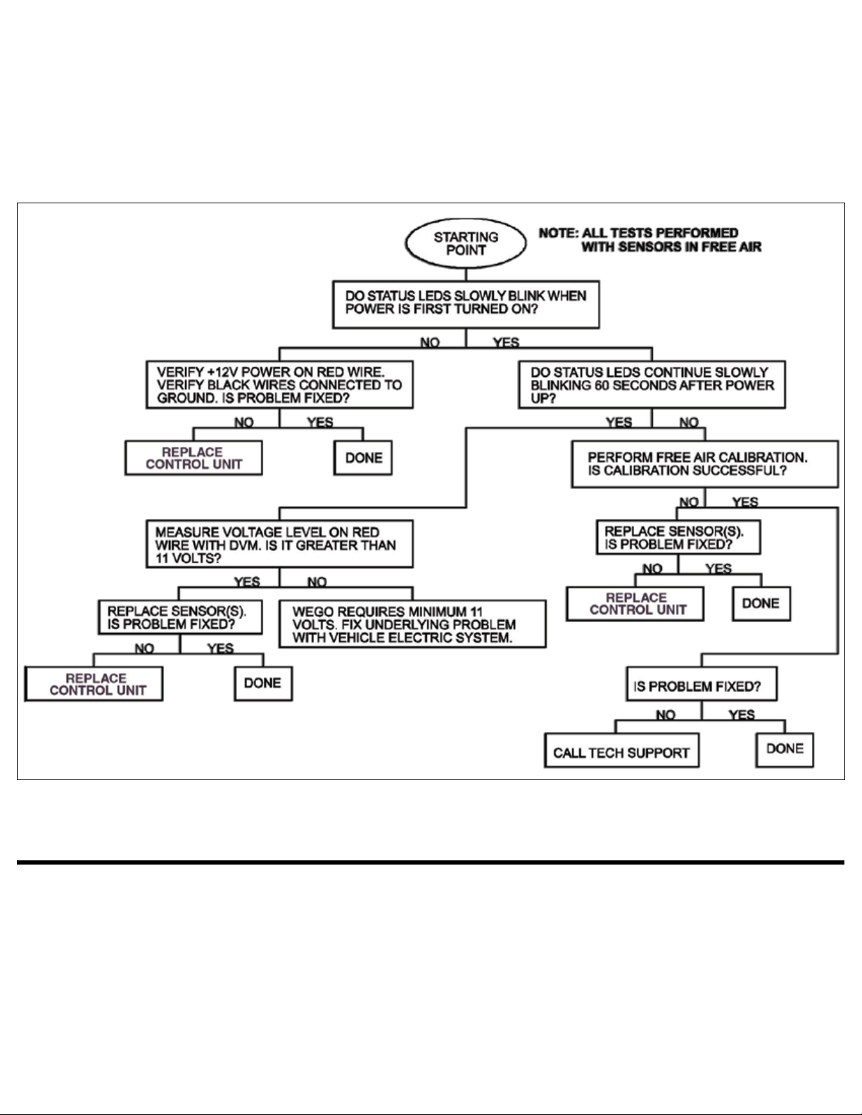
TROUBLESHOOTING FLOWCHART
Follow the troubleshooting owchart shown on the next page. Experience has shown that most units returned for war-
ranty are OK and another problem, such as user error, degraded sensors, or bad power connections is later identied.
WARRANTY
Stack Limited warrants this product (excepting associated sensors which are consumable items - there is no warranty on sensors.) to be free from defects caused
by faulty materials or poor workmanship for 1 year from the date of consumer purchase. This warranty applies only to the original purchaser of product and is
non-transferable. All implied warranties shall be limited in duration to the said warranty periods above. Breaking the instrument seal, improper use or installation,
accident, water damage, abuse, unauthorized repairs or alterations voids this warranty. Stack Limited disclaims any liability for consequential damages due to
breach of any written or implied warranty on all products manufactured by Stack Limited.
www.stackltd.com
Stack Ltd. Wedgwood Road, Bicester OX26 4UL UK
© 2010 STACK, Ltd. ST54115-001 03/03/10
This manual suits for next models
1
Other Stack Accessories manuals


Popular Accessories manuals by other brands


Multibrackets
Multibrackets M Wall installation manual

Popp
Popp Ei600ZW quick start

Thule
Thule Omnistor 9200 3026 Series instructions

Progress
Progress Replacement Motion Sensor P6036 owner's manual

Porter
Porter 1235 Installation, operation & maintenance manual

KMC Controls
KMC Controls STE-8001 installation guide