Gira 5201 00 User manual

KNX
Product documentation
Last edited:
25/03/2019
Alarm control unit Connect
Order No. 5201 00

KNX
Product documentation
Order No. 5201 00 Page 2
1. About the product ............................................................................................... 3
1.1. Product catalogue ....................................................................................................................... 3
1.2. Intended use................................................................................................................................ 3
1.3. Device components..................................................................................................................... 3
1.4. State of delivery........................................................................................................................... 3
1.5. Technical data ............................................................................................................................. 4
2. Safety notes......................................................................................................... 5
3. Installation and electrical connection.................................................................. 6
3.1. Housing cover.............................................................................................................................. 6
3.2. Installation ................................................................................................................................... 7
4. Configuring KNX functions.................................................................................. 9
4.1. Configuring KNX devices............................................................................................................. 9
4.2. Example of use .......................................................................................................................... 10
4.2.1.KNX connection .................................................................................................................. 10
4.2.2.Secure remote access with Gira S1 .................................................................................... 11
4.3. KNX functions............................................................................................................................ 11
4.4. Topology.................................................................................................................................... 12
4.4.1.Alarm control unit Connect in main line ............................................................................. 12
4.4.2.Alarm control unit Connect in area line .............................................................................. 14
5. Starting up......................................................................................................... 16
5.1. ETS configuration and start-up.................................................................................................. 16
5.2. GPA configuration type ............................................................................................................. 16
5.2.1.External detectors ............................................................................................................... 17
5.3. Programming physical address and application software ........................................................ 19
6. Software............................................................................................................ 21
6.1. IP address configuration............................................................................................................ 21
6.2. Object table ............................................................................................................................... 22
7. Parameters ........................................................................................................ 28
7.1. General information................................................................................................................... 28
7.2. Main security area, security area 2, security area 3, security area 4 ........................................ 28

About the product
Order No. 5201 00 Page 3
1. About the product
1.1. Product catalogue
Product name: Alarm control unit Connect
Order No.: 5201 00
Application: Alarm control unit
Design: Surface-mounted
1.2. Application
The alarm control unit Connect is a wireless alarm system and the core unit of the Gira Alarm Connect
security system. The alarm control unit Connect is designed for indoor use to protect apartments, pri-
vate homes and small or medium commercial properties.
Using a KNX IP router, the alarm control unit Connect can be integrated into a KNX installation. A KNX
installation allows use of existing KNX sensors.
• Connects up to 64 wireless components including wireless operating unit, alarm signal units (wire-
less indoor siren, wireless outdoor siren) or wireless I/O module
• 4 security areas
• Encrypted-data access for setting up via Internet and Gira S1/Gira smart home app
• Gira G1 as client for Alarm Connect security system to act as additional operating and display unit
• Connects landline phone for remote alarming (optional: GSM module)
• In the event of mains failure, internal rechargeable battery pack takes over power supply for at least
12 hours
1.3. Device components
1 Connection: telephone
2 Connection: LAN (RJ45)
3 Slot: GSM module
4 Connection: Rechargeable battery pack
5 Connection: AC 230 V
6 Housing cover (open)
7 Plug terminals: Output
8 Plug terminals: Input
9 Rechargeable battery pack
10 Terminal plugs: reserved for future applications
11 Pairing button and status LED
1.4. State of delivery
When delivered, the device is in passive mode, i.e. it does not send telegrams through the bus. You
can use ETS, version 5 or higher, and the Gira Project Assistant (GPA), version 4 or higher, to program
and start up the alarm control unit.
IP address is assigned via DHCP. Should the alarm control unit not receive an address using this
method, an auto IP (address range from 169.254.1.0 to 169.254.254.255) is issued after a certain
waiting time.
You can also issue a static IP address via the ETS or the Gira Project Assistant. You can set IP address,
IP subnet mask and IP standard gateway here.
LN
911 6
75
21 34
LN
LAN
10
AMT TEL
A2B2
BA
8

About the product
Order No. 5201 00 Page 4
1.5. Technical data
Power supply
External: AC 230 V, 0.9 A, 50/60 Hz
Internal Battery pack, rechargeable
Nominal power: max. 30 W
Rechargeable battery pack
Type: Lithium, rechargeable
Capacity: 5.8 Ah
Voltage: 7.2 V
Service life: approx. 5 years
Battery pack charging time: 80% in 12 hours
Backup battery
Type: CR1225
Service life: approx. 5 years
Characteristics of electrical outputs
Per output: max. 200 mA
Total outputs: 1 A
Wireless
Frequency band: 868.0 - 868.6 MHz
868.7 - 869.2 MHz
Range: 100 m (free field)
Device – general
Connections:
LAN: RJ45
Phone: Analog via terminal
Plug terminals: 2x input, 2x output
GSM module: 1 slot
Optical display: Status LED (red/green)
Mounting height (recommended): at least 1.5 m
Ambient temperature: -10 °C to +55°C
Storage temperature: -25 °C to +60 °C
Humidity: 93 %
Security class: 2
Environmental class: II
Dimensions of housing (H x W x D): 285 x 170 x 30 mm (without adapter frame)
Dimensions of housing (H x W x D): 285 x 170 x 46 mm (with adapter frame)

Safety notes
Order No. 5201 00 Page 5
2. Safety notes
Safety notes
Electrical devices may only be installed and connected by a qualified electrician.
Improper installation may result in serious injury, e.g. from electrical shock or fire, as well as
equipment damage.
Do not open the device housing. Always observe the device’s technical specifications.
This product contains a rechargeable battery. Keep new and used batteries away from children.
These instructions are part of the product and must remain with the end customer.

Installation and electrical connection
Order No. 5201 00 Page 6
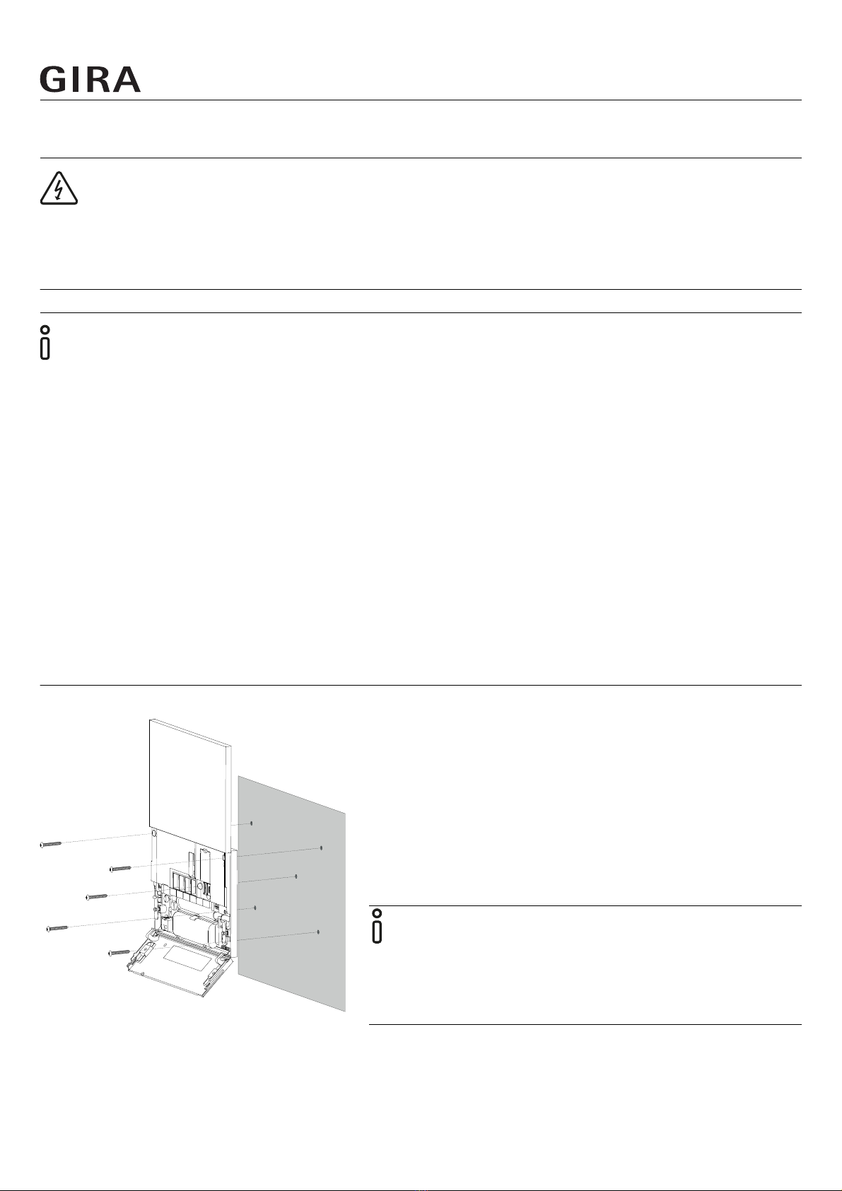
3. Installation and electrical connection
3.1. Housing cover
1 Housing cover (closed = position 0)
2 Status LED (under housing cover)
The alarm control unit only operates with the housing
cover closed.
1 Mounting holes
2 Opening for mains power cable
3 Opening for Ethernet cable
4 Disconnecting surface for tamper contact
Position 0
Housing cover closed (factory settings). After connection
to the battery pack and 230 V as well as project commis-
sioning:
Housing cover closed = operating mode.
Position 1
Push the housing cover up until the screws of the hinged
cover are exposed and the housing cover is noticeably
blocked. Loosen the two screws in the hinged cover and
push the housing cover further up (this position can only
be achieved with the screws are loosened!). The housing
cover can be removed.
Position 2
Housing cover removed = configuration mode.
Only the upper mounting holes and the slot of the GSM
module are accessible when the hinged cover is closed.
When the hinged cover is open, all connections (battery
pack, LAN, telephone, etc.) and the mounting holes are
accessible.
2 1
2 1
43
1
1
1
LN
LN
LAN
LN
LN
LAN
Position 1
Position 2
Position 0
Position 0
Position 1
1.
3.
2.
Installation and electrical connection
Order No. 5201 00 Page 7
3.2. Installation
DANGER!
Lethal danger from electric shock.
De-energise the device. Cover live parts.
Installation notes
• Always mount in the main security area.
• Do not mount on external walls as these can be tampered with, e.g. opened up by drilling.
• Only mount in locations in which the temperature is constant (e.g. no direct sunlight).
• Choose the installation location so that it is within the detection range of a motion detector, or can-
not be reached without triggering an alarm.
• Mount horizontally (the housing cover can only be opened upwards).
• Recommended mounting height: at least 1.50 m above the floor.
• Keep the alarm control unit at least 50 cm clear of ceilings, metal objects and other devices (unsuit-
able: metal doors or cabinets or direct vicinity of fuse boxes and electricity meters).
• Mounting methods other than wall mounting are not allowed.
• Select the installation location so that the wireless signals between the alarm centre and the wire-
less operating unit can be easily sent or received during test operation.
1. Unpack the alarm control unit.
2. Remove the housing cover.
3. Align the alarm control unit, mark the drilling holes,
drill and insert the wall plugs.
4. Mount the alarm control unit. The disconnecting sur-
face of the tamper contact (see "Rear Side - Device
Description") must be secured with a screw.
5. Disconnect the mains voltage and wire the alarm cen-
tre accordingly to the application.
Wall mounting
Make sure the wall surface is level. In the case of an
uneven wall surface, there is the possibility that the
housing will move during installation. This can cause
the housing cover to be improperly inserted and
closed.
Installation and electrical connection
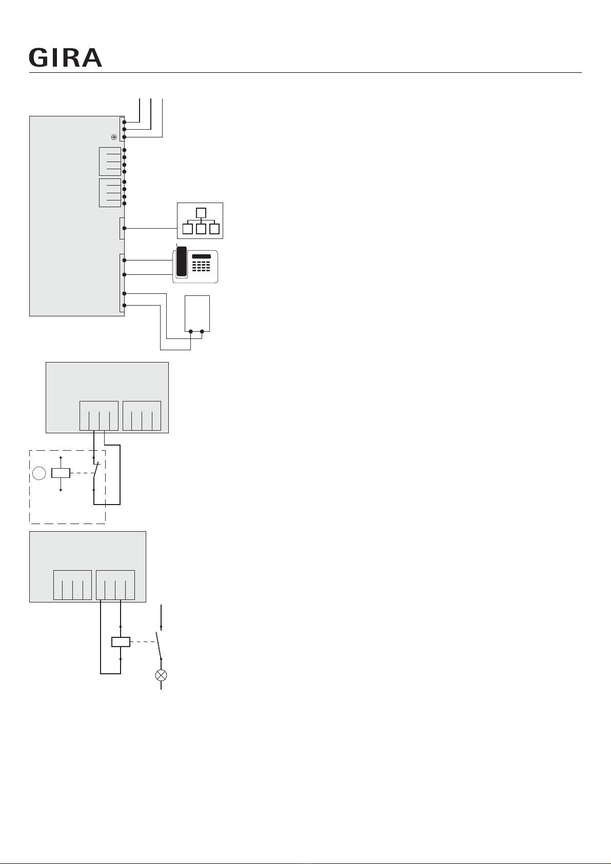
Order No. 5201 00 Page 8
Use power lines with a cable cross-section of 1.5 to 2.5
mm².
AMT Connection: TAE box
TEL Connection: telephone
LAN Connection: Ethernet cable
Connection example for inputs
The following cable type can be connected to the inputs:
IY(ST)Y with Ø 0.6 to 0.8 mm, max. length 100 m.
INPUTS Input plug terminals
12V DC 12 V, max. 1 A
GND Ground is wired as a signal
IN1, IN2 Contact (NC/NO)
A Example: Fault relay heating system
Connection example for outputs
OUTPUTS Output plug terminals
12V DC 12 V, max. 200 mA
GND Ground
OUT1, OUT2 Open-Drain
Max. switching current: DC 12 V/200 mA
1. Connect the Ethernet cable to the LAN port.
2. Connect the battery pack and switch on the mains voltage. Wait for the initialisation phase.
3. Configure the project in the GPA and transfer it to the alarm centre memory (also see the enclosed
Quick Start Guide).
4. Close the hinged cover on the battery compartment and tighten the two screws.
Leave the housing cover off and stay in configuration mode.
LN
NLPE
12V
GND
IN 1
IN 2
12V
GND
OUT1
OUT2
INPUTS OUTPUTS
AMT TEL
A B B2 A2 LAN
TAE
ab
12V
GND
IN 1
IN 2
12V
GND
OUT1
OUT2
INPUTS OUTPUTS
A
12V
GND
IN 1
IN 2
12V
GND
OUT1
OUT2
INPUTS OUTPUTS
L1
N
A1
A2

Configuring KNX functions
Order No. 5201 00 Page 9
4. Configuring KNX functions
4.1. Configuring KNX devices
The alarm control unit Connect is a product of the KNX system and complies with the KNX guidelines.
Detailed specialist knowledge is required. The alarm control unit Connect is a security system for an
existing or newly installed KNX system.
Initial start-up is performed via ETS 5 or higher.
Notes
• You can find the KNX product database and the technical documentation on the internet at
www.download.gira.de.
KNX/IP uses Multicast to mirror KNX bus group communication on IP. To couple the alarm control unit
Connect with a twisted pair bus (TP bus), always use a KNX IP router.
Tip
Faster configuration via direct IP connection
• In ETS 5, select Options under the Bus tile and check whether Use direct IP connection if available
is activated. This will make transmission of the KNX configuration from the ETS to the alarm control
unit Connect faster.
Configuring KNX functions
Order No. 5201 00 Page 10
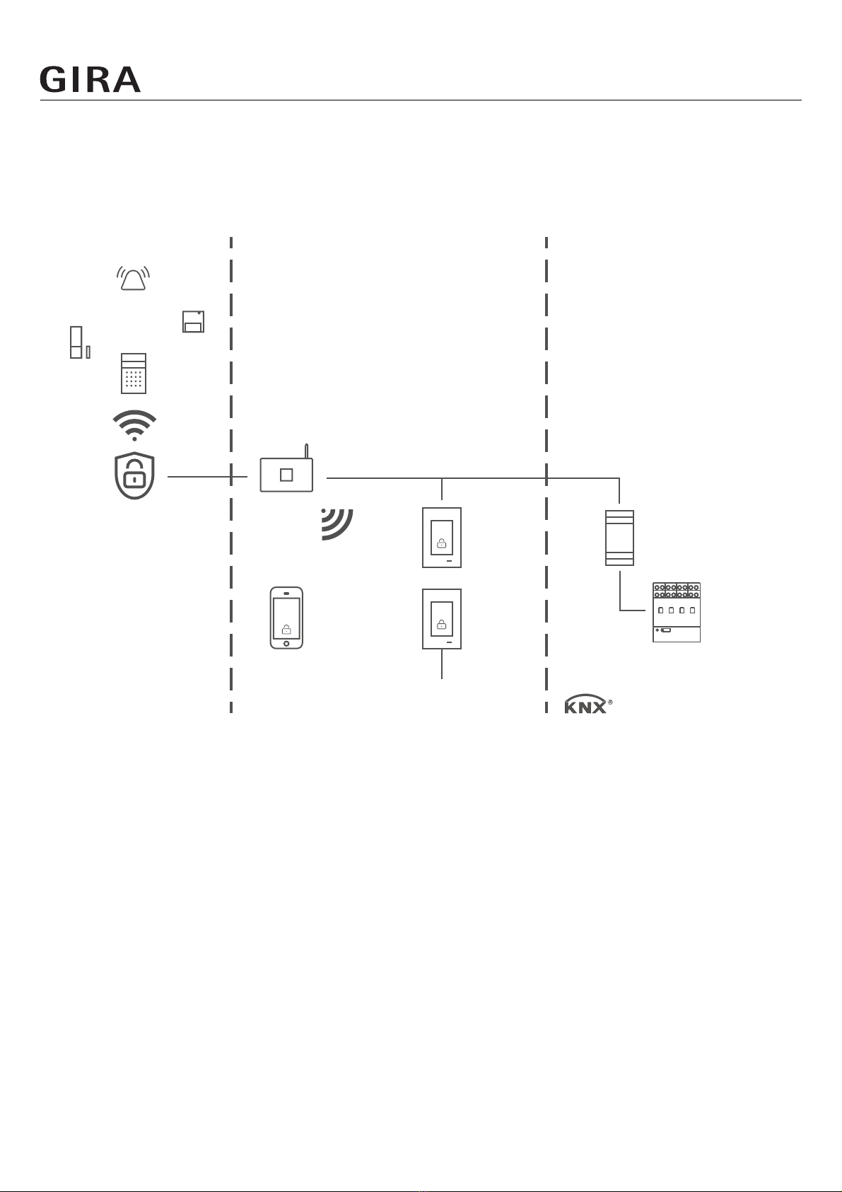
4.2. Application example
4.2.1. KNX connection
The Gira Alarm Connect security system with Gira G1 alarm client and smartphone app to act as addi-
tional operating and display devices. Connected to KNX via KNX IP router.
868 MHz LAN / WLAN
AC 230 V
KNX IP-Router
TP
Gira Alarm Connect
security system
Router
Access via
Gira App
Gira G1
Gira G1

Configuring KNX functions
Order No. 5201 00 Page 11
4.2.2. Secure remote access with the Gira S1
The Gira S1 is installed in the customer's home network and prepares the home network for secure
access via the Internet. It connects to the Gira device portal automatically using the existing Internet
access. Communication between the Gira S1 and the Gira device portal is encrypted using AES and
secured with digital certificates (for details, see Gira S1 operating instructions).
Smartphone and app then use encrypted, direct access to the alarm control unit Connect through the
Gira device portal.
4.3. KNX functions
Depending on the installation, the following KNX functions can be performed using the alarm control
unit Connect:
• Query alarm control unit status
• Burglar alarm, panic alarm, fire alarm, tamper alarm, device monitor, technical alarm
• Query arming status
• Door chime
At home Internet On the way
Gira Alarm Connect
security system
Gira device portal Secure remote
access via Gira App
Router Gira S1
Access via Gira App
Configuring KNX functions
Order No. 5201 00 Page 12
4.4. Topology
The alarm control unit Connect is integrated into either the main line or area line of the KNX system
via a KNX IP router. For this, the alarm control unit Connect can either be integrated into the main line
or area line.
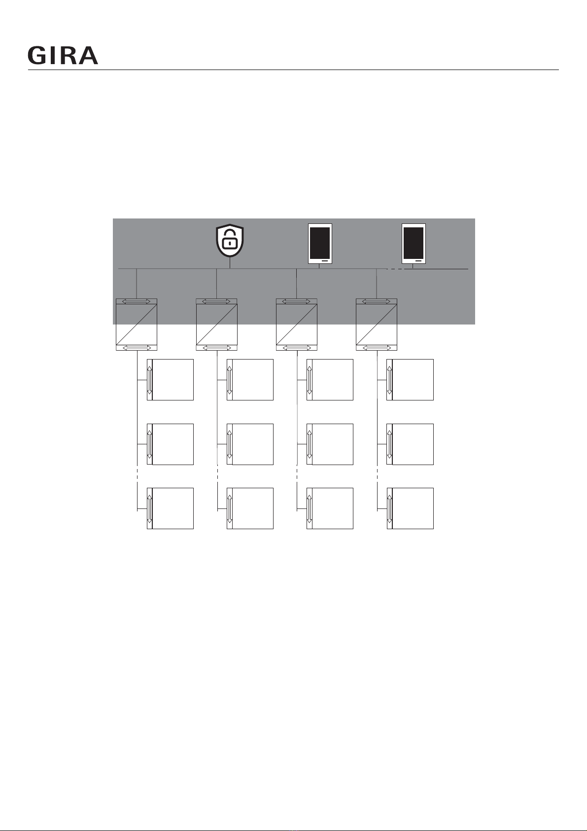
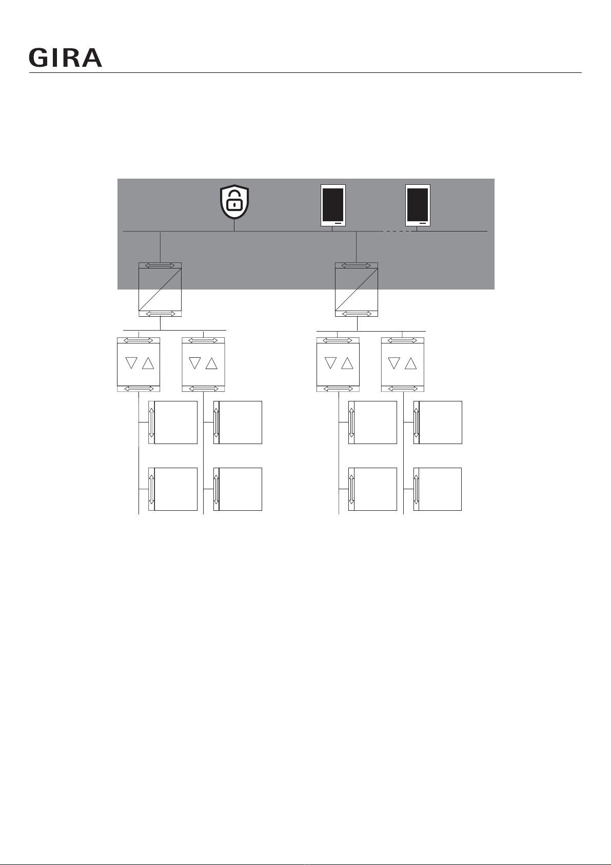
4.4.1. Alarm control unit Connect in main line
The following topology illustrates how the alarm control unit Connect is operated in the main line
together with the Gira G1. in this case the KNX IP router is used as a line coupler.
Topology example: Alarm control unit Connect in main line
IP-Network
Alarm control
unit Connect
GIRA
Gira G1
GIRA
Gira G1
IP
KNX
1.0.1 1.0.2 1.0.n
Bus device
1.1.1
Bus device
1.1.2
Bus device
1.1.n
KNX IP-
Router
1.1.0
KNX
IP
Bus device
1.2.1
Bus device
1.2.2
KNX IP-
Router
1.2.0
KNX
IP
Bus device
1.3.1
Bus device
1.3.2
KNX IP-
Router
1.3.0
KNX
IP
Bus device
1.4.1
Bus device
1.4.2
KNX IP-
Router
1.4.0
KNX
IP
Bus device
1.2.n
Bus device
1.3.n
Bus device
1.4.n
n = 3 - 254

Configuring KNX functions
Order No. 5201 00 Page 13
When installing the alarm control unit Connect in the main line, the configuration in ETS 5 would be
as follows:
ETS 5 screenshot: Alarm control unit Connect in main line
Configuring KNX functions
Order No. 5201 00 Page 14
4.4.2. Alarm control unit Connect in area line
The following topology illustrates how the alarm control unit Connect is operated in the area line
together with the Gira G1. In this case the KNX IP router is used as an area coupler and the area/line
coupler is used as a line coupler.
Topology example: Alarm control unit Connect in area line
IP-Network
Bus device
1.1.1
Bus device
1.1.2
Alarm control
unit Connect
GIRA
Gira G1
GIRA
Gira G1
IP
KNX
Bus device
1.2.2
Bus device
1.2.1
LC
1.1.0
Main line 1
LC
1.2.0
KNX IP-Router
1.0.0
0.0.1 0.0.2 0.0.(3 - 254)
KNX
IP
Bus device
2.1.1
Bus device
2.1.2
Bus device
2.2.1
LC
2.1.0
Main line 2
LC
2.2.0
KNX IP-Router
2.0.0
KNX
IP
Bus device
2.2.2

Configuring KNX functions
Order No. 5201 00 Page 15
When installing the alarm control unit Connect in the area line, the configuration in ETS 5 would be
as follows:
Topology example: Alarm control unit Connect in area line

Start-up
Order No. 5201 00 Page 16
5. Start-up
ETS search paths: Security/alarm control unit/alarm control unit Connect
Configuration: S-mode standard
Available application program
Name: Alarmzentrale Connect F03010
Version: ETS 5 or higher
From mask version: 57b0
5.1. ETS configuration and start-up
Configuring and starting up the alarm control unit Connect requires ETS 5 or higher and the Gira Pro-
ject Assistant (version 4 or higher). The required product database is available in *.knxprod format.
The corresponding application program has version number 1.0.
5.2. GPA configuration type
In the GPA project configuration, select security system for the Gira Alarm Connect security system
and
Use KNX communication objects if you wish to use the alarm control unit Connect’s KNX communi-
cation objects in the ETS.

Start-up
Order No. 5201 00 Page 17
5.2.1. External detectors
External detectors are detectors that trigger an alarm via, for example, a KNX communication object
or a data point.
If you activate this option, you will also need to activate the alarms that you want the external detec-
tors in this security area to trigger. The KNX communication objects can only trigger an event in the
ETS application if the corresponding alarms have been activated in the GPA.

Start-up
Order No. 5201 00 Page 18
If you wish to use this function in the KNX system, you also need to activate Use KNX communication
objects in the project configuration.
If you wish to trigger an alarm via, the GPA data points, select the desired alarms here.
Notes
• ETS always shows the alarm control unit’s communication objects. However, they can (for security
reasons) only be used if the Use KNX communication objects option has been deliberately activated
in the project configuration.
• The alarms’ data points are always shown in the data point view but only perform a function if the
corresponding alarm has been set here, too.

Start-up
Order No. 5201 00 Page 19
5.3. Programming the physical address and application software
The alarm control unit Connect has been connected and is ready for operation. The bus is powered.
Programming is done in the programming environment of the ETS 5. Connection to the device will be
through IP.
Notes
• You can only program the physical address and application software when the housing cover is
open.
Important: When you open the housing cover, a tamper alarm triggers.
• Use the Gira Project Assistant (version 4 or higher) to start programming mode. The alarm control
unit Connect does not have a programming button or programming LED.
1. Start the GPA and select the project.
2. Double-click the data points tile.
The data points view opens.

Start-up
Order No. 5201 00 Page 20
3. Start monitoring.
4. Select the GIALRMKXIP device data point.
5. Open KNX programming mode.
6. Enter value 1 and hit enter to confirm.
Programming mode activates.
7. Program the physical address using the ETS.
8. Note the physical address on the alarm control unit Connect’s hinged cover.
Table of contents
Other Gira Control Unit manuals


