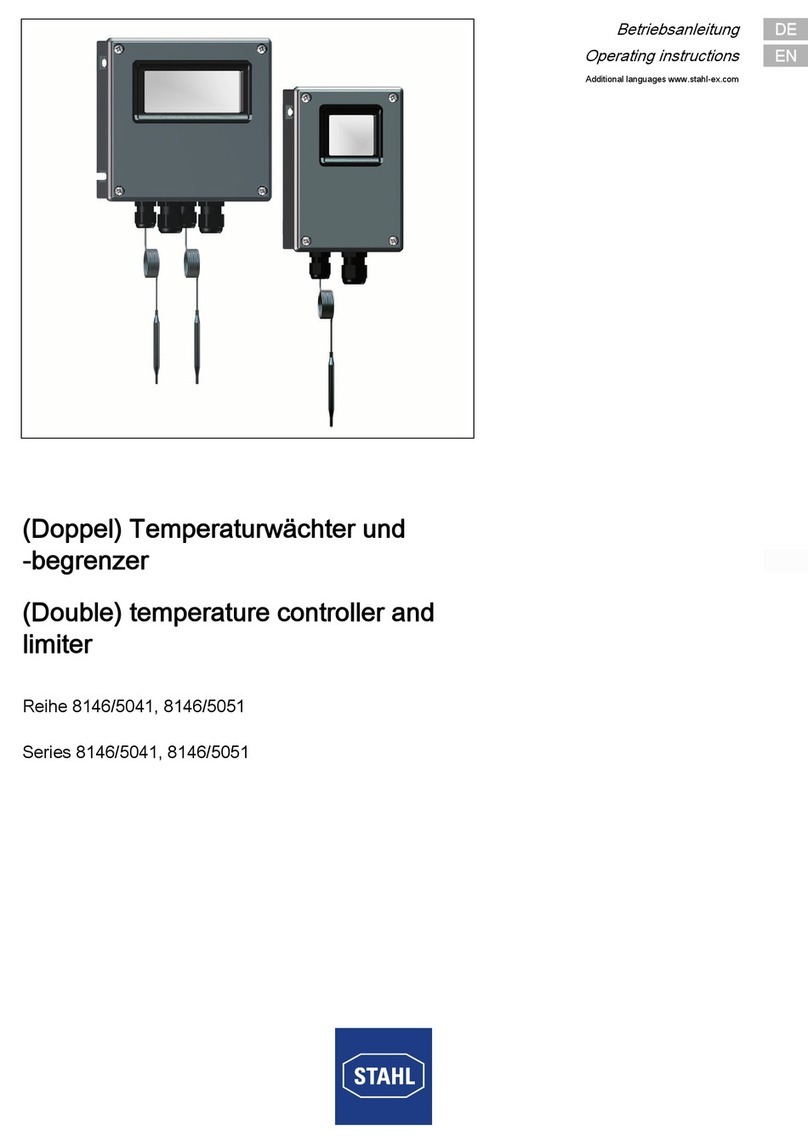
Stahl 8146/5041 Series User manual

EN
EN
EN
EN
EN
EN
EN
EN
EN
EN
EN
EN
EN
EN
EN
EN
EN
EN
EN
EN
EN
EN
EN
EN
EN
Operating instructions
Additional languages www.stahl-ex.com
EN
(Double) temperature controller and
limiter
Series 8146/5041, 8146/5051

2(Double) temperature controller and
limiter
Series 8146/5041, 8146/5051
EN
EN
EN
EN
EN
EN
EN
EN
EN
EN
EN
EN
EN
EN
EN
EN
EN
EN
EN
EN
EN
EN
EN
EN
EN
Contents
1 General Information ............................................................................................3
1.1 Manufacturer .......................................................................................................3
1.2 Information regarding the operating instructions .................................................3
1.3 Further documents ..............................................................................................3
1.4 Conformity with standards and regulations .........................................................3
2 Explanation of the symbols .................................................................................4
2.1 Symbols in these operating instructions .............................................................4
2.2 Warning notes .....................................................................................................4
2.3 Symbols on the device ........................................................................................5
3 Safety notes ........................................................................................................5
3.1 Operating instructions storage ............................................................................5
3.2 Safe use ..............................................................................................................5
3.3 Modifications and alterations ..............................................................................5
4 Function and device design ................................................................................5
4.1 Function ..............................................................................................................6
5 Technical data .....................................................................................................6
6 Transport and storage .......................................................................................11
7 Mounting and installation ..................................................................................11
7.1 Dimensions / fastening dimensions ..................................................................11
7.2 Mounting / dismounting, operating position ......................................................11
7.3 Installation .........................................................................................................13
8 Commissioning .................................................................................................16
8.1 Adjustment of temperature controller ................................................................17
9 Operation ..........................................................................................................17
10 Maintenance and repair ....................................................................................18
10.1 Maintenance .....................................................................................................18
10.2 Maintenance .....................................................................................................19
10.3 Repair ...............................................................................................................19
10.4 Returning the device .........................................................................................19
11 Cleaning ............................................................................................................19
12 Disposal ............................................................................................................20
13 Accessories and Spare parts ...........................................................................20

240634 / 8146662300
2016-07-11·BA00·III·en·02
General Information
3
(Double) temperature controller and
limiter
Series 8146/5041, 8146/5051
EN
EN
EN
EN
EN
EN
EN
EN
EN
EN
EN
EN
EN
EN
EN
EN
EN
EN
EN
EN
EN
EN
EN
EN
EN
1 General Information
1.1 Manufacturer
R. STAHL Schaltgeräte GmbH
Am Bahnhof 30
74638 Waldenburg
Germany
Phone: +49 7942 943-0
Fax: +49 7942 943-4333
Internet: www.stahl-ex.com
E-Mail:[email protected]
1.2 Information regarding the operating instructions
ID-No.: 240634 / 8146662300
Publication Code: 2016-07-11·BA00·III·en·02
Hardware version: n/a
Software version: n/a
The original instructions are the English edition.
They are legally binding in all legal affairs.
1.3 Further documents
• Data sheet
For further languages, see www.stahl-ex.com.
1.4 Conformity with standards and regulations
See certificates and EC Declaration of Conformity: www.stahl-ex.com.

Explanation of the symbols
4240634 / 8146662300
2016-07-11·BA00·III·en·02
(Double) temperature controller and
limiter
Series 8146/5041, 8146/5051
EN
EN
EN
EN
EN
EN
EN
EN
EN
EN
EN
EN
EN
EN
EN
EN
EN
EN
EN
EN
EN
EN
EN
EN
EN
2 Explanation of the symbols
2.1 Symbols in these operating instructions
2.2 Warning notes
Warning notes must be observed under all circumstances, in order to minimize the risk
due to construction and operation. The warning notes have the following structure:
• Signalling word: DANGER, WARNING, CAUTION, NOTICE
• Type and source of danger/damage
• Consequences of danger
• Taking countermeasures to avoid the danger/damage
Symbol Meaning
Tips and recommendations on the use of the device
General danger
Danger due to explosive atmosphere
Danger due to energised parts
DANGER
Danger to persons
Non-compliance with the instruction results in severe or fatal injuries
to persons.
WARNING
Danger to persons
Non-compliance with the instruction can result in severe or fatal injuries
to persons.
CAUTION
Danger to persons
Non-compliance with the instruction can result in light injuries to persons.
NOTE
Avoiding material damage
Non-compliance with the instruction can result in material damage to the device
and / or its environment.

240634 / 8146662300
2016-07-11·BA00·III·en·02
Safety notes
5
(Double) temperature controller and
limiter
Series 8146/5041, 8146/5051
EN
EN
EN
EN
EN
EN
EN
EN
EN
EN
EN
EN
EN
EN
EN
EN
EN
EN
EN
EN
EN
EN
EN
EN
EN
2.3 Symbols on the device
3 Safety notes
3.1 Operating instructions storage
• Read the operating instructions carefully and store them at the mounting location of
the device.
• Observe applicable documents and operating instructions of the devices
to be connected.
3.2 Safe use
• Read and observe the safety notes in these operating instructions!
• Use the device in accordance with its intended and approved purpose only.
• We cannot be held liable for damage caused by incorrect or unauthorized use or by
non-compliance with these operating instructions.
• Before installation and commissioning, make sure that the device is not damaged.
• Work on the device (installation, maintenance, overhaul, repair) may only be carried
out by appropriately authorized and trained personnel.
• During installation and operation observe the information
(characteristic values and rated operating conditions) on the rating, data and
information plates located on the device.
• Always consult with R. STAHL Schaltgeräte GmbH in case of operating conditions
which deviate from the technical data.
3.3 Modifications and alterations
4 Function and device design
Symbol Meaning
05594E00
CE marking according to the current applicable directive.
02198E00
According to marking, device certified for hazardous areas.
15649E00
Input
15648E00
Output
DANGER
Explosion hazard due to modifications and alterations to the device!
Non-compliance results in severe or fatal injuries.
• Do not modify or alter the device. No liability or warranty for damage
resulting from modifications and alterations.
DANGER
Explosion hazard due to improper use!
Non-compliance results in severe or fatal injuries.
• Use the device only according to the operating conditions described in
these operating instructions.

Function and device design
6240634 / 8146662300
2016-07-11·BA00·III·en·02
(Double) temperature controller and
limiter
Series 8146/5041, 8146/5051
EN
EN
EN
EN
EN
EN
EN
EN
EN
EN
EN
EN
EN
EN
EN
EN
EN
EN
EN
EN
EN
EN
EN
EN
EN
4.1 Function
Series 8146/5041 is a temperature controller and limiter with a liquid-filled measuring
system. The change-over contact is activated due to temperature related volume
changes. In case of leakage of the measuring system, the temperature controller
switches off permanently.
Temperature controller:
If the temperature of the sensor exceeds the set value, the controller switches off. If the
temperature falls below the set value, the controller switches on automatically.
Temperature limiter:
If the temperature of the sensor exceeds the set value, the limiter switches off
permanently. After the temperature has dropped, the temperature limiter can be unlocked
manually.

240634 / 8146662300
2016-07-11·BA00·III·en·02
Technical data
7
(Double) temperature controller and
limiter
Series 8146/5041, 8146/5051
EN
EN
EN
EN
EN
EN
EN
EN
EN
EN
EN
EN
EN
EN
EN
EN
EN
EN
EN
EN
EN
EN
EN
EN
EN
5 Technical data
Explosion Protection
Global (IECEx)
Gas and dust IECEx PTB 06.0090
Ex db eb IIC T* Gb
Ex tb IIIC T** Db
Europe (ATEX)
Gas and dust PTB 01 ATEX 1024
E II 2 G Ex db eb IIC T* Gb
E II 2 D Ex tb IIIC T** Db
* T6, T5, T4, (T3, T2 sensor only)
** T80 °C, T95°C, T130 °C
Certifications and certificates
Certificates IECEx, ATEX
Technical Data
Electrical data
Version STW25A temperature
controller
STW25A temperature
controller
STW25A temperature
controller
Adjustment range +50 ... +300 °C 0 ... +200 °C -20 ... +50 °C
Type of circuitry
AC1
further types of circuitry
AC1
Type of circuitry
AC15
further types of circuitry
AC15
Switching point accuracy +5 K / -24 K +0 K / -16 K +5 K / -0 K
Note Change-over contact specifically for temperature controller and temperature limiter as per
EN 14597:
The power can be switched via contact path 1-2.
The contact path 1-4 is used for signalling purposes
NC terminal
1 ... 2
NO terminal
1 ... 4
AC: 400 V,
16 A
AC: 400 V,
6.3 A
AC: 230 V,
16 A
AC: 230 V,
6.3 A
AC: 400 V,
16 A
AC: 400 V,
6.3 A
AC: 230 V,
25 A
AC: 230 V,
2 A
NC terminal
1 ... 2
NO terminal
1 ... 4
AC: 400 V,
16 A
AC: 400 V,
6.3 A
AC: 230 V,
16 A
AC: 230 V,
6.3 A
AC: 400 V,
16 A
AC: 400 V,
6.3 A
AC: 230 V,
25 A
AC: 230 V,
2 A
NC terminal
1 ... 2
NO terminal
1 ... 4
AC: 400 V,
16 A
AC: 400 V,
6.3 A
AC: 230 V,
16 A
AC: 230 V,
6.3 A
AC: 400 V,
16 A
AC: 400 V,
6.3 A
AC: 230 V,
25 A
AC: 230 V,
2 A
NC terminal
1 ... 2
NO terminal
1 ... 4
AC: 230 V,
16 A
AC: 230 V,
6.3 A
NC terminal
1 ... 2
NO terminal
1 ... 4
AC: 230 V,
16 A
AC: 230 V,
6.3 A
NC terminal
1 ... 2
NO terminal
1 ... 4
AC: 230 V,
16 A
AC: 230 V,
6.3 A
NC terminal
1 ... 2
NO terminal
1 ... 4
AC: 230 V,
2.5 A
AC: 230 V,
2.5 A
AC: 230 V,
4 A
AC: 230 V,
0.4 A
NC terminal
1 ... 2
NO terminal
1 ... 4
AC: 230 V,
2.5 A
AC: 230 V,
2.5 A
AC: 230 V,
4 A
AC: 230 V,
0.4 A
NC terminal
1 ... 2
NO terminal
1 ... 4
AC: 230 V,
2.5 A
AC: 230 V,
2.5 A
AC: 230 V,
4 A
AC: 230 V,
0.4 A
NC terminal
1 ... 2
NO terminal
1 ... 4
AC: 230 V,
2.5 A
AC: 230 V,
2.5 A
NC terminal
1 ... 2
NO terminal
1 ... 4
AC: 230 V,
2.5 A
AC: 230 V,
2.5 A
NC terminal
1 ... 2
NO terminal
1 ... 4
AC: 230 V,
2.5 A
AC: 230 V,
2.5 A

Technical data
8240634 / 8146662300
2016-07-11·BA00·III·en·02
(Double) temperature controller and
limiter
Series 8146/5041, 8146/5051
EN
EN
EN
EN
EN
EN
EN
EN
EN
EN
EN
EN
EN
EN
EN
EN
EN
EN
EN
EN
EN
EN
EN
EN
EN
Ambient conditions
Ambient temperature
Mechanical data
Degree of protection IP66
Material
Enclosure Polyester resin, glass-fibre-reinforced, dark grey, similar to RAL 7024
Impact resistance 7 J
Surface resistance 109 Ω
Flame resistant according to IEC/EN 60695, UL 94, ASTM D635
Seal Standard: foamed silicone Special: EPDM (-20 ... +80 °C)
Sensor stainless steel VA 1.4571 (AISI 316L)
Cover lock
Standard with captive M6 stainless steel combo head screws
Mounting / Installation
Cable glands 1 x M20 x 1.5 cable entry
Clamping range 4 ... 13 mm
Connection type 5 x spring clamp terminals
Connection cross-section 0.5 ... 2.5 mm2
Capillary tube
Length 1 m
Diameter 1.5 mm
Minimum bending radius 5 mm
Sensor
Version STW25A temperature
controller
STW25A temperature
controller
STW25A temperature
controller
Adjustment range +50 ... +300 °C 0 ... +200 °C -20 ... +50 °C
Diameter 4 mm 6 mm
Length 77 mm 49 mm 81 mm
Permissible sensor
temperature
Minimum -45 °C -55 °C -55 °C
Maximum +345 °C +230 °C +75 °C
Technical Data
max. fuse
protection
Heat resistance
of conductor
max. ambient
temperature
T-Class
-45 ... 16 A - +50 °C T5 / 95 °C
16 A ) +90 °C +80 °C T5 / 95 °C
25 A - +40 °C T6 / 80 °C
25 A ) +70 °C +50 °C T5 / 95 °C
25 A ) +106 °C +80 °C T4 / 135 °C

240634 / 8146662300
2016-07-11·BA00·III·en·02
Technical data
9
(Double) temperature controller and
limiter
Series 8146/5041, 8146/5051
EN
EN
EN
EN
EN
EN
EN
EN
EN
EN
EN
EN
EN
EN
EN
EN
EN
EN
EN
EN
EN
EN
EN
EN
EN
Technical Data
Electrical data
Version STB25A temperature limiter STB25A temperature limiter
Adjustment range +50 ... +300 °C 0 ... +200 °C
Type of circuitry
AC1
further types of circuitry
AC1
Type of circuitry
AC15
further types of circuitry
AC15
Switching point accuracy +24 K / -0 K +16 K / -0 K
Note Change-over contact specifically for temperature controller and temperature limiter as per
EN 14597:
The power can be switched via contact path 1-2.
The contact path 1-4 is used for signalling purposes
Ambient conditions
Ambient temperature
NC terminal
1 ... 2
NO terminal
1 ... 4
AC: 400 V,
16 A
AC: 400 V,
2 A
AC: 230 V,
16 A
AC: 230 V,
2 A
AC: 400 V,
16 A
AC: 400 V,
2 A
AC: 230 V,
25 A
AC: 230 V,
2 A
NC terminal
1 ... 2
NO terminal
1 ... 4
AC: 400 V,
16 A
AC: 400 V,
2 A
AC: 230 V,
16 A
AC: 230 V,
2 A
AC: 400 V,
16 A
AC: 400 V,
2 A
AC: 230 V,
25 A
AC: 230 V, 2
A
NC terminal
1 ... 2
NO terminal
1 ... 4
AC: 230 V,
16 A
AC: 230 V,
2 A
NC terminal
1 ... 2
NO terminal
1 ... 4
AC: 230 V,
16 A
AC: 230 V,
2 A
NC terminal
1 ... 2
NO terminal
1 ... 4
AC: 230 V,
2.5 A
AC: 230 V,
0.4 A
AC: 230 V,
4 A
AC: 230 V,
0.4 A
NC terminal
1 ... 2
NO terminal
1 ... 4
AC: 230 V,
2.5 A
AC: 230 V,
0.4 A
AC: 230 V,
4 A
AC: 230 V,
0.4 A
NC terminal
1 ... 2
NO terminal
1 ... 4
AC: 230 V,
2.5 A
AC: 230 V,
0.4 A
NC terminal
1 ... 2
NO terminal
1 ... 4
AC: 230 V,
2.5 A
AC: 230 V,
0.4 A
max. fuse
protection
Heat resistance
of conductor
max. ambient
temperature
T-Class
-45 ... 16 A - +50 °C T5 / 95 °C
16 A ) +90 °C +80 °C T5 / 95 °C
25 A - +40 °C T6 / 80 °C
25 A ) +70 °C +50 °C T5 / 95 °C
25 A ) +106 °C +80 °C T4 / 135 °C

Technical data
10 240634 / 8146662300
2016-07-11·BA00·III·en·02
(Double) temperature controller and
limiter
Series 8146/5041, 8146/5051
EN
EN
EN
EN
EN
EN
EN
EN
EN
EN
EN
EN
EN
EN
EN
EN
EN
EN
EN
EN
EN
EN
EN
EN
EN
For further technical data, see www.stahl-ex.com.
Mechanical data
Degree of protection IP66
Material
Enclosure Polyester resin, glass-fibre-reinforced, dark grey, similar to RAL 7024
Impact resistance 7 J
Surface resistance 109 Ω
Flame resistant according to IEC/EN 60695, UL 94, ASTM D635
Seal Standard: foamed silicone Special: EPDM (-20 ... +80 °C)
Sensor stainless steel VA 1.4571 (AISI 316L)
Cover lock
Standard with captive M6 stainless steel combo head screws
Mounting / Installation
Cable glands 1 x M20 x 1.5 cable entry
Clamping range 4 ... 13 mm
Connection type 5 x spring clamp terminals
Connection cross-section 0.5 ... 2.5 mm2
Capillary tube
Length 1 m
Diameter 1.5 mm
Minimum bending radius 5 mm
Sensor
Version STB25A temperature limiter STB25A temperature limiter
Adjustment range +50 ... +300 °C 0 ... +200 °C
Diameter 4 mm 6 mm
Length 77 mm 49 mm
Permissible sensor
temperature
Minimum -45 °C -55 °C
Maximum +345 °C +230 °C
Technical Data

240634 / 8146662300
2016-07-11·BA00·III·en·02
Transport and storage
11
(Double) temperature controller and
limiter
Series 8146/5041, 8146/5051
EN
EN
EN
EN
EN
EN
EN
EN
EN
EN
EN
EN
EN
EN
EN
EN
EN
EN
EN
EN
EN
EN
EN
EN
EN
6 Transport and storage
• Transport and store the device only in the original packaging.
• Store the device in a dry place (no condensation) and vibration-free.
• Do not drop the device.
7 Mounting and installation
7.1 Dimensions / fastening dimensions
7.2 Mounting / dismounting, operating position
Dimensional drawings (all dimensions in mm) - subject to alterations
06520E00 01668E00
8146/5041-...
temperature controller
8146/5051-ST.25A-ST.25A
double temperature limiter
DANGER
Explosion hazard due to incorrect installation of the device!
Non-compliance results in severe or fatal injuries.
• Carry out installation strictly according to the instructions and national
safety and accident prevention regulations to maintain the explosion
protection.
• Select and install the electrical device so that explosion protection is not
affected due to external influences, i.e. pressure conditions, chemical,
mechanical, thermal and electric impact such as vibration, humidity and
corrosion (see IEC/EN 60079-14).
• The device must only be installed by trained qualified personnel who is
familiar with the relevant standards.
DANGER
Explosion hazard due to open holes or unused cable glands!
Non-compliance results in severe or fatal injuries.
• Always close drilled holes and unused cable glands using approved
stopping plugs or plugs.
• When selecting cable glands, observe the thread type and thread size
in the equipment documentation.
112,50 [4,43]
94 [3,70]
7 [0,28]
9 [0,35]
170 [6,69]
118 [4,65]
7 [0,28]
16 [0,63]
91 [3,59]
104 [4,09]
L
ø 1,50
A[ø 0,06]
ø D
7 [0,28]
118 [4,65]
170 [6,69]
7 [0,28]
152 [5,98]
170 [6,69]
9,50 [0,37]
L
ø D
A

Mounting and installation
12 240634 / 8146662300
2016-07-11·BA00·III·en·02
(Double) temperature controller and
limiter
Series 8146/5041, 8146/5051
EN
EN
EN
EN
EN
EN
EN
EN
EN
EN
EN
EN
EN
EN
EN
EN
EN
EN
EN
EN
EN
EN
EN
EN
EN
This device is suitable for outdoor and indoor use.
• Provide a protective roof or wall if enclosure and explosion protected electric
equipment is used outdoors.
7.2.1 Opening and closing the enclosure cover
• Loosen the screws on the enclosure cover.
• If necessary, observe the cover lock at the rotary actuator.
• Carefully open or remove the enclosure cover.
• To close the enclosure cover, proceed in reverse order.
• Observe the specified tightening torque.
7.2.2 Making Additional through Holes
If additional through holes are required, for example for fastening cable glands, breathers
or other built-in parts in the enclosure, the following has to be observed:
• When determining positions of the through holes, observe the mounting distance to
ensure collision-free mounting.
• Space requirements result from the width across corners of the cable gland plus the
space required for the tool used to fasten the cable gland.
• Adjust the hole diameters to the dimensions of the built-in parts and/or their seals.
• Measure the dimensions on the plane surfaces of the inner side of the enclosure, not
on the outer side of the enclosure.
• Make sure that the through holes are located on the plane surfaces of the enclosure
sides with parallel running interior and exterior contours.
• Additional through holes can be bored, laser-cut or punched.
• During punching make sure that the surfaces remain flat.
• Do not damage circumferential sealing lips.
7.2.3 Transport protection for holes
NOTE
Material damage or malfuntion of the temperature sensor if mounted incorrectly.
• Mount and operate the device using suitable protective tubes. Exception: operating
medium air.
• Completely immerse the device into the operating medium
• For thermostats with capillary: sensor must be secured against sliding out by
means of a clamping bracket.
Type Tightening torque
[Nm]
Screw type
8146 4.5 Pan-head screws M6 x 28
DANGER
Explosion hazard due to leaking holes!
Non-compliance results in severe or fatal injuries.
• Open holes protected with an adhesive tape must be sealed by means
of adapted and certified components.
• Remove the adhesive tape completely.
• Make sure that the components comply with the IP-protection.

240634 / 8146662300
2016-07-11·BA00·III·en·02
Mounting and installation
13
(Double) temperature controller and
limiter
Series 8146/5041, 8146/5051
EN
EN
EN
EN
EN
EN
EN
EN
EN
EN
EN
EN
EN
EN
EN
EN
EN
EN
EN
EN
EN
EN
EN
EN
EN
7.2.4 Operating position
7.3 Installation
16523E00
• Alignment of enclosure
depending on mounting type:
• For vertical mounting:
any alignment
• For horizontal mounting:
cover on top
• Hanging position/overhanging
cover is not permitted!
DANGER
Explosion hazard due to impermissible cable glands!
Non-compliance results in severe or fatal injuries.
• Use only cable glands approved for the required type of protection.
• When selecting cable glands, observe the thread type and thread size
in the equipment documentation.
• Make sure that the conductor diameter matches the clamping
cross-section of the cable glands.
DANGER
Explosion hazard due to incorrectly laid cables in the Ex e enclosure!
Non-compliance results in severe or fatal injuries.
• Adhere to the required creepage distances and clearances.
• Fasten mounting rails or elements properly.
DANGER
Explosion hazard due to cable glands without strain relief!
Non-compliance results in severe or fatal injuries.
• Lead cables and conductors securely.
• If the cables are laid loosely, use only cable entries approved for this
type of cable laying.
WARNING
Danger of electric shock due to energised parts!
Non-compliance can result in severe or fatal injuries.
• All connections and wiring must be disconnected from the power supply.
• Secure the connections against unauthorized switching.
Ex e terminal compartment.
To prevent condensation in the enclosure, we recommend using a breather,
type 8162 by R. STAHL Schaltgeräte GmbH.
By using a breather and depending on its mounting position, the degree of
protection acc. to IEC 60529 is reduced. If mounted lateral, the degree
of protection is IP64, if opening of breather is installed downwards, it is IP56.
≦ 90°

Mounting and installation
14 240634 / 8146662300
2016-07-11·BA00·III·en·02
(Double) temperature controller and
limiter
Series 8146/5041, 8146/5051
EN
EN
EN
EN
EN
EN
EN
EN
EN
EN
EN
EN
EN
EN
EN
EN
EN
EN
EN
EN
EN
EN
EN
EN
EN
7.3.1 Back-up fuse
• Secure the system by means of the specified electric back-up fuse.
• Ensure sufficient short-circuit current in the system.
7.3.2 Internal wiring
Insulation test voltage
As regards the insulation and separation of terminals and conductors, note that the
insulation test voltage is derived from the sum of the rated operational voltages
of intrinsically-safe circuits.
"Intrinsically safe against earth"
In case of "intrinsically safe to earth", there is a minimum insulation voltage value
of 500 V (otherwise, double value of the rated operational voltage of intrinsically
safe circuits).
"Intrinsically safe against non-intrinsically safe"
In case of "intrinsically safe against non-intrinsically safe" the insulation voltage value is
at least 1500 V (doubled sum of the rated operational voltage of intrinsically-safe circuits
plus 1000 V).
WARNING
Risk of electric shock (short circuit) due to incorrectly dimensioned cables and
conductors!
Non-compliance can result in severe or fatal injuries.
• Run wires and cables with a minimum distance of 8 mm to wires and
cables of other intrinsically safe circuits.
• An isolating plate must be mounted between the connection points of
intrinsically safe and non-intrinsically safe circuits at a distance of up to
1.5 mm from the enclosure wall.
• A minimum distance or tight string length of 50 mm around an insulating
or earthed metal isolating plate must be provided between the
connection points of intrinsically-safe and non-intrinsically safe circuits.
• Use only insulated cables and conductors with a testing voltage of at
least 500 V AC and a minimum quality of H05.
• Make sure that the diameter of individual conductors/wires and
individual finely stranded conductors must not be smaller than 0.1 mm.
The conductors of intrinsically safe or non-intrinsically safe circuits are pro-
tected by an earthed shield.

240634 / 8146662300
2016-07-11·BA00·III·en·02
Mounting and installation
15
(Double) temperature controller and
limiter
Series 8146/5041, 8146/5051
EN
EN
EN
EN
EN
EN
EN
EN
EN
EN
EN
EN
EN
EN
EN
EN
EN
EN
EN
EN
EN
EN
EN
EN
EN
Terminal blocks in Ex e enclosure
7.3.3 External wiring
Electrical Connection
• The information given in chapter "Technical Data" must be observed.
• The conductor must be connected carefully.
• The conductor insulation must reach to the clamping units.
• Do not damage the conductor (nicking) when stripping it.
• Ensure that the maximum permissible conductor temperatures and the maximum
permissible surface temperature are not exceeded by selecting suitable electric lines
and means of running them.
• Avoid mechanical damage to the conductor insulation due to rubbing against
sharp-edged metal parts.
Observe the following when working on terminal blocks:
• Observe the test certificate of the terminals.
• Terminal bridging is only permitted if original Ex accessories are used.
• If necessary, retrofit required partitions.
• For additional splice protection, use core end sleeves or cable lugs.
• Make sure that the cross section of the splice protection matches the
conductor cross section.
DANGER
Explosion hazard due to insufficient protective measures!
Non-compliance results in severe or fatal injuries.
• Select suitable cables to ensure that the maximum permissible
conductor temperatures are not exceeded.
• When using core end sleeves, attach them using a suitable tool.
• Observe the insulating capacity and separation distances between
intrinsically safe and non-intrinsically safe circuits according
to EN 60079-14, section 12.
• Use only separately tested cable entries and stopping plugs with
EC Type Examination Certificate.
• The conductor insulation must reach to the terminal.
• Do not damage the conductor (e.g. nicking) when stripping it.
• Always connect the protective conductor.
Information regarding the equipotential bonding (PA), earthing (PE) and
intrinsically-safe circuits is given in the documentation of the installed
devices.

Commissioning
16 240634 / 8146662300
2016-07-11·BA00·III·en·02
(Double) temperature controller and
limiter
Series 8146/5041, 8146/5051
EN
EN
EN
EN
EN
EN
EN
EN
EN
EN
EN
EN
EN
EN
EN
EN
EN
EN
EN
EN
EN
EN
EN
EN
EN
Connection to the mains
• Open the enclosure (see chapter "Mounting/dismounting, operating position").
• Guide the connection lines into the connection chamber using the cable glands.
• Lay the connecting wires in the terminal compartment in such a way that
the permissible bending radii do not drop below the minimum.
• Connect the conductors according to the enclosed documents (e.g. wiring diagrams).
• Connect the protective conductor.
• If necessary, remove loose metal particles, dirt and traces of moisture from the
enclosure.
• Carefully close the enclosure after completing the work.
Connecting the protective conductor.
• Always connect the protective conductor.
• Regardless of the operating voltage, connect all uncoated and non-energised metal
parts to the protective conductor system.
• The neutral conductor is considered as a live conductor and it has to be installed
accordingly.
• Inactive metal parts must be insulated in accordance with IEC/EN 61439 and not
connected to PE.
After completing the electric installation, the following operations must be performed:
• Install protection against accidental contact.
• Set the tripping devices to the nominal value.
• Visual inspection for signs of loose metal particles, soiling and traces of moisture.
• Clean and dry the enclosures, if necessary.
8 Commissioning
Before commissioning, ensure the following:
• Check the mounting and installation.
• Inspect enclosure for damage.
• If necessary, remove foreign bodies.
• If necessary, clean the connection chamber.
• Check whether the cables have been inserted correctly.
• Check if all screws and nuts have been tightened firmly.
• Check whether all the cable entries and stopping plugs have been tightened firmly.
• Check whether all conductors have been clamped firmly.
• Check whether all covers and partitions for live parts have been installed and fastened.
• Seal unused cable entries using plugs with a respective certification and unused holes
with stopping plugs certified for the respective type of protection.
• Check the tightening torques.
DANGER
Explosion hazard due to incorrect installation!
Non-compliance results in severe or fatal injuries.
• Check the device for proper installation and function before
commissioning.
• Comply with the national regulations.

240634 / 8146662300
2016-07-11·BA00·III·en·02
Operation
17
(Double) temperature controller and
limiter
Series 8146/5041, 8146/5051
EN
EN
EN
EN
EN
EN
EN
EN
EN
EN
EN
EN
EN
EN
EN
EN
EN
EN
EN
EN
EN
EN
EN
EN
EN
8.1 Adjustment of temperature controller
Setpoint adjustment of temperature controller
Adjustments of limiting values for temperature limiter
• A functional test is reequired, according to the relevant regulations, e.g. 94/9 EG.
Setting the limit value according to the scale
• Set the limit value on the setpoint adjuster above the scale.
• Secure the setting by sealing the setpoint adjuster
(e.g. using a temperature-resistant screw locking varnish).
Setting the limit value according to the operation-specific properties of the system
• Heat the temperature sensor - inside the system - to the desired limit temperature
(allow at least 5 minutes for temperature to equalize), while measuring and monitoring
the exact temperature on the temperature sensor with a calibrated comparison
measuring instrument.
• Determine the desired switching point position by rotating the setpoint adjuster from
the scale value toward the initial scale value (open circuit 1 ... 2 and close circuit 1 ... 4).
For the temperature limiter, the setpoint adjuster must be additionally sealed (e.g. using
a temperature-resistant screw locking varnish)
9 Operation
Depending on the ambient conditions, the following situations can occur during operation
Unlocking the temperature limiter
After the value has dropped by about 10% below the set limit value, the temperature
limiter can be unlocked.
16648E00
• Adjust the desired setpoint on
the temperature scale using
a screwdriver.
16649E00
• Manually push the release bolt in until
it snaps into place (refer to opposite
drawing).
• The temperature limiter is unlocked.

Maintenance and repair
18 240634 / 8146662300
2016-07-11·BA00·III·en·02
(Double) temperature controller and
limiter
Series 8146/5041, 8146/5051
EN
EN
EN
EN
EN
EN
EN
EN
EN
EN
EN
EN
EN
EN
EN
EN
EN
EN
EN
EN
EN
EN
EN
EN
EN
What to do if the measuring system breaks
If the measuring system is destroyed, i.e., if the expansion liquid escapes, the pressure
in the membrane will drop and permanently opens the circuit of the temperature controller
and temperature limiter. The temperature limiter can no longer be unlocked.
What to do if the temperature is below normal
If the sensor of the temperature controller or limiter has cooled down to temperatures
below approx. -20 °C (-65 °C at TU = -60 °C), the electric circuit opens, however, it closes
automatically again if temperature rises.
10 Maintenance and repair
10.1 Maintenance
• Consult the relevant national regulations to determine the type and extent
of inspections.
• Adapt inspection intervals to the operating conditions.
During maintenance of the device, check at least:
• whether the clamping screws holding the electric lines are securely seated,
• whether the device enclosure and / or protective enclosure have cracks or other visible
signs of damage,
• whether the permissible ambient temperatures are observed,
• whether the device is used according to its designated use.
WARNING
Risk of electric shock or malfunctioning of the device due to unauthorized
work!
Non-compliance can result in severe injuries and material damage.
• Work performed on the device must only be carried out by appropriately
authorized and qualified electricians.

240634 / 8146662300
2016-07-11·BA00·III·en·02
Cleaning
19
(Double) temperature controller and
limiter
Series 8146/5041, 8146/5051
EN
EN
EN
EN
EN
EN
EN
EN
EN
EN
EN
EN
EN
EN
EN
EN
EN
EN
EN
EN
EN
EN
EN
EN
EN
10.2 Maintenance
10.3 Repair
10.4 Returning the device
Use the "Service form" to return the device when repair/service is required.
On the internet site "www.stahl-ex.com" under "Downloads > Customer service":
• Download the service form and fill it out.
• Send the device along with the service form in the original packaging to
R. STAHL Schaltgeräte GmbH.
11 Cleaning
• Clean the device only with a cloth, brush, vacuum cleaner or similar items.
• When cleaning with a damp cloth, use water or mild, non-abrasive, non-scratching
cleaning agents.
• Do not use aggressive detergents or solvents.
WARNING
Danger of electric shock due to energised parts!
Non-compliance can result in severe or fatal injuries.
• All connections and wiring must be disconnected from the power supply.
• Secure the connections against unauthorized switching.
Observe the relevant national regulations in the country of use.
Exception!
Devices with intrinsically safe and non-intrinsically safe circuits provided with
the note "Non-intrinsically safe circuits protected by internal IP30 cover" can
be opened while carrying voltage.
DANGER
Explosion hazard due to improper repair!
Non-compliance results in severe or fatal injuries.
• Repair work on the devices must be performed only by
R.STAHL Schaltgeräte GmbH.
If the components are damaged, they must be replaced.

Disposal
20 240634 / 8146662300
2016-07-11·BA00·III·en·02
(Double) temperature controller and
limiter
Series 8146/5041, 8146/5051
EN
EN
EN
EN
EN
EN
EN
EN
EN
EN
EN
EN
EN
EN
EN
EN
EN
EN
EN
EN
EN
EN
EN
EN
EN
12 Disposal
• Observe national and local regulations and statutory regulation regarding disposal.
• Separate materials when sending it for recycling.
• Ensure environmentally friendly disposal of all components according to the statutory
regulations.
13 Accessories and Spare parts
NOTE
Malfunction or damage to the device due to the use of non-original components.
Non-compliance can result in material damage.
• Use only original accessories and spare parts from R. STAHL Schaltgeräte GmbH.
For accessories and spare parts, see data sheet on our homepage
www.stahl-ex.com.
This manual suits for next models
1
Table of contents
Other Stahl Temperature Controllers manuals