STAMOS S-LS-2 User manual

S-LS-2
www.STAMOS-WELDING.com
User manual | Manuel d´utilisation | Istruzioni per l‘uso | Manual de instrucciones
BEDIENUNSANLEITUNG
LÖTSTATION / HEISSLUFT-ENTLÖTSTATION
SOLDERING STATION / SMD REWORK STATION
STACJA LUTOWNICZA / STACJA HOT AIR
S-LS-4

DE
3
DE
EN
PL
3
12
22
INHALT | CONTENT | CONTENU | CONTENIDO | TREŚĆ
2
SICHERHEITSHINWEISE
Allgemeine Sicherheitshinweise bei der Benutzung von Elektrogeräten:
Um dasVerletzungsrisiko durch Feuer oder Stromschlag zu minimieren, bitten wir Sie
stets einige grundlegende Sicherheitsvorkehrungen zu treffen, wenn Sie dieses Gerät
verwenden. Bitte lesen Sie diese Bedienungsanleitung sorgfältig und vergewissern
Sie sich, dass keine Fragen offen bleiben. Bewahren Sie diese Betriebsanleitung bitte
sorgfältig in der Nähe des Produktes auf, um bei Fragen auch später noch einmal
nachschlagen zu können.Verwenden Sie immer einen geerdeten Stromanschluss mit
der richtigen Netzspannung (siehe Anleitung oder Typenschild)! Falls Sie Zweifel ha-
ben, ob der Anschluss geerdet ist, lassen Sie ihn durch einen qualizierten Fachmann
überprüfen. Benutzen Sie niemals ein defektes Stromkabel! Öffnen Sie dieses Gerät
nicht in feuchter oder nasser Umgebung, genauso wenig mit nassen oder feuchten
Händen, außerdem sollten Sie das Gerät vor direkter Sonneneinstrahlung schützen.
Betreiben Sie das Gerät immer an einem geschützten Ort, sodass niemand auf Kabel
treten, über sie fallen und/oder sie beschädigen kann. Sorgen Sie darüber hinaus für
ausreichende Luftzirkulation, wodurch Sie die Kühlung des Gerätes verbessern und
gleichzeitig Wärmestaus vermeiden.
Ziehen Sie vor der Reinigung dieses Gerätes den Netzstecker und benutzen Sie zur
Reinigung nur ein feuchtesTuch.Vermeiden Sie den Einsatz von Putzmitteln und ach-
ten Sie darauf, dass keine Flüssigkeit in das Gerät eindringt, bzw. darin verbleibt.
Das Innere dieses Gerätes enthält keine durch den Benutzer zu wartende Teile. Über-
lassen Sie Wartung, Abgleich und Reparatur qualiziertem Fachpersonal. Im Falle eines
Fremdeingriffs erlischt die Gewährleistung!
Allgemeine Hinweise bei der Benutzung von unseren Geräten:
TECHNISCHE DETAILS
• Betriebsanweisung aufstellen und Beschäftigte über bestimmungsgemäßen Um-
gang mit dem Gerät unterweisen. Die Betriebsanweisung muss am Betriebsort
jederzeit zugänglich sein.
• Ausreichende Luftzirkulation gewährleisten. Stellen Sie dazu das Gerät in einem
Abstand von mehr als 10cm von Wänden oder anderen Geräten auf und sorgen
Sie im Nutzungsraum für ausreichende Lüftung.
• Vergewissern Sie sich, dass sich nichts Entzündbares in der Nähe vom Gerät be-
ndet.
• Während der Erstbenutzung kann unter Umständen aus dem Gerätinneren et-
was Rauch von den Heizelementen aufsteigen. Dies ist ein ganz normalerVorgang,
es sollte lediglich für eine entsprechende Lüftung gesorgt werden.
• Einige Teile dieses Gerätes können sehr warm werden. UmVerletzungen zu ver-
meiden, seien Sie beim Berühren dieser Flächen vorsichtig.
• Das Gerät regelmäßig reinigen, damit sich kein Schmutz auf Dauer festsetzen
kann.

DE DE
4 5
TECHNISCHES DATENBLATT
Modell 6101 S-LS-2 6103 S-LS-4
Spannung (V) 230~50Hz
Nennstrom (A) 6
Leistung (W) 700
Arbeitstemperatur (⁰C) 0/+40
Lagerungstemperatur (⁰C) -20/-80
Luftfeuchtigkeit der Lagerung 35% / 45%
LÖTSTATION
Temperaturbereich (⁰C) 200-480
Ausgangsleistung (W) 60
Temperaturbeständigkeit 1⁰C 2⁰C
HEISSLUFT-ENTLÖTSTATION
Temperaturbereich (⁰C) 100-480 100-450
Ausgangsleistung (W) 650
Temperaturbeständigkeit ±1⁰C ±2°C/±1⁰C
Geschwindigkeit der Luftströmung (L/min) 120
VERWENDUNGSBEREICH
Das Gerät ist vorgesehen für:
1. Löten oder Entlöten elektronischer Elemente wie beispielsweise:SOIC, CHIP, QFP,
PLCC, BGA, SMD uvm.
2. Schrumpfen,Trocknen von Farbe,Entfernen von Klebstoffen,Abtauen,Wärmedäm-
mung, Kunststoffschweißen.
Für alle Schäden bei nicht bestimmungsgemäßerVerwendung haftet allein der Betreiber.
1. Schalter - Heißluft-Entlötstation
2. Leitung - Heißluft-Entlöter
3. Socket-Verbindung für Lötkolben
4. Schalter der Lötstation
5. Funktionstaste
6. Temperaturregulator
7. Temperaturanzeige - Lötstation
8. Temperaturanzeige - Heißluft-Entlötstation
9. Luftmengenregulator
6101: S-LS-2:
6103: S-LS-4:
5
41 2 3
9
87
6
8
9
1 2 3 4
5
6
7
1. Schalter – Heißluft-Entlötstation
2. Leitung – Heißluft-Entlöter
3. Socket-Verbindung für Lötkolben
4. Schalter der Lötstation
5. Temperaturregulator für den Lötkolben
6. Anzeige für das Aufheizen des Lötkolben
7. Temperaturanzeige - Heißluft-Entlötstation
8. Temperaturregulator - Heißluft-Entlötstation
9. Luftmengenregulator
WIE FUNKTIONIERT DAS GERÄT – DAS GRUNDPRINZIP
Produktübersicht:

7
DE
6
DE
VOR DER ERSTEN BENUTZUNG
Prüfung nach Erhalt der Ware
Bei Erhalt derWare, prüfen Sie dieVerpackung auf Unversehrtheit und öffnen Sie diese.
Wenn dieVerpackung Beschädigungen aufweist,so setzen Sie sich innerhalb von 3Tagen
inVerbindung mit der Transportgesellschaft und IhremVertriebspartner, und dokumen-
tieren so gut wie möglich die Beschädigungen.Stellen Sie das volle Paket nicht verkehrt
herum auf! Sollten Sie das Paket weiter transportieren, achten Sie bitte darauf, dass es
horizontal und stabil gehalten wird.
Entsorgung derVerpackung
Es wird darum gebeten, das Verpackungsmaterial (Pappe, Plastikbänder und Styropor)
zu behalten, um im Servicefall das Gerät bestmöglich geschützt zurücksenden zu kön-
nen!
AUFBAU DES GERÄTES
Platzierung des Gerätes
Das Gerät sollte auf eine Arbeitsäche aufgestellt werden, welche mindestens den
Maßen des Gerätes entspricht. Die Arbeitsäche sollte gerade sein, trocken und eine
passende Höhe haben, um eine optimale Arbeitsweise zu ermöglichen und soll hitze-
beständig sein.
Achten Sie darauf, dass die Stromversorgung des Gerätes den Angaben auf dem Typen-
schild entspricht.
BEDIENUNG DER HEISSLUFT-ENTLÖTUNGSSTATION 6101: S-LS-2
1. Das Gerät auf einer stabilen Unterlage anbringen, den Heißluft-Entlöter in der
Halterung unterbringen.
2. Das Netzkabel zur Stromversorgung des Gerätes anschließen; die entsprechende
Düse am Heißluft-Entlöter anbringen.
3. Das Gerät mit dem Hauptschalter, der sich an der Rückseite des Gerätes selbst
bendet, verbinden, den Heißluft-Entlöter mit Schalter (1) verbinden; der Lötkol-
ben beginnt, sich zu erhitzen.
4. Drücken Sie „ENTER” und die zweite Ziffer auf dem Display beginnt, aufzu-
leuchten. Mit den Tasten (6) die gewünschtenWerte einstellen, daraufhin erneut
„ENTER” drücken - die dritte Ziffer leuchtet nun auf. Mit den Tasten (6) die ge-
wünschten Werte einstellen.Wenn der Lötkolben angeschlossen ist, dann bewirkt
ein weiteres Drücken das Aueuchten der ersten Ziffer auf dem Temperaturan-
zeiger für den Lötkolben. Die weitereVorgehensweise zur Einstellung der Tempe-
ratur des Lötkolbens ist genauso wie für den Heißluft-Entlöter:
5. Einstellung der Luftzufuhr: Die gewünschte Luftzufuhr über den Luftmengenregu-
lator einstellen.
6. Nach abgeschlossener Arbeit den Heißluft-Entlöter in der Halterung unterbrin-
gen und über den Schalter (1) ausschalten.
7. Wenn das Gerät über einen längeren Zeitraum nicht verwendet wird, sollte es
von der Stromversorgung getrennt werden.
BEDIENUNG DER LÖTSTATION 6101: S-LS-2
1. Das Gerät auf einer stabilen Unterlage anbringen, den Lötkolben in der Halte-
rung unterbringen.
2. Das Netzkabel zur Stromversorgung des Gerätes anschließen; die entsprechende
Spitze am Lötkolben anbringen.
3. Das Gerät mit dem Hauptschalter, der sich an der Rückseite des Gerätes selbst
bendet, verbinden, den Lötkolben mit Schalter (4) verbinden; der Lötkolben be-
ginnt, sich zu erhitzen.
4. Die Einstellung der Temperatur verläuft genauso wie für die Heißluft-Entlötstati-
on.
5. Nach abgeschlossener Arbeit der Lötkolben in der Halterung unterbringen und
über den Schalter (4) ausschalten.
6. Wenn das Gerät über einen längeren Zeitraum nicht verwendet wird, sollte es
von der Stromversorgung getrennt werden.

DE
9
DE
6103: S-LS-4
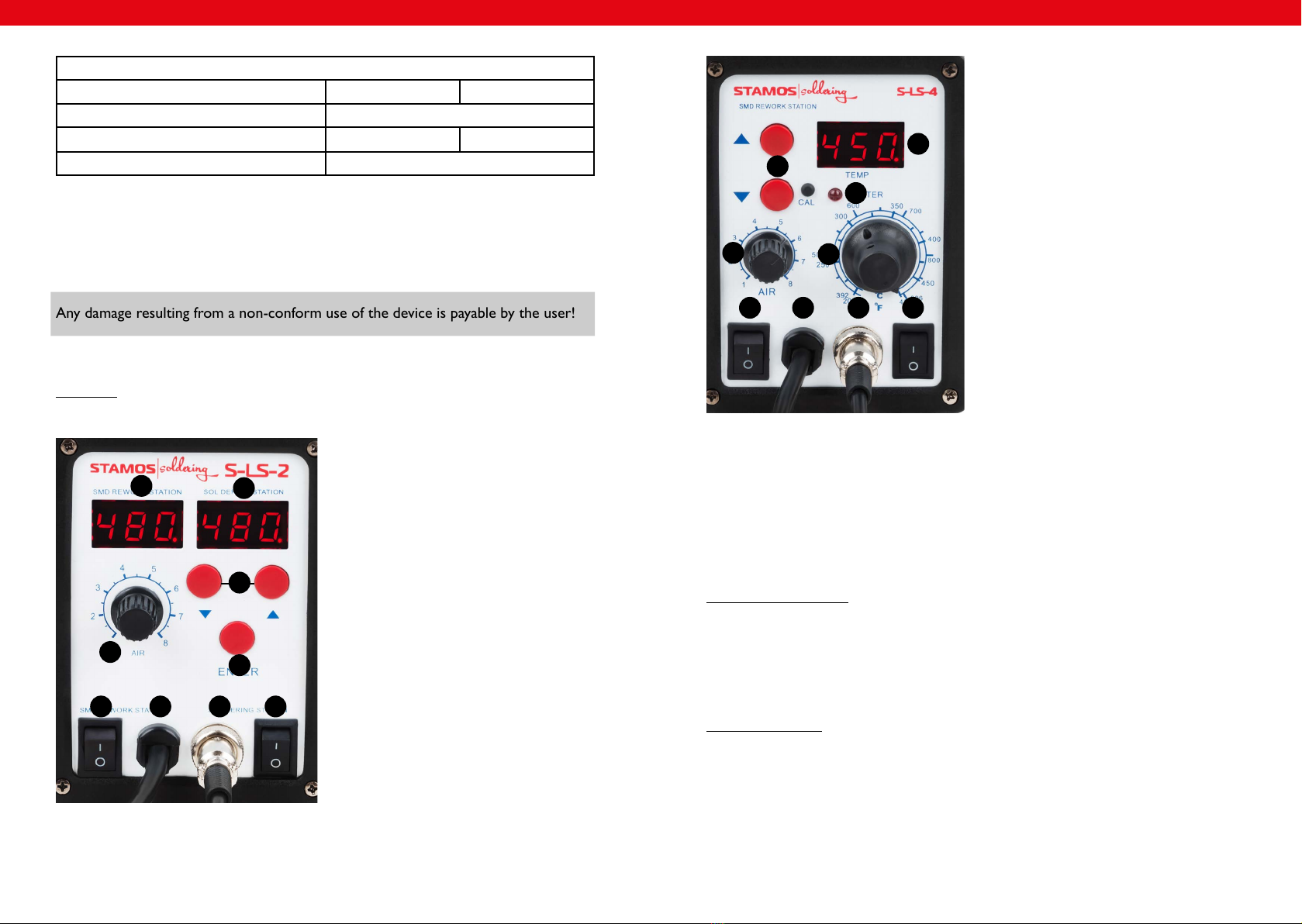
BEDIENUNG DER HEISSLUFT-ENTLÖTSTATION 6103: S-LS-4
1. Das Gerät auf einer stabilen Unterlage anbringen; den Heißluft-Entlöter in der
Halterung unterbringen.
2. Das Netzkabel zur Stromversorgung des Gerätes anschließen; die entsprechende
Düse am Heißluft-Entlöter anbringen.
3. Das Gerät mit dem Hauptschalter, der sich an der Rückseite des Gerätes selbst
bendet, verbinden, den Heißluft-Entlöter mit Schalter (1) verbinden, anschlie-
ßend beginnt der Heißluft-Entlöter sich zu erhitzen.
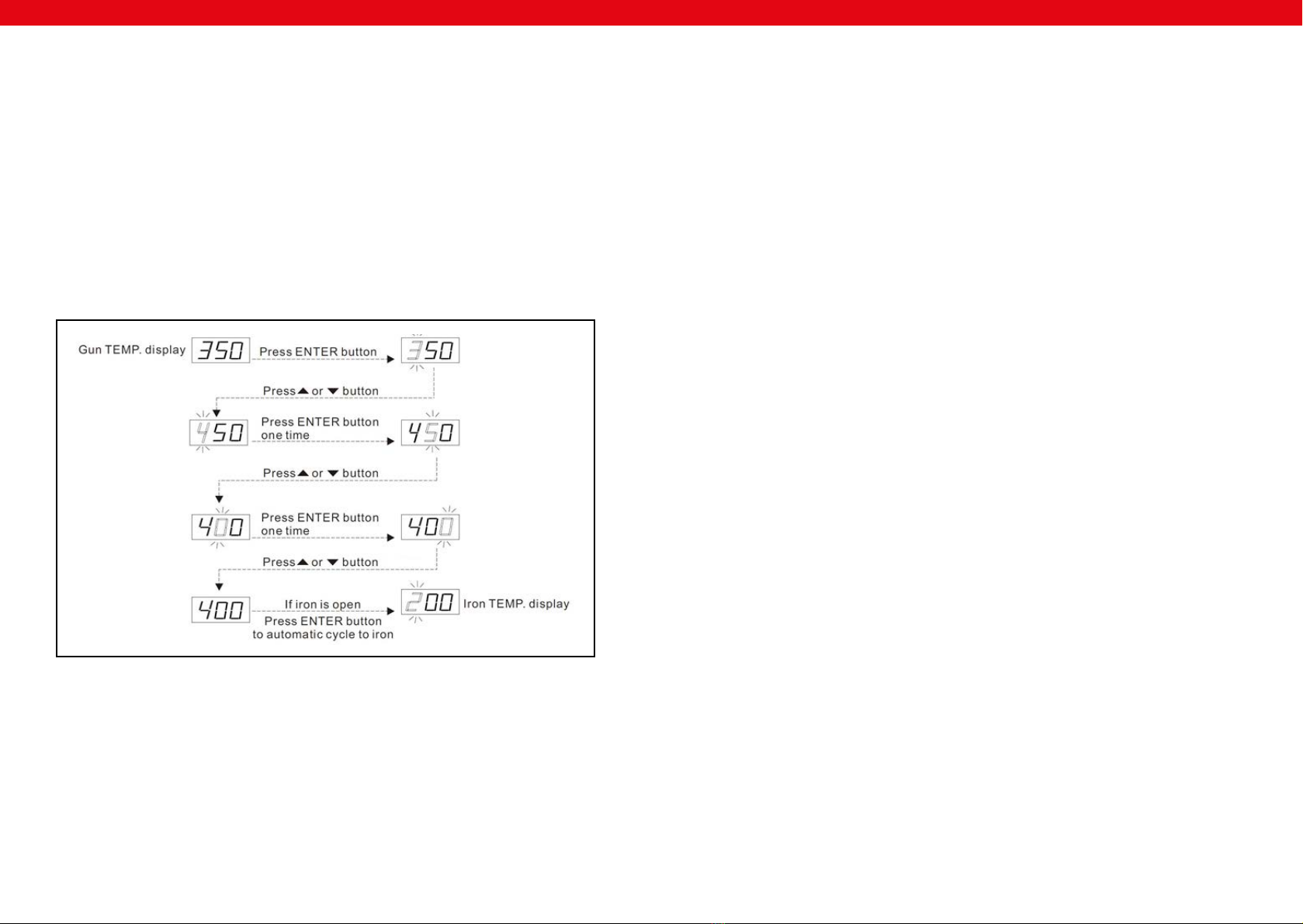
4. Die Temperatur über die Knöpfe (8) einstellen.
5. Einstellung der Luftzufuhr: Die gewünschte Luftzufuhr mithilfe des Luftmengenre-
gulators (9) einstellen.
6. Nach abgeschlossener Arbeit den Heißluft-Entlöter in der Halterung unterbrin-
gen und über den Schalter (1) ausschalten.
7. Wenn das Gerät über einen längeren Zeitraum nicht verwendet wird, sollte es
von der Stromversorgung getrennt werden.
BEDIENUNG DER LÖTSTATION 6103: S-LS-4
1. Das Gerät auf einer stabilen Unterlage anbringen; den Lötkolben in der Halte-
rung unterbringen.
2. Das Netzkabel zur Stromversorgung des Gerätes anschließen; die entsprechende
Spitze am Lötkolben anbringen.
3. Das Gerät mit dem Hauptschalter, der sich an der Rückseite des Gerätes selbst
bendet, verbinden und den Lötkolben mit Schalter (4) verbinden; der Lötkolben
beginnt, sich zu erwärmen.
4. Die gewünschte Temperatur mit Knopf (5) einstellen. Die Anzeige (6) leuchtet
nun auf.Wenn die Anzeige anfängt, regelmäßig zu pulsieren, bedeutet dies, dass
der Lötkolben die zum Arbeitseinsatz entsprechende Temperatur erreicht hat.
5. Nach abgeschlossener Arbeit den Lötkolben in der Halterung unterbringen und
über den Schalter (4) ausschalten.
6. Wenn das Gerät über einen längeren Zeitraum nicht verwendet wird, sollte es
von der Stromversorgung getrennt werden.
ALLGEMEINE ANMERKUNGEN
1. Wenn das Display „---” anzeigt bedeutet dies, dass die Ausgangstemperatur unter
100 ⁰C liegt und die Heißluft-Entlötstation sich im Modus „STAND BY” bendet.
Der Heißluft-Entlöter bendet sich in der Halterung.
2. Wenn das Display „S-E”, bedeutet dies, dass der Lötkolben nicht angeschlossen
ist; es kann sein, dass bei der Heißluft-Entlötstation ein Problem mit dem Sensor
vorliegt.
3. Beim Einschalten des Gerätes müssen sich beide Kolben in der jeweiligen Halte-
rung benden.
4. Man muss sicher gehen, dass die Spitze des Lötkolbens sauber ist und keine Hin-
dernisse oder Blockaden aufweist.
5. Während der Nutzung kleinerer Düsen ist daran zu denken, dass die Luftzufuhr
der montierten Düse entspricht, sowie, um zu vermeiden, dass der Heißluft-Ent-
lötstation beschädigt wird, dass keine zu hohe Luftzufuhr zusammen mit zu hoher
Temperatur über einen zu langen Zeitraum stattndet.
6. Je nach den Erwartungen des Benutzers können verschiedene Einstellungen des
Luftdurchlaufs geringfügigeTemperaturunterschiede hervorrufen. Der minimale
Abstand zwischen der Spitze der Heißluft-Entlötstation und dem zu bearbeiten-
den Gegenstand beträgt 2 mm.
7. Bitte eine gute Luftzufuhr in den Räumen sichern, in welchen das Gerät verwen-
det wird. Darüber hinaus sollte dieses an einem gut belüfteten Ort unterge-
bracht werden, damit die Abfuhr von Wärme gewährleistet wird.
SICHERHEITSHINWEISE
1. Die Düsen dürfen nicht unter Kraftanwendung installiert werden. Hierzu keine
Zangen oder Pinzetten benutzen.
2. Die Düsen und die Endstücke erst auswechseln, wenn sie vollkommen erkaltet
sind.
3. Es ist untersagt, das Gerät in der Nähe leicht entzündbarer Gase, Bestandteile
oder vergleichbarer Substanzen einzusetzen. Die Düsen und die Kolben wie auch
die der Heißluft-Entlötstation entströmende Luft haben eine sehr hohe Tempe-
ratur. Berühren, genauso wie das direkte Ausrichten auf den Körper und das Ge-
sicht, sind untersagt, daVerbrennungen eintreten können.
4. Nach längerem Einsatz der Heißluft-Entlötstation kann sich am Endstück Staub
ansetzen. Dieser ist regelmäßig zu entfernen, damit die Luftdurchlässigkeit nicht
beeinträchtigt wird.
5. Eine zu hohe Arbeitstemperatur des Lötkolbens kann die Funktionsfähigkeit der
Endstücke beeinträchtigen.
6. Die Lötspitze muss regelmäßig mithilfe eines Schwammes oder mit Flussmitteln
gereinigt werden, um das Oxidieren der Spitze zu vermeiden.
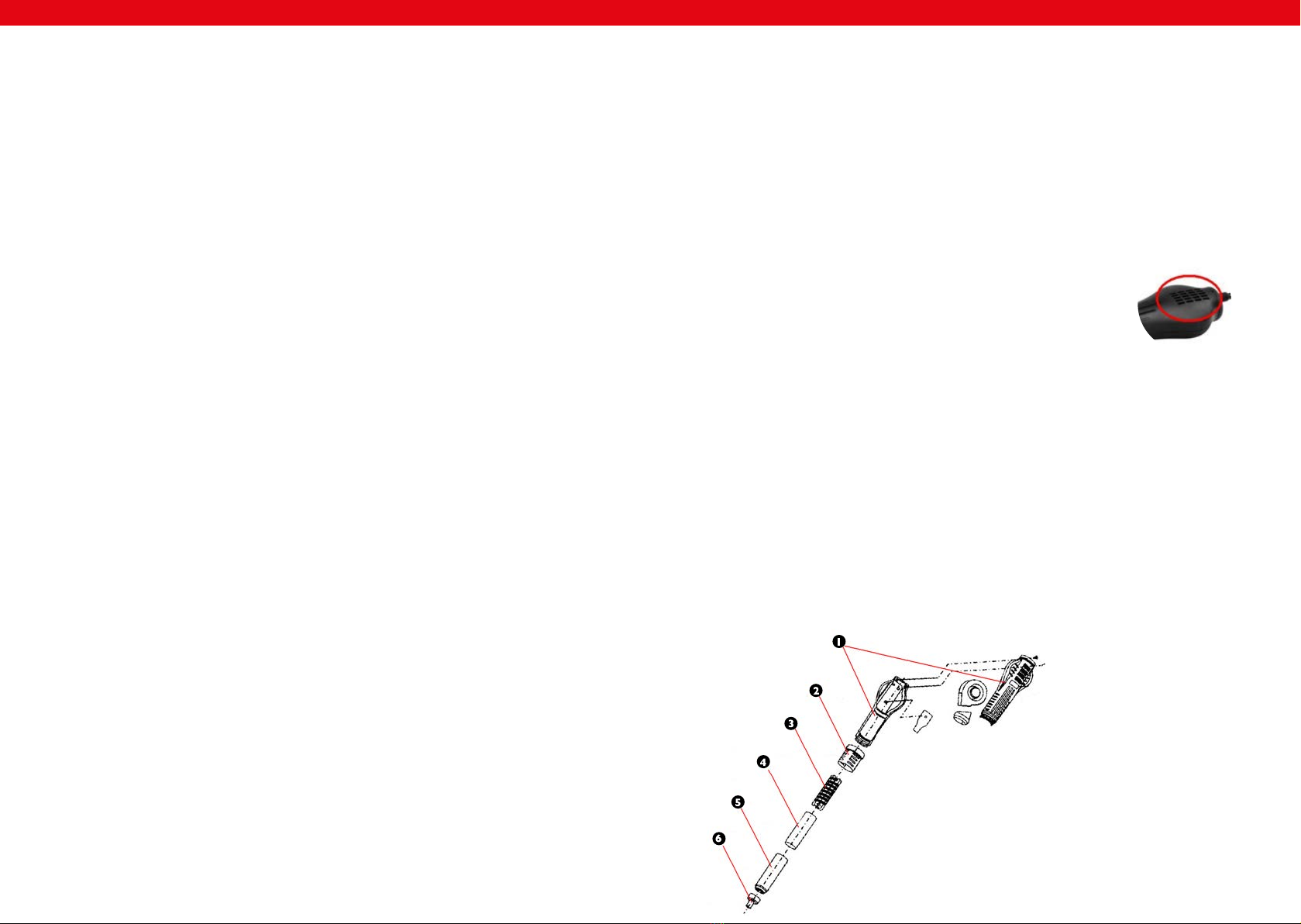
1. Gehäuse der Heißluft-Entlötstation
2. Griffelement
3. Heizelement
4. Abschirmung des Heizelements
5. Ablassröhre
6. Düse
8
ACHTUNG:Verdecken Sie während des Arbeitens
nicht die Lufteinlässe am Heißluft-Entlöter, dies
kann zu Schäden am Lüfter und der Heizeinheit
führen.
8.

DE
11
DE
10
1. Vor Auswechseln des Heizelementes muss überprüft werden, dass die Heißluft-
Entlötstation vollkommen abgekühlt ist.
2. Die Schrauben von der Abdeckung des Kolbens entfernen.
3. Den Griff (2) lösen die Umfassung des Lötkolbens abnehmen.
4. DenVentilator vorsichtig herausnehmen und die Schrauben, welche die Platte mit
den Leitungen verbindet, vorsichtig herausdrehen.
5. Heizelement von der Plate trennen (hierbei auf dieVerbindung der Leitungen
achten).
6. Heizlement aus der Umfassung herausnehmen, dabei darauf achten, dass die Lei-
tung für die Erdung nicht beschädigt wird.
7. Das neue Heizelement mit MICA umwickeln und in die Umfassung an die ent-
sprechende Stelle zurückschieben.
8. Schließen Sie die Drähte an die Platte entsprechend ihrer ursprünglichenVerbin-
dung an.
9. Den Lötkolben in der umgekehrten Reihenfolge wieder zusammensetzen
1
2
3
4
5
6
7
8
1. Mutter zur Festigung der Lötspitze
2. Gehäuse der Lötspitze
3. Lötspitze
4. Mutter mit Heizplattenkabel
5. Feder
6. Heizelement
7. Platte mit Drähten
8. Handgriff
Austausch der Lötspitze und des Heizelementes stellen Sie sicher, dass der Lötkolben
völlig erkaltet ist.
1. Austausch der Lötspitze: Entfernen Sie die Mutter, die die Abdeckung der Lötspit-
ze sichert und entfernen Sie die Abdeckung. Ersetzen Sie diese durch eine neue,
Abdeckung aufsetzen und Mutter festdrehen.
2. Austausch des Heizelementes: Die Mutter, welche die Fassung der Lötspitze si-
chert, abschrauben und die Fassung der Lötspitze herausnehmen. Die Fassung,
die das Heizelement (4) sichert, abschrauben und das Heizelement (6) vorsichtig
herausschieben, zusammen mit der Platte mit den Drähten.Austauschen. Dabei
auf dieVerbindung der Drähte achten.
STANDARDREINIGUNG
Allgemeine Anmerkungen
• Spritzen Sie niemals das Gerät ab. Es dürfen bei der Reinigung keinerlei Bürsten
oder Utensilien benutzt werden, welche die Geräteoberäche beschädigen kön-
nen.
• Bevor Sie anfangen zu reinigen, trennen Sie das Gerät von der Stromversorgung.
REGELMÄSSIGE PRÜFUNG DES GERÄTES
Prüfen Sie regelmäßig, ob Elemente des Gerätes Beschädigungen aufweisen. Sollte dies
der Fall sein, wenden Sie sich an IhrenVerkäufer, um Nachbesserungen vorzunehmen.
Was tun im Probl emfall?
Kontaktieren Sie IhrenVerkäufer und bereiten Sie folgende Angaben vor:
• Rechnungs- und Seriennummer (letztere nden Sie auf dem Typenschild)
• Ggf. ein Foto des defekten Teils
• Ihr Servicemitarbeiter kann besser eingrenzen, worin das Problem besteht, wenn
Sie es so präzise wie möglich beschreiben. Formulierungen wie z.B. „das Gerät
heizt nicht“ können missverständlich sein, und bedeuten, dass das Gerät zu wenig
oder eben gar nicht heizt. Dies sind aber zwei verschiedene Fehlerursachen!
• Geben Sie stets den Zustand der Leuchten an, da dies die Diagnose erleichtert. Je
detaillierter Ihre Angaben sind, umso schneller kann Ihnen geholfen werden!
ACHTUNG: Öffnen Sie niemals das Gerät ohne Rücksprache mit dem Kundenser-
vice. Dies kann Ihren Gewährleistungsanspruch beeinträchtigen!

12
EN
13
CAUTIONS
General safety information for the use of electrical devices:
To avoid injury from re or electric shock, please ensure compliance with safety
instructions when using this device. Please read the instruction carefully and make
sure that you have understood it well. Keep the manual near the equipment to be
able to read it at any time.Always use current sources connected to the ground and
providing the necessary voltage (indicated on the label on the device). If you have any
doubt, let an electrician check that your outlet is properly grounded. Never use a da-
maged power cable. Do not open the unit in damp or wet environment, or if you are
wet yourself. Protect the unit of solar radiation. Use the device in a protected locati-
on to avoid damaging the equipment or endangering others. Make sure the device is
able to cool and avoid placing it too close to other devices that produce heat. Before
cleaning, disconnect it. Use a soft damp cloth for cleaning.Avoid using detergent and
make sure that no liquid enters the unit. No internal element of this device needs to
be maintained by the user.An opening of the device without our approval leads to a
loss of warranty.
General safety information for the use of the device:
• The user manual should be kept close to the device and should always be acces-
sible for the users. Instruct your employees how to use the device properly.
• Make sure the hot air can circulate well and place the device more than10 cm
away from walls and other electrical devices.Aerate well the working area.
• Do not place the device close to combustible materials.
• It may happen that by rst use, the heating element produces a light smoke. This
is absolutely normal. Simply check that the smoke can evaporate and that a good
aeration is provided.
• Some parts of the device can get extremely hot.To avoid any injuries, be careful
by every contact with the device.
• Clean the device regularly to avoid a durable encrustation of dirt.
TECHCNICAL DETAILS
Model 6101 S-LS-2 6103 S-LS-4
Voltage (V) 230~50Hz
Rated current (A) 6
Power (W) 700
Work temperature (⁰C) 0/+40
Storage temperature (⁰C) -20/-80
Storage humidity 35% / 45%
SOLDERING IRON
Temperature range (⁰C) 200-480
Output power (W) 60
Temperature Stability ±1⁰C ±2⁰C
EN

EN
14
SMD REWORK STATION
Temperature range (⁰C) 100-480 100-450
Output power (W) 650
Temperature Stability ±1⁰C ±2⁰C/±1⁰C
Airow (L/min) 120
USAGE PURPOSE
The device is designed for:
1. Different kind of soldering, de-soldering of the electronic components such as:
SOIC, CHIP, QFP, PLCC, BGA, SMD, etc.
2. Shrinking, paint drying, adhesive removal, thawing, warming, plastic welding.
Any damage resulting from a non-conform use of the device is payable by the user!
PRINCIPLE OF OPERATION
Assembly:
6101| S-LS-2:
1. on/off switch of the SMD rework station
2. SMD rework gun cable
3. soldering iron connection socket
4. on / off switch of the soldering station
5. function button
6. buttons for the temperature setting
7. soldering iron temperature display
8. SMD rework gun temperature display
9. airow volume adjustment knob
EN
15
1. on / off switch of the SMD rework station
2. SMD rework gun cable
3. soldering iron connection socket
4. on / off switch of the soldering station
5. soldering iron temperature setting knob
6. soldering iron heater indicator
7. SMD rework gun temperature display
8. buttons for the temperature setting
9. airow volume adjustment knob
BEFORE FIRST USE
Upon receipt of the goods,check the packaging for integrity and open it.If the packaging
is damaged, please contact your transport company and distributor within 3 days, and
document the damages as detailed as possible. Do not turn the package upside down!
When transporting the package, please ensure that it is kept horizontal and stable. Ple-
ase keep all packaging materials (cardboard,plastic tapes and styrofoam),so that in case
of a problem, the device can be sent back to the service centre in accurate condition.
Disposing of packaging
The various items used for packaging (cardboard, plastic straps, polyurethane foam)
should be conserved, so that the device can be sent back to the service center in best
conditions in case of problem!
INSTALLING THE APPLIANCE
Appliance location
The work surface where the device will be located must be suitable for the size of the
appliance, please refer to the measurements. The work surface must be levelled, dry,
heat-resistant and at a tting height from the ground to enable a proper use of the
device.
The power cord connected to the appliance must be properly grounded and corres-
pond to the technical details.
5
41 2 3
9
87
6
8
9
1 2 3 4
5
6
7

EN
16
SMD REWORK STATION 6101 | S-LS-2 OPERATION:
1. Device must be placed on stable work table, SMD rework gun must be placed
into the holder.
2. Fix the appropriate nozzle and connect the device to the power source.
3. Turn on the device with the main switch placed at the back of the device, turn on
the SMD rework gun with switch (1), gun will start to heat.
4. Press ENTER button, rst digit on the SMD rework station temperature display
will start blinking. Using buttons (6) set the desired value, then press ENTER but-
ton again, second digit on the display will start blinking.Again, using buttons (6)
set the desired value and press again ENTER button – third digit on the display
will start blinking – using buttons (6) set the desired value. If the soldering iron
is turned on, press the ENTER button again and rst digit on the soldering iron
temperature display will start blinking. Further temperature setting procedure is
the same as for the SMD rework gun:
5. Setting the desired airow volume: set the desired airow volume using airow
volume adjustment knob.
6. After work, the SMD rework gun should be placed into the holder.Turn off the
SMD rework by switch (1).
7. If the device is not used for a long time, it should be completely disconnected
from the power source.
17
SOLDERING STATION 6101 | S-LS-2 OPERATION:
1. Device must be placed on stable work table, soldering iron must be placed into
the holder.
2. Fix the appropriate soldering tip and connect the device to the power source.
3. Turn on the device with the main switch placed at the back of the device, turn on
the soldering iron with switch (4), it will start to heat.
4. Temperature setting procedure is the same as for the SMD rework temperature
setting described above.
5. After work, the soldering iron should be placed into the holder.Turn off the sol-
dering station by switch (4).
6. If the device is not used for a long time, it should be completely disconnected
from the power source.
6103: S-LS-4
SMD REWORK STATION 6103: S-LS-4 OPERATION:
1. Device must be placed on stable work table, SMD rework gun must be placed
into the holder.
2. Fix the appropriate nozzle and connect the device to the power source.
3. Turn on the device with the main switch placed at the back of the device, turn on
the SMD rework gun with switch (1), gun will start to heat.
4. Set the desired temperature using buttons (8).
5. Setting the desired airow volume: set the desired airow volume using airow
volume adjustment knob.
6. After work, the SMD rework gun should be placed into the holder.Turn off the
SMD rework by switch (1).
7. If the device is not using for a long time, it should be completely disconnected
from the power source.
SOLDERING STATION 6103: S-LS-4 OPERATION:
1. Device must be placed on stable work table, soldering iron must be placed into
the holder.
2. Fix the appropriate soldering tip and connect the device to the power source.
3. Turn on the device with the main switch placed at the back of the device, turn on
the soldering iron with switch (4), it will start to heat.
4. Set the desired temperature using temperature adjustment knob (5). Soldering
iron heater indicator (6) will light up. When the indicator will be ashing regularly,
the desired temperature has been reached and it is constant, and the soldering
iron is ready to work.
5. After work, the soldering iron should be placed into the holder.Turn off the sol-
dering station by switch (4).
6. If the device is not used for a long time, it should be completely disconnected
from the power source.
EN

DE
19
EN
18
GENERAL REMARKS
1. If the display is showing the „---„ it means that the output temperature is lower
than 100 ⁰C, SMD rework station is in stand by mode, SMD rework gun is placed
in the holder.
2. if the display is showing “S-E” it means that soldering iron is disconnected, and
HOT AIR gun is having problem with the heat sensor.
3. When the device is being turned on, both soldering iron and HOT AIR gun should
be placed in their holders.
4. The outlet of the SMD rework gun should be clean and free from any obstacles.
5. When using small nozzles, it should be remembered that the air ow should be
suitable to the diameter of the xed nozzle. In order to avoid any SMD rework
gun damages, too high air ow along with the high temperature mustn’t be used
for a long period of time.
6. Depending on user’s needs, different air ow settings may cause slight variations
in temperatures value.The minimum distance between the outlet of the HOT AIR
gun and the subject is 2 mm.
7. Good ventilation of the room in which the appliance is used must be provided.
In addition, the device should be placed in a location with good air circulation to
dissipate heat.
8. NOTE: It is forbidden to cover the air intake holes on the handle of a SMD
rework gun during work.This may cause serious damages of the fan and the hea-
ter!
SAFETY ISSUES REMARKS
1. Nozzles should be installed without the use of excessive force, also do not use the
pliers or tweezers. Do not over tighten the mounting screws of the nozzle.
2. Tips and nozzles can be changed when the SMD rework gun and the soldering iron
are completely cold.
3. It is forbidden to use the device near the ammable or combustible elements and
objects or at similar places.Tips and nozzles as well as the air coming out of the
HOT AIR gun have very high temperature, it is forbidden to touch these elements
as well as it is forbidden to put the hot air directly to face or body.This can cause
serious burns.
4. After long time of use, the outlet of SMD rework gun may be covered with some
dust.The outlet should be cleaned on a regular basis in order to ensure undistur-
bed air ow.
5. Too high temperature of the soldering iron may be the cause of reduction of the
functionality of the soldering tips.
6. Soldering iron tip must be cleaned regularly using sponge and plate on a layer of tin
to prevent tips oxidation.
REPLACEMENT OF HOT AIR REWORK HEATING ELEMENT
1. HOT AIR gun covers
2. element of the handle
3. heater
4. heater cover
5. outlet pipe
6. nozzle
1. Before heater replacement make sure that the HOT AIR gun is completely cold.
2. Remove the screws in the gun covers.
3. Unscrew the element of the handle (2) and take off the gun covers.
4. Gently remove the fan and remove the wire board screws.
5. Disconnect the heater from the wire board (pay attention to the wires connection
order).
6. Remove the heater from the housing, pay attention to the steel grounding wire.
7. New heater should be wrapped with new mica paper and then it should be placed
inside the housing.
8. Connect the wires to the board in accordance with their original connection me-
thod.
9. Fix the gun in reverse order.
1
2
3
4
5
6
EN

DE
21
EN
REGULAR CLEANING
Generalities
• Never clean the device with a pressurized water-jet, industrial cleaners, and brushes
or any other type of cleaning utensil that could damage the surface of the appliance.
• Before cleaning you must remove the electricity supply plug isolating the appliance
from the main power circuit.
REGULAR CONTROL OF THE DEVICE
Control regularly that the device doesn´t present any damage. If it should be the case,
please contact your customer service to solve the problem.
What to do in case of problem?
Please contact your customer service and prepare following information:
• Invoice number and serial number (the latest is to be found on the technical pla-
te on the device).
• If relevant, a picture of the damaged, broken or defective part.
• It will be easier for your customer service clerk to determinate the source of
the problem if you make a detailed and precise description of the matter.Avoid
formulations like “the device doesn´t heat”, which may mean that it doesn´t heat
enough or even not at all.Though, those two possibilities have a different causati-
on!
The more detailed your information, the quicker the customer service will be able to
answer your problem rapidly and efciently!
CAUTION: Never open the device without the authorization of your customer ser-
vice.This can lead to a loss of warranty!
REPLACEMENT OF THE SOLDERING IRON TIP AND SOLDERING
IRON HEATING CORE ELEMENT
1. nut for mounting the soldering iron tip housing
2. soldering iron tip housing
3. soldering iron tip
4. plastic nut for mounting the heater and the board wires
5. spring
6. heater
7. wires board
8. handle
Before heater replacement make sure that the soldering iron is completely cold.
1. SOLDERING IRON TIP REPLACEMENT: remove the nut for mounting the solde-
ring iron tip housing and take off the housing. Replace the tip with the new one,
place the housing and x all with the plastic nut.
2. HEATER REPLACEMENT: remove the nut for mounting the soldering iron tip
housing and take off the housing along with the tip. Remove the nut for xing the
heater (4) and gently remove the heater (6) along with the board with wires (7).
Replace the whole remembering the wires connection order.
1
2
3
4
5
6
7
8
EN
20

DE
22
PL
PL
ZALECENIA ODNOŚNIE BEZPIECZEŃSTWA
Ogólne zalecenia odnośnie bezpieczeństwa podczas użytkowania urządzeń elektrycz-
nych:
W celu zminimalizowania ryzyka obrażeń na skutek działania ognia lub porażenia
prądem prosimy Państwa o stałe przestrzeganie kilku podstawowych zasad bezpie-
czeństwa podczas użytkowania urządzenia. Prosimy o staranne przeczytanie niniejszej
instrukcji użytkowania i upewnienie się, że znaleźli Państwo odpowiedzi na wszystkie
pytania dotyczące tego urządzenia. Prosimy o staranne przechowywanie niniejszej in-
strukcji użytkowania w pobliżu produktu, aby w razie pojawienia się pytań można było
do niej jeszcze raz powrócić również w późniejszym czasie. Prosimy zawsze stosować
uziemione przyłącze prądu z prawidłowym napięciem sieciowym (patrz instrukcja lub
tabliczka znamionowa)! W razie wątpliwości w odniesieniu do tego, czy przyłącze jest
uziemione, prosimy zlecić sprawdzenie tego wykwalikowanemu specjaliście. Nigdy
nie należy stosować niesprawnego kabla zasilania! Urządzenia nie należy otwierać
w wilgotnym lub mokrym miejscu ani też mokrymi lub wilgotnymi rękoma. Poza
tym urządzenie należy chronić przed bezpośrednim promieniowaniem słonecznym.
Urządzenie należy użytkować zawsze w bezpiecznym miejscu, tak aby nikt nie mógł
nadepnąć na kabel, przewrócić się o niego i/lub uszkodzić go. Przed przystąpieniem do
czyszczenia urządzenia należy wyciągnąć wtyczkę sieciową, a do czyszczenia używać
jedynie wilgotnej ściereczki. Należy unikać stosowania środków czyszczących i uwa-
żać, aby jakakolwiek ciecz nie dostała się do urządzenia i/lub tam nie pozostała.
Należy wyłączyć urządzenie natychmiast po zauważeniu nieprawidłowości w sposobie
jego funkcjonowania. Powinno się również wyciągnąć wtyczkę z gniazdka sieciowego,
gdy urządzenie nie jest używane. Wykonanie prac związanych z konserwacją, wyre-
gulowaniem i naprawą urządzenia należy zlecić wyspecjalizowanemu personelowi. W
przypadku napraw dokonywanych przez osoby trzecie gwarancja wygasa!
Ogólne zalecenia odnośnie użytkowania
• Należy sporządzić i udostępnić instrukcję eksploatacji i przeszkolić osoby zatrud-
nione w zakresie zgodnego z przeznaczeniem obchodzenia się. Instrukcja eksplo-
atacji musi być stale dostępna w miejscu eksploatacji urządzenia.
• Należy zapewnić wystarczającą cyrkulację powietrza. W tym celu urządzenie
należy ustawić z zachowaniem odstępu powyżej 10cm od ściany lub innych urzą-
dzeń oraz zadbać o wystarczającą wentylację w pomieszczeniu, w którym jest
ono użytkowane.
• Należy upewnić się, że w pobliżu urządzenia nie znajdują się jakiekolwiek zapalne
substancje lub przedmioty.
• W niektórych przypadkach podczas pierwszego użycia z wnętrza urządzenia
może wydobywać się dym z elementów grzejnych. Jest to zjawisko całkowicie
normalne. Należy zadbać jedynie o odpowiednią wentylację.
• Niektóre elementy urządzenia mogą się bardzo nagrzewać. W celu uniknięcia ob-
rażeń należy zachować ostrożność podczas dotykania tych powierzchni.
• Należy regularnie czyścić urządzenie, aby nie dopuścić do trwałego osadzenia się
zanieczyszczeń.
23

PL PL
Modell 6101 S-LS-2 6103 S-LS-4
Napięcie (V) 230~50Hz
Prąd znamionowy (A) 6
Moc (W) 700
Temperatura pracy (⁰C) 0/+40
Temperatura składowania (⁰C) -20/-80
Wilgotność składowania 35% / 45%
STACJA LUTOWNICZA
Zakres temperatury (⁰C) 200-480
Moc wyjściowa (W) 60
Stabilność temperatury 1⁰C 2⁰C
STACJA HOT AIR
Zakres temperatury (⁰C) 100-480 100-450
Moc wyjściowa (W) 650
Stabilność temperatury ±1⁰C ±2°C/±1⁰C
Prędkość przepływu powietrza (L/min) 120
OBSZAR ZASTOSOWANIA
Urządzenie przeznaczone jest do:
1. Różnego rodzaju lutowania lub rozlutowywania elementów elektronicznych, takie
jak: SOIC, CHIP, QFP, PLCC, BGA, SMD, itp.
2. Obkurczania, suszenia farb, usuwania klejów, rozmrażania, ocieplania, spawania two-
rzyw sztucznych.
Odpowiedzialność za wszelkie szkody powstałe w wyniku użytkowania niezgodnego z
przeznaczeniem ponosi użytkownik.
KARTA DANYCH TECHNICZNYCH
JAK FUNKCJONUJE URZĄDZENIE – PODSTAWOWA ZASADA
Budowa urządzenia:
6101: S-LS-2:
1. włącznik stacji hot air
2. przewód kolby hot air
3. gniazdo podłączenia kolby lutowniczej
4. włącznik stacji lutowniczej
5. przycisk funkcyjny
6. przyciski ustawiania temperatury
7. wyświetlacz temperatury stacji lutowniczej
8. wyświetlacz temperatury stacji hot air
9. pokrętło regulacji ilości przepływu powietrza
5
41 2 3
9
87
6
8
9
1 2 3 4
5
6
7
6103: S-LS-4:
1. włącznik stacji hot air
2. przewód kolby hot air
3. gniazdo podłączenia kolby lutowniczej
4. włącznik stacji lutowniczej
5. pokrętło regulacji temperatury kolby
lutowniczej
6. wskaźnik pracy grzałki kolby lutowni-
czej
7. wyświetlacz temperatury stacji hot air
8. przyciski ustawiania temperatury stacji
hot air
9. pokrętło regulacji ilości przepływu po-
wietrza
24 25

PL
PRZED PIERWSZYM UŻYCIEM
Kontrola po otrzymaniu towaru
W momencie otrzymania towaru należy sprawdzić opakowanie pod kątem występo-
wania ewentualnych uszkodzeń i otworzyć je. Jeżeli opakowanie jest uszkodzone pro-
simy o skontaktowanie się w przeciągu 3 dni z przedsiębiorstwem transportowym lub
Państwa dystrybutorem oraz o udokumentowanie uszkodzeń w jak najlepszy sposób.
Prosimy nie stawiać pełnego opakowania do góry nogami! Jeżeli opakowanie będzie
ponownie transportowane prosimy zadbać o to, by było ono przewożone w pozycji
poziomej i by było stabilne ustawione.
Utylizacja opakowania
Prosimy o zachowanie elementów opakowania (tektury, plastykowych taśm oraz sty-
ropianu), aby w razie konieczności oddania urządzenia do serwisu można go było jak
najlepiej ochronić na czas przesyłki!
MONTAŻ URZĄDZENIA
Umiejscowienie urządzenia
Urządzenie powinno się ustawić na powierzchni roboczej, która pod względem wy-
miarów będzie co najmniej odpowiadała wymiarom urządzenia. W celu umożliwienia
optymalnej pracy urządzenia powierzchnia robocza powinna być prosta, sucha, mieć
odpowiednią wysokość i być odporna na działanie ciepła.
Należy pamiętać o tym, by zasilanie urządzenia energią odpowiadało danym podanym
na tabliczce znamionowej!
OBSŁUGA STACJI HOT AIR 6101: S-LS-2
1. Urządzenie należy umieścić na stabilnym podłożu, kolbę hot air należy umieścić w
uchwycie.
2. Podłączyć przewód zasilający urządzenie, zainstalować odpowiednią dyszę w kol-
bie.
3. Włączyć urządzenie włącznikiem głównym znajdującym się z tyłu urządzenia, włą-
czyć kolbę hot air włącznikiem (1), kolba zacznie się nagrzewać.
4. Wcisnąć przycisk „ENTER”, pierwsza cyfra na wyświetlaczu temperatury stacji
hot air zacznie migać. Przyciskami (6) ustawić żądaną wartość, następnie wci-
snąć ponownie przycisk „ENTER”, druga cyfra na wyświetlaczu zacznie migać.
Przyciskami (6) ustawić żądaną wartość, następnie wcisnąć ponownie przycisk
„ENTER” trzecia cyfra na wyświetlaczu zacznie migać - przyciskami (6) ustawić
żądaną wartość. Jeśli kolba lutownicza jest włączona, kolejne wciśnięcie spowodu-
je miganie pierwszej cyfry na wyświetlaczu temperatury kolby lutowniczej. Dalsza
procedura ustawiania temperatury kolby lutowniczej jest taka sama jak dla kolby
hot air:
PL
5. Ustawienie przepływu powietrza: ustawić żądany przepływ pokrętłem regulacji
ilości przepływu powietrza.
6. Po skończonej pracy, kolbę HOT AIR należy umieścić w uchwycie i wyłączyć ją
wyłącznikiem (1).
7. W przypadku gdy urządzenie nie jest używane przez długi okres czasu należy
odłączyć je od zasilania.
OBSŁUGA STACJI LUTOWNICZEJ 6101: S-LS-2
1. Urządzenie należy umieścić na stabilnym podłożu, kolbę lutowniczą należy umie-
ścić w uchwycie.
2. Podłączyć przewód zasilający urządzenie, zainstalować odpowiednią końcówkę
lutowniczą w kolbie.
3. Włączyć urządzenie włącznikiem głównym znajdującym się z tyłu urządzenia, włą-
czyć kolbę lutowniczą włącznikiem (4), kolba zacznie się nagrzewać.
4. Ustawienie temperatury jest analogiczne do ustawienia temperatury stacji HOT
AIR opisanym powyżej.
5. Po skończonej pracy, kolbę lutowniczą należy umieścić w uchwycie i wyłączyć ją
wyłącznikiem (4).
6. W przypadku gdy urządzenie nie jest używane przez długi okres czasu należy
odłączyć je od zasilania.
OBSŁUGA STACJI HOT AIR 6103: S-LS-4
1. Urządzenie należy umieścić na stabilnym podłożu, kolbę hot air należy umieścić w
uchwycie.
2. Podłączyć przewód zasilający urządzenie, zainstalować odpowiednią dyszę w kol-
bie.
26 27

DEPL
1. obudowa kolby hot air
2. element uchwytu
3. grzałka
4. osłona grzałki
5. rurka wylotowa
6. dysza
PL
3. Włączyć urządzenie włącznikiem głównym znajdującym się z tyłu urządzenia, włą-
czyć kolbę hot air włącznikiem (1), kolba zacznie się nagrzewać.
4. Ustawić żądaną temperaturę przyciskami (8).
5. Ustawienie przepływu powietrza: ustawić żądany przepływ pokrętłem regulacji
ilości przepływu powietrza (9).
6. Po skończonej pracy, kolbę HOT AIR należy umieścić w uchwycie i wyłączyć ją
wyłącznikiem (1).
7. W przypadku gdy urządzenie nie jest używane przez długi okres czasu należy
odłączyć je od zasilania.
OBSŁUGA STACJI LUTOWNICZEJ 6103: S-LS-4
1. Urządzenie należy umieścić na stabilnym podłożu, kolbę lutowniczą należy umie-
ścić w uchwycie.
2. Podłączyć przewód zasilający urządzenie, zainstalować odpowiednią końcówkę
lutowniczą w kolbie.
3. Włączyć urządzenie włącznikiem głównym znajdującym się z tyłu urządzenia, włą-
czyć kolbę lutowniczą włącznikiem (4), kolba zacznie się nagrzewać.
4. Ustawić żądaną temperaturę pokrętłem (5). Wskaźnik grzania (6) zaświeci się. W
momencie gdy wskaźnik ten zacznie regularnie pulsować, będzie to oznaczać, że
kolba osiągnęła stałą temperaturę i jest gotowa do pracy.
5. Po skończonej pracy, kolbę lutowniczą należy umieścić w uchwycie i wyłączyć ją
wyłącznikiem (4).
6. W przypadku gdy urządzenie nie jest używane przez długi okres czasu należy
odłączyć je od zasilania.
UWAGI OGÓLNE
1. W przypadku gdy wyświetlacz pokazuje „---” oznacza to że temperatura wyjścio-
wa wynosi poniżej 100 ⁰C, stacja hot air jest w trybie czuwania („STAND BY”) a
kolba hot air jest umieszczona w uchwycie.
2. W przypadku gdy wyświetlacz pokazuje „S-E” oznacza to, że kolba lutownicza
jest odłączona; w kolbie hot air występuje problem z czujnikiem.
3. W momencie włączania urządzenia obie kolby muszą znajdować się w odpowied-
nich uchwytach.
4. Należy upewnić się, że wylot kolby hot air jest czysty i nie zawiera żadnych blo-
kad ani przeszkód.
5. Podczas korzystania z małych dysz należy pamiętać o tym aby przepływ powie-
trza był dostosowany do zamontowanej dyszy oraz aby uniknąć uszkodzenia kol-
by hot air nie należy utrzymywać wysokiego przepływu powietrza wraz z wysoką
temperaturą przez zbyt długi okres czasu.
6. W zależności od wymagań użytkownika, różne ustawienia przepływu powietrza
mogą powodować nieznaczne różnice w temperaturze. Minimalna odległość mię-
dzy wylotem kolby hot air a przedmiotem wynosi 2 mm.
7. Należy zapewnić dobra wentylację pomieszczenia w którym urządzenie jest użyt-
kowane. Ponadto urządzenie powinno być umieszczone w miejscu zapewniającym
dobry przepływ powietrza celem odprowadzenia ciepła.
8.
UWAGI ODNOŚNIE BEZPIECZEŃSTWA
1. Dysze należy instalować bez użycia przesadnej siły, nie należy używać do tego
celu obcęgów czy szczypiec. Nie należy zbyt mocno przykręcać śrub mocujących
dyszę.
2. Dysze i końcówki można wymieniać gdy kolby są całkowicie zimne.
3. Zabrania się używania urządzenia w pobliżu elementów, gazów łatwopalnych lub
innych tego typu obiektów. Dysze oraz końcówki kolb jak również powietrze
wydobywające się z kolby hot air mają bardzo wysoką temperaturę, zabrania się
dotykania tych elementów, jak również kierowania strumienia gorącego powie-
trza bezpośredni ona ciało lub twarz. Grozi to poparzeniem.
4. Po długim użytkowaniu kolby hot air, wylot kolby może pokryć się kurzem. Wylot
należy czyścić regularnie aby przepływ powietrza nie był zakłócony.
5. Zbyt wysoka temperatura pracy kolby lutowniczej może zredukować funkcjonal-
ność końcówki lutowniczej.
6. Końcówka lutownicza musi być czyszczona regularnie przy pomocy gąbki i topni-
ka aby zapobiec utlenianiu się końcówki.
WYMIANA ELEMENTU GRZEWCZEGO KOLBY HOT AIR
1. Przed wymianą elementu grzewczego należy się upewnić, że kolba hot air jest cał-
kowicie zimna.
2. Odkręcić śrubki mocujące obudowę kolby.
3. Odkręcić element uchwytu (2) i zdjąć obudowę kolby.
4. Delikatnie zdjąć wentylator i odkręcić śrubki mocujące płytkę z przewodami.
5. Odłączyć grzałkę od płytki (zwrócić uwagę na podłączenie przewodów).
6. Usunąć grzałkę z obudowy, zwrócić uwagę na to by nie uszkodzić metalowego
przewodu uziemiającego.
28 29
UWAGA: Zabrania się zakrywania otworów wlotowych powie-
trza na uchwycie kolby hot air w trakcie jej pracy. Może to dopro-
wadzić do uszkodzenia wentylatora oraz grzałki!

7. Nową grzałkę owinąć papierem mika i wsunąć w obudowę w odpowiednie miej-
sce.
8. Podłączyć przewody do płytki zgodnie z ich pierwotnym podłączeniem.
9. Złożyć kolbę w odwrotnej kolejności.
WYMIANA ELEMENTU GRZEWCZEGO ORAZ KOŃCÓWKI KOLBY
LUTOWNICZEJ
PL
1
2
3
4
5
6
7
8
1. nakrętka mocująca obudowę końcówki lutowniczej
2. obudowa końcówki lutowniczej
3. końcówka lutownicza
4. nakrętka mocująca grzałkę wraz z płytką z przewodami
5. sprężyna
6. grzałka
7. płytka z przewodami
8. uchwyt
Przed wymianą końcówki lutowniczej oraz elementu grzewczego należy się upewnić,
że kolba lutownicza jest całkowicie zimna.
1. WYMIANA KOŃCÓWKI LUTOWNICZEJ: Odkręcić nakrętkę mocującą obu-
dowę końcówki lutowniczej i zdjąć obudowę końcówki. Wymienić końcówkę na
nową, założyć obudowę i skręcić nakrętką.
2. WYMIANA GRZAŁKI: Odkręcić nakrętkę mocującą obudowę końcówki lu-
towniczej i zdjąć obudowę końcówki. Odkręcić nakrętkę mocującą grzałkę (4) i
delikatnie wysunąć grzałkę (6) wraz z płytką z przewodami (7). Wymienić całość
pamiętając o sposobie podłączenia przewodów.
STANDARDOWE CZYSZCZENIE
Uwagi ogólne
• Nigdy nie należy spryskiwać urządzenia. Do czyszczenia nie należy używać jakich-
kolwiek szczotek czy przyborów, które mogłyby uszkodzić powierzchnię urzą-
dzenia.
• Przed rozpoczęciem czyszczenia urządzenie należy odłączyć od źródła zasilania
energią.
REGULARNA KONTROLA URZĄDZENIA
Należy regularnie sprawdzać, czy elementy urządzenia nie są uszkodzone. Jeżeli ele-
menty te będą uszkodzone, to należy zwrócić się do sprzedawcy z prośbą o ich na-
prawę.
Co należy zrobić w przypadku pojawienia się problemu?
Należy skontaktować się ze sprzedawcą i przygotować następujące dane:
• Numer faktury oraz numer seryjny (nr seryjny podany jest na tabliczce znamio-
nowej).
• Ewentualnie zdjęcie niesprawnej części.
• Pracownik serwisu jest w stanie lepiej ocenić, na czym polega problem, jeżeli
opiszą go Państwo w sposób tak precyzyjny, jak jest to tylko możliwe. Sformu-
łowania, takie jak np. „urządzenie nie grzeje“ mogą być dwuznaczne i oznaczają
zarówno, że urządzenie grzeje za słabo lub w ogóle nie grzeje. Są to jednak dwie
różne przyczyny usterek! Im bardziej szczegółowe są dane, tym szybciej można
Państwu pomóc!
UWAGA: Nigdy nie wolno otwierać urządzenia bez konsultacji z serwisem klienta.
Może to prowadzić do utraty gwarancji!
30
PL
31

3332
NOTIZEN | NOTES NOTIZEN | NOTES

3534
NOTIZEN | NOTES
DE
Hiermit bestätigen wir, dass die hier in dieser Anleitung aufgeführten Geräte CE-
konform sind.
EN
We hereby certify that the appliances listed in this manual are CE compliant.
FR
Par la présente, nous conrmons que les appareils présentés dans ce mode d´emploi
sont conformes aux normes Ce.
PL
Niniejszym potwierdzamy, że urządzenia opisane w tej instrukcji są zgodne z
deklaracją CE.

Hersteller an Verbraucher
Sehr geehrte Damen und Herren,
gebrauchte Elektro- und Elektronikgeräte dürfen gemäß europäischer Vorgaben [1] nicht zum unsortierten Siedlungsabfall
gegeben werden, sondern müssen getrennt erfasst werden. Das Symbol der Abfalltonne auf Rädern weist auf die Notwendigkeit
der getrennten Sammlung hin. Helfen auch Sie mit beim Umweltschutz. Sorgen Sie dafür, dieses Gerät, wenn Sie es nicht mehr
weiter nutzen wollen, in die hierfür vorgesehenen Systeme der Getrenntsammlung zu geben.
In Deutschland sind Sie gesetzlich [2] verpichtet, ein Altgerät einer vom unsortierten Siedlungsabfall getrennten Erfassung
zuzuführen. Die öffentlich - rechtlichen Entsorgungsträger (Kommunen) haben hierzu Sammelstellen eingerichtet, an denen
Altgeräte aus privaten Haushalten ihres Gebietes für Sie kostenfrei entgegengenommen werden. Möglicherweise holen die
rechtlichen Entsorgungsträger die Altgeräte auch bei den privaten Haushalten ab.
Bitte informieren Sie sich über Ihren lokalen Abfallkalender oder bei Ihrer Stadt- oder Gemeindeverwaltung über die in Ihrem
Gebiet zur Verfügung stehenden Möglichkeiten der Rückgabe oder Sammlung von Altgeräten.
[1] RICHTLINIE 2002/96/EG DES EUROPÄISCHEN PARLAMENTS UND DES RATES
ÜBER ELEKTRO- UND ELEKTRONIK - ALTGERÄTE
[2] Gesetz über das Inverkehrbringen, die Rücknahme und die umweltverträgliche Entsorgung
von Elektro- und Elektronikgeräten (Elektro- und Elektronikgerätegesetz - ElektroG).
Po zakończeniu okresu użytkowania nie wolno usuwać niniejszego produktu poprzez normalne odpady komunalne, lecz należy
go oddać do punktu zbiórki i recyklingu urządzeń elektrycznych i elektronicznych. Informuje o tym symbol, umieszczony na
produkcie, instrukcji obsługi lub opakowaniu.
Zastosowane w urządzeniu tworzywa nadają się do powtórnego użycia zgodnie z ich oznaczeniem. Dzięki powtórnemu użyciu,
wykorzystaniu materiałów lub innym formom wykorzystania zużytych urządzeń wnoszą Państwo istotny wkład w ochronę
naszego środowiska.
Informacji o właściwym punkcie usuwania zużytych urządzeń udzieli Państwu administracja gminna.
For the disposal of the device please consider and act according to the national and local rules and regulations.
Umwelt- und Entsorgungshinweise
CONTACT
emaks spółka z ograniczoną
odpowiedzialnością sp.k.
Ul. Dekoracyjna 3
65-155 Zielona Góra
Nr. kom.: +48 506 06 05 74
WWW.STAMOS-WELDING.COM
This manual suits for next models
1
Table of contents
Languages:
Other STAMOS Rework Station manuals