(2)
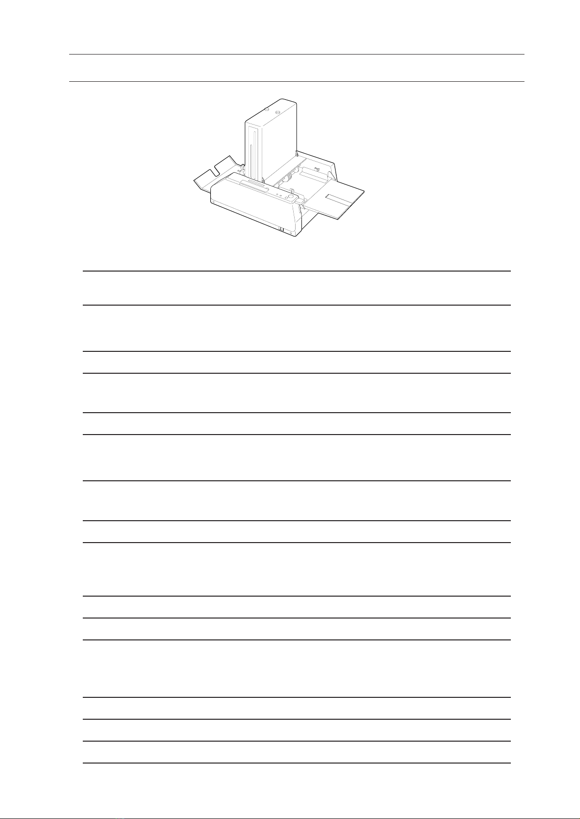
2. Operation Overview
1. Turn on power switch.
1st and 2nd stoppers move to home position
automatically. Then stoppers moves accord-
ing to fold pattern and sheet size memorized
at previous operation. When feed tray lever
rises at that time, motor, fold roller and
delivery belts will rotate. When feed tray
lever lowers, motor does not rotate.
2. Push feed tray lever down.
Motor will stop about 0.5 minute later.
3. Pile sheets into feed tray and select fold
pattern with folding pattern select button.
Stoppers move to set position according to
fold pattern. Deflector is activated only
when single fold pattern is selected.
4. Push feed tray lever up.
Motor will rotate.
5. Press test feed button.
- Clutch will be activated and feed roller
will make 1 turn and a sheet is fed.
- If sheet is not piled on feed tray, motor
will stop.
6. Press start/stop button.
- Clutch will be activated and a sheet will be
fed continuously or sheets will be fed con-
tinuously with some intervals (only accor-
dion fold and short fold).
7. Sheet feeding stops.
- Clutch will be off and only feed roller
stops when start/stop button is pressed.
- Clutch will be off and feed roller stops and
motor stops when feed tray lever is lowered.
- Feed roller stops when counter reaches
input number in the case of preset counter is
used.
- Feed roller stops when sheets run out on
feed tray.
Display Indication
" Please wait"
"Set Delivery Roller"
"0 / 0"
"Set Delivery Roller"
"0 / 0"
"0 / 0"
"0 / 0"
"1 / 0"
"Empty Tray"
"1 / 0"
Count Up
"50 / 0"
"0 / 50 Preset Stop"