Standby L88 User manual

L88 Amber – Manual
WAM488AmberA 1 Standby AB – standbygroup.se
L88 Amber
Thank you for choosing a product from Standby.
Technical Data
Lens Polycarbonate
Housing ABS, plastic (black)
Color Amber
Diodes 4 high power LED
Cable Single: 0.84 m (160 mm + 680 mm) + 2 m driver cable
Double: 2x 0.84 m (160 mm + 680 mm) + 2 m driver cable
Power 10-30 V DC
Ambient temperature -40ºC to +85ºC
Size Lamp: Ø29 x 24.1 mm
Driver (single): 80 x 14.3 x 18.6 mm
Driver (double): 80 x 14 x 27 mm
Approvals Warning light, class 2: ECE R65 (E5)
Indicator: ECE R6
EMC: ECE R10 (E5
Included Single:
1 x L88 Lamp Amber
1 x driver D13s
1 x grommet
1 x E5 label
Double:
2 x L88 Lamp Amber
1 x driver D13d
2 x grommets
2 x E5 labels
Synchronizin
g
Up to 10 lamps (lamps and driver)
Input Active on low flank
Factory Settings
Flash pattern Sync mode
Double Simultaneous
To change the flash pattern setting, see Flash Pattern. To change the sync mode setting, see Sync Mode.

L88 Amber – Manual
WAM488AmberA 2 Standby AB – standbygroup.se
Flash Pattern
Introduction
The flash pattern setting controls the flash pattern. There are five versions of flash pattern: Double,
Triple, Steady burn 1, Steady burn 2 and Indicator.
Double and Triple are built-in flash patterns and no control system is needed.
With Steady burn 1 and Steady burn 2 an external flasher or control system is used to
control the flash pattern.
With Indicator the lamp is controlled by the direction indicator system.
The factory setting of flash pattern is Double.
When in configuration mode, the number of blank flashes (lamp off) in the flash sequence show the
current flash pattern setting, see table.
Blank flashes per
flash sequence Flash pattern Flash control
1 Double Built-in
2 Triple Built-in
3 Steady burn 1 External
4 Steady burn 2 External
5 Indicator Direction indicator system
Setting the Flash Pattern
WARNING
Risk of eye damage. Do not look into the beam at close range.
WARNING
Hot surfaces. Do not touch the cooling flanges when the lamp is on.
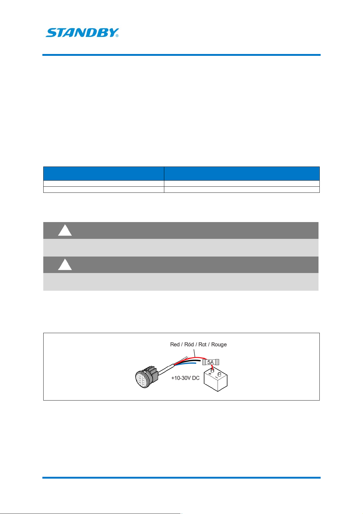
1. If already in configuration mode, go to step 6.
2. If the lamp is connected to the power supply, disconnect it.
3. Connect the red wire to 10-30 V DC via a 5 A fuse.
!
!

L88 Amber – Manual
WAM488AmberA 3 Standby AB – standbygroup.se
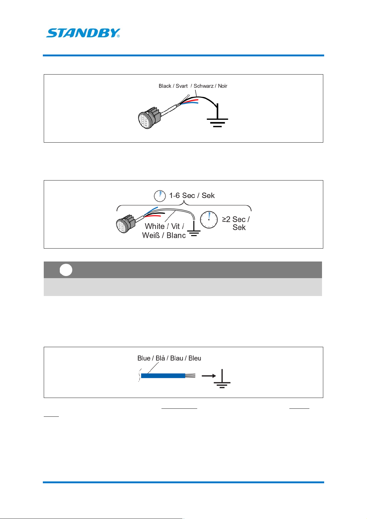
4. Connect the black wire to ground.
5. Within 1 to 6 sec: temporarily connect the white wire to ground and let it stay connected for at
least 2 sec.
The lamp enters configuration mode and a flash sequence indicating the current settings starts.
Note
If this step is performed incorrectly, you must restart from step 2.
6. Count the number of blank flashes (lamp off) per flash sequence to find out the current flash
pattern setting.
7. Temporarily connect the white wire to ground to change to the next version of flash pattern. Each
time the white wire is temporarily connected to ground the next version of flash pattern is selected.
8. To change the sync mode setting, see Sync Mode. To reset to factory settings, see Factory Reset.
9. Disconnect the power supply to save the selected settings and exit configuration mode.
!
L88 Amber – Manual
WAM488AmberA 4 Standby AB – standbygroup.se
Sync Mode
Introduction
The sync mode setting controls how the flashing of two or more lamps is synchronized. There are two
versions of sync mode: Simultaneous and Alternate.
Simultaneous means that the lamps are in sync, that is they come on and go off at the
same time.
Alternate means that the lamps are out of sync.
The factory setting of sync mode is Simultaneous.
When in configuration mode, the number of bright flashes per flash sequence show the current sync
mode setting, see table.
Bright flashes
per flash sequence Sync mode
1 Simultaneous
2 Alternate
Setting the Sync Mode
WARNING
Risk of eye damage. Do not look into the beam at close range.
WARNING
Hot surfaces. Do not touch the cooling flanges when the lamp is on.
1. If already in configuration mode, go to step 6.
2. If the lamp is connected to the power supply, disconnect it.
3. Connect the red wire to 10-30 V DC via a 5 A fuse.
!
!
L88 Amber – Manual
WAM488AmberA 5 Standby AB – standbygroup.se
4. Connect the black wire to ground.
5. Within 1 to 6 sec: temporarily connect the white wire to ground and let it stay connected for at
least 2 sec.
The lamp enters configuration mode and a flash sequence indicating the current settings starts.
Note
If this step is performed incorrectly, you must restart from step 2.
6. Count the number of bright flashes per flash sequence to find out the current sync mode setting.
7. Temporarily connect the blue wire to ground to change to the next version of sync mode. Each time
the blue wire is temporarily connected to ground the next version of sync mode is selected.
8. To change the flash pattern setting, see Flash Pattern. To reset to factory settings, see Factory
Reset.
9. Disconnect the power supply to save the selected settings and exit configuration mode.
!

L88 Amber – Manual
WAM488AmberA 6 Standby AB – standbygroup.se
Factory Reset
Introduction
The settings can be changed back to the factory settings.
The factory settings are the following:
Flash pattern – Double
Sync mode - Simultaneous
Reset to Factory Settings
WARNING
Risk of eye damage. Do not look into the beam at close range.
WARNING
Hot surfaces. Do not touch the cooling flanges when the lamp is on.
Note
All current settings, that is both flash pattern setting and sync mode setting, are reset to the
default settings.
1. If already in configuration mode, go to step 6.
2. If the lamp is connected to the power supply, disconnect it.
3. Connect the red wire to 10-30 V DC via a 5 A fuse.
4. Connect the black wire to ground.
!
!
!

L88 Amber – Manual
WAM488AmberA 7 Standby AB – standbygroup.se
5. Within 1 to 6 sec: temporarily connect the white wire to ground and let it stay connected for at
least 2 sec.
The lamp enters configuration mode and a flash sequence indicating the current settings starts.
Note
If this step is performed incorrectly, you must restart from step 2.
6. Connect the BLUE and the WHITE wire to ground and let them stay connected for at least 2
seconds.
7. The reset is confirmed with a bright steady light for 2-3 seconds.
!
L88 Amber – Manual
WAM488AmberA 8 Standby AB – standbygroup.se
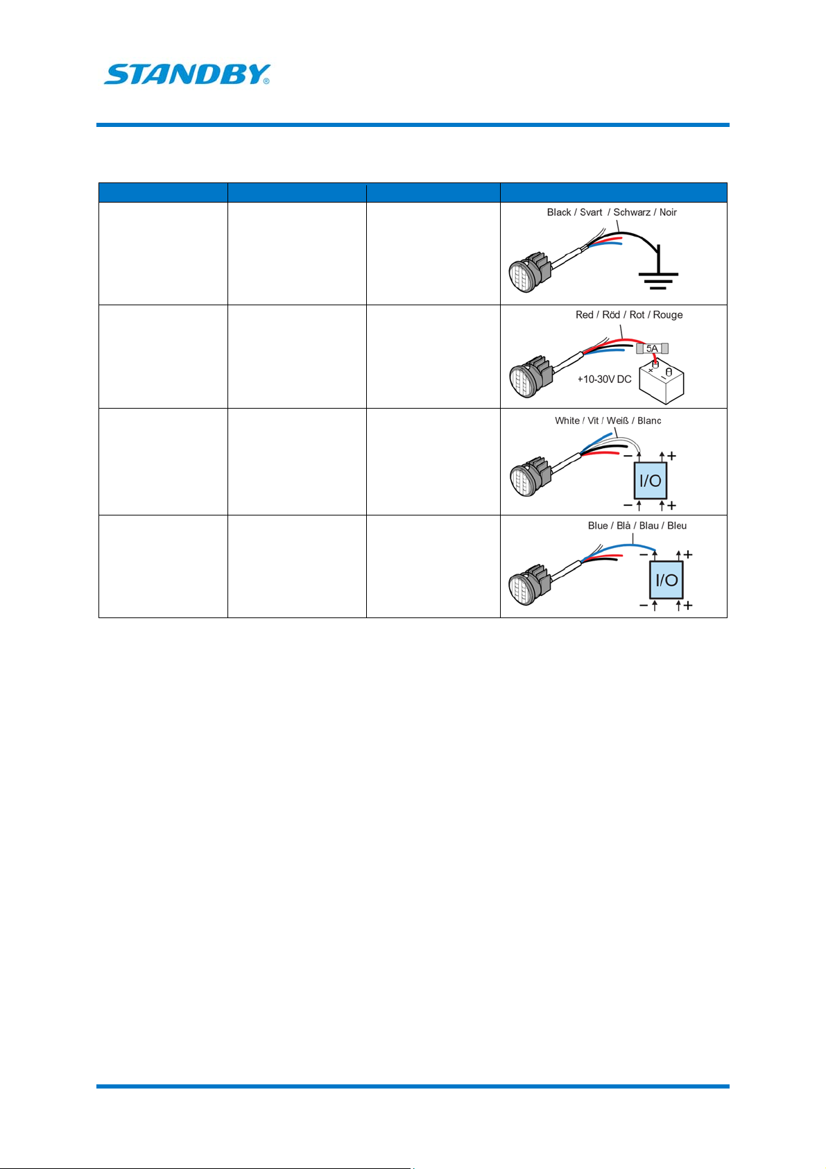
Connections
The function of each wire and how to connect the wires depend on the chosen flash pattern setting.
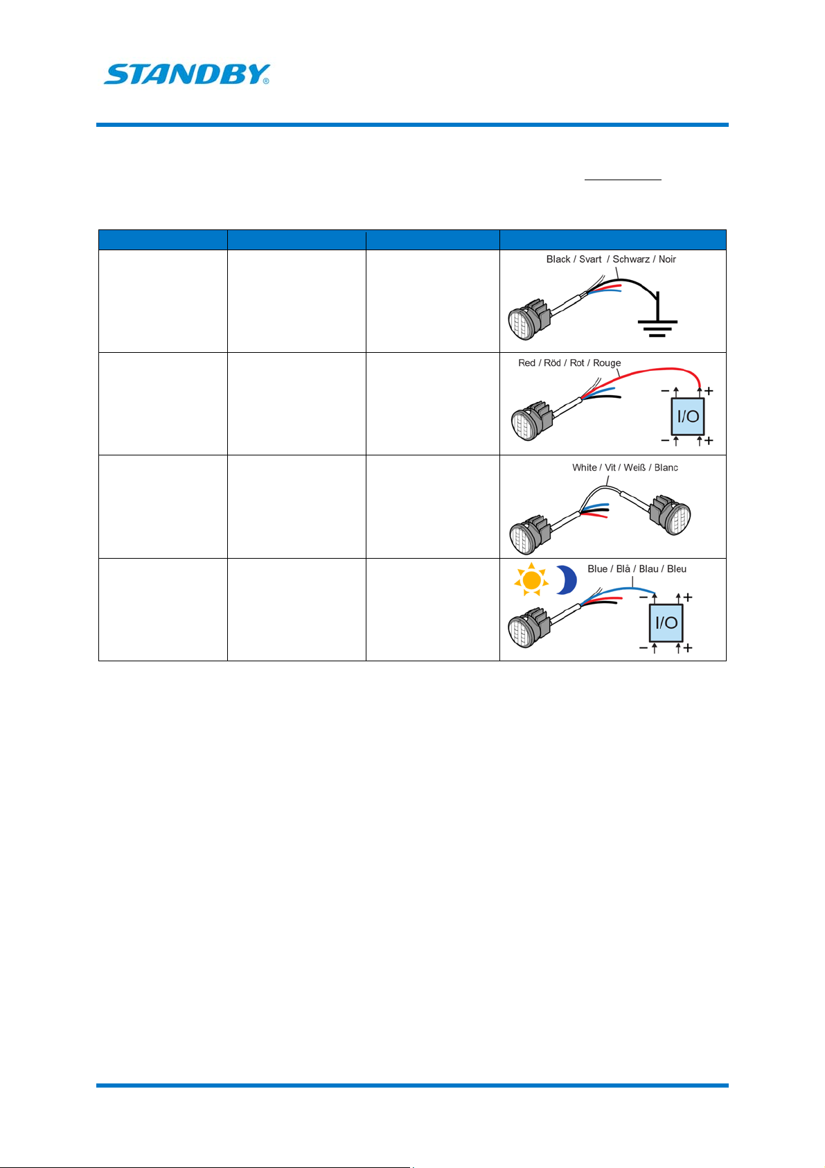
Table 1. Connections if flash pattern Double or Triple is selected.
Wire Functions Connect to
Black Power supply Good and suitable
ground
Red Power supply
Lamp on/off
10-30 V DC via a 5 A
fuse
Sourcing output (+) of
an I/O unit or via a
switch
White Synchronizing the
flashing of two or more
lamps
Sync cable of the other
lamp
Blue Day-and-night function Sinking output (-) of an
I/O unit or via a switch
to ground. When
activated, the lamp
dims down to night
level
L88 Amber – Manual
WAM488AmberA 9 Standby AB – standbygroup.se
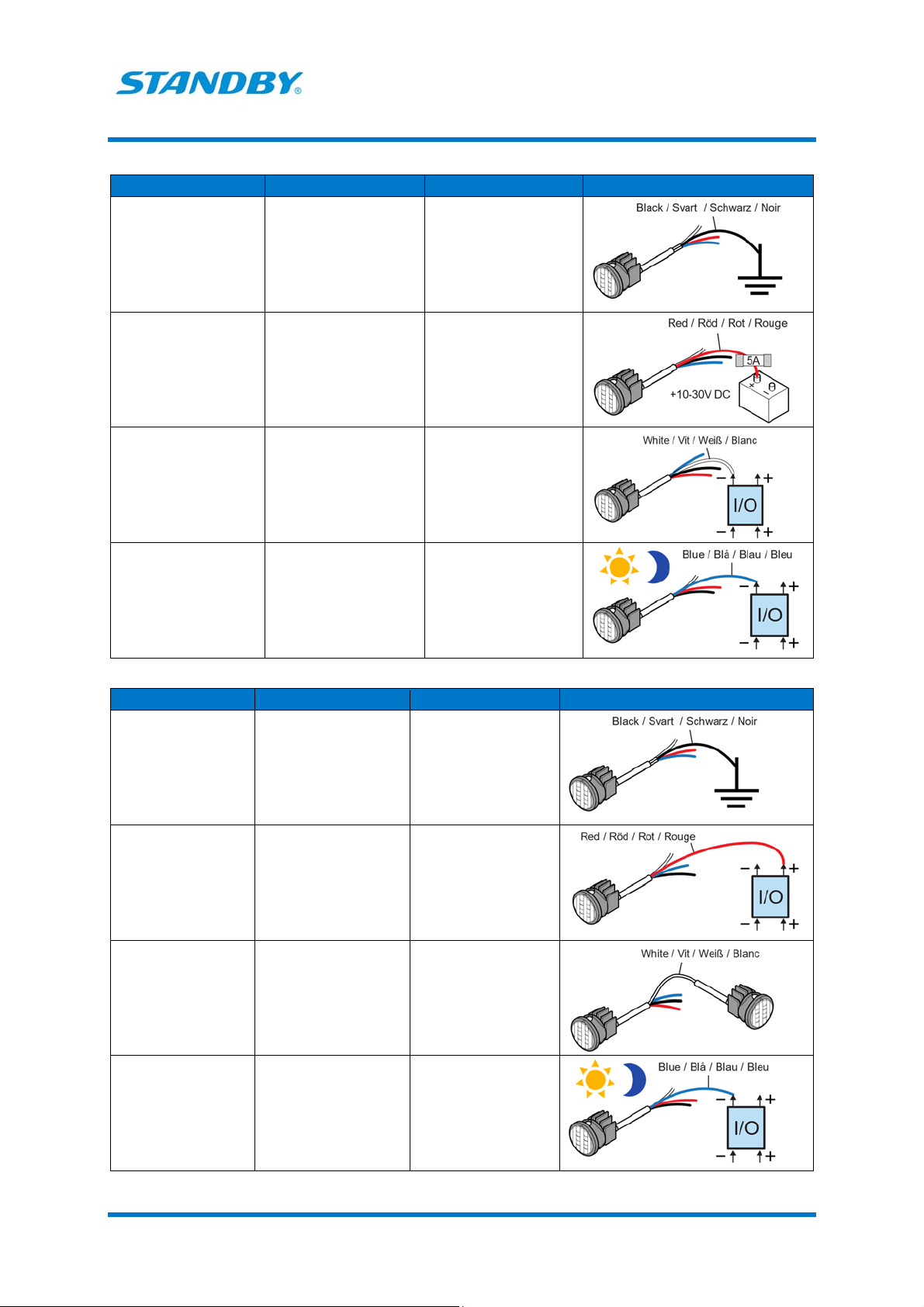
Table 2. Connections if flash pattern Steady burn 1 is selected.
Wire Functions Connect to
Black Power supply Good and suitable
ground
Red Power supply 10-30 V DC via a 5 A fuse
White Lamp on/off Sinking output (-) of an
I/O unit or external
flasher.
Blue Day-and-night function Sinking output (-) of an
I/O unit or via a switch to
ground. When activated,
the lamp dims down to
night level
Table 3. Connections if flash pattern Steady burn 2 is selected.
Wire Functions Connect to
Black Power supply Good and suitable
ground
Red Power supply
Lamp on/off
10-30 V DC via a 5 A
fuse
Sourcing output (+) of
an I/O unit or external
flasher
White Synchronizing the
flashing of two or more
lamps
Sync cable of the other
lamp
Blue Day-and-night function Sinking output (-) of an
I/O unit or via a switch
to ground. When
activated, the lamp
dims down to night
level
L88 Amber – Manual
WAM488AmberA 10 Standby AB – standbygroup.se
Table 4. Connections if flash pattern Indicator is selected.
Wire Functions Connect to
Black Power supply Good and suitable
ground
Red Power supply 10-30 V DC via a 5 A
fuse
White Indicator lamp 2 on/off Sinking output (-) of an
I/O unit or external
flasher. When activated,
the lamp goes on with
10% luminosity
Blue Indicator lamp 1 on/off Sourcing output (+) of
an I/O unit
L88 Amber – Manual
WAM488AmberA 11 Standby AB – standbygroup.se
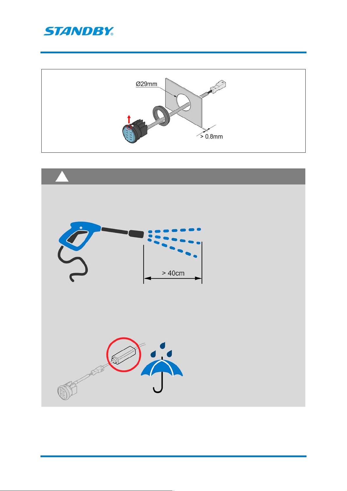
Installation
CAUTION
To prevent moisture from entering the lamp through the cable end, make sure that the cable
end is sealed or located in a dry part of the vehicle.
When using a pressure washer, keep a minimum distance of 40 cm.
Do not let grease, oil or any foreign substances come in contact with the Gore-Tex™
membrane on the lamp.
Do not damage the Gore-Tex™ membrane on the lamp.
The driver must be located in a weather protected area.
!
Other manuals for L88
2
Table of contents
Other Standby Automobile Accessories manuals

Standby
Standby L52 2C User manual

Standby
Standby LB200 User manual

Standby
Standby P1 PANEL User manual

Standby
Standby L88 User manual

Standby
Standby W3 User manual

Standby
Standby L56 2C User manual

Standby
Standby L54 User manual

Standby
Standby L54 User manual

Standby
Standby L52 User manual

Standby
Standby W3 User manual


