manuals.online logo
Brands
  1. Home
  2. •
  3. Brands
  4. •
  5. Standby
  6. •
  7. Automobile Accessories
  8. •
  9. Standby L52 2C User manual

Standby L52 2C User manual

L52 2C –Manual
WAM4522CB 1 Standby AB –standbygroup.se
L52 2C
Thank you for choosing a product from Standby.
Technical Data
Lens
Polycarbonate
Diodes
6+6 high power LED
Cable
2 m, basic version
Power
10-30 V DC
Ambient temperature
-40ºC to +85ºC
Power consumption
0.8 A peak at 13.8 V
0.4 A peak at 27.6 V
Size
113 x 28 x 9 mm
Approvals
Light: ECE R65 (E5)
EMC: ECE R10 (E5)
IP6K9K
Included
1 x L52 Lamp 2C
1 x gasket
1 x assembly kit
Synchronizing
12 V: Up to 12 lamps
24 V: Up to 8 lamps
Preset Settings
Part
number
Color 1
Color 2
Flash pattern
Sync mode
Input X2/X3
Color 1
Color 2
Color 1
Color 2
Color 1
Color 2
45257031
Blue
Amber
Double
Double
Simultaneous
Alternate
Pull down
Pull down
45257032
Blue
Red
Steady
45257033
Blue
White
Steady
45257034
Blue
Green
Double
45267031
Red
White
Double
45287031
Amber
White
Steady
45287032
Green
Amber
Double
45287034
Amber
Red
Steady
To change the flash pattern setting, see Flash Pattern. To change the sync mode setting, see Sync Mode. To change the input
X2/X3 setting, see Input X2/X3.
L52 2C –Manual
WAM4522CB 2 Standby AB –standbygroup.se
Flash Pattern
Introduction
The flash pattern setting controls the flash pattern. There are seven available combinations of flash
patterns, see table.
•Double, Triple and Steady burn are built-in flash patterns and no control system is
needed.
•With Steady burn 1, Steady burn 2 and Steady burn 3 an external flasher or control
system is used to control the flash pattern.
The preset setting of flash pattern depends on the version of the lamp, see Preset Settings.
When in configuration mode, the number of blank flashes (lamp off) in the flash sequence show the
current flash pattern setting, see table.
Blank flashes per
flash sequence
Flash pattern
Flash control
Color 1
Color 2
1
Double
Double
Built-in
2
Triple
Triple
Built-in
3
Double
Steady burn
Built-in
4
Triple
Steady burn
Built-in
5
Steady burn 1
Steady burn 1
External
6
Steady burn 2
Steady burn 2
External
7
Double
Steady burn 3
Built-in/External
L52 2C –Manual
WAM4522CB 3 Standby AB –standbygroup.se
Setting the Flash Pattern
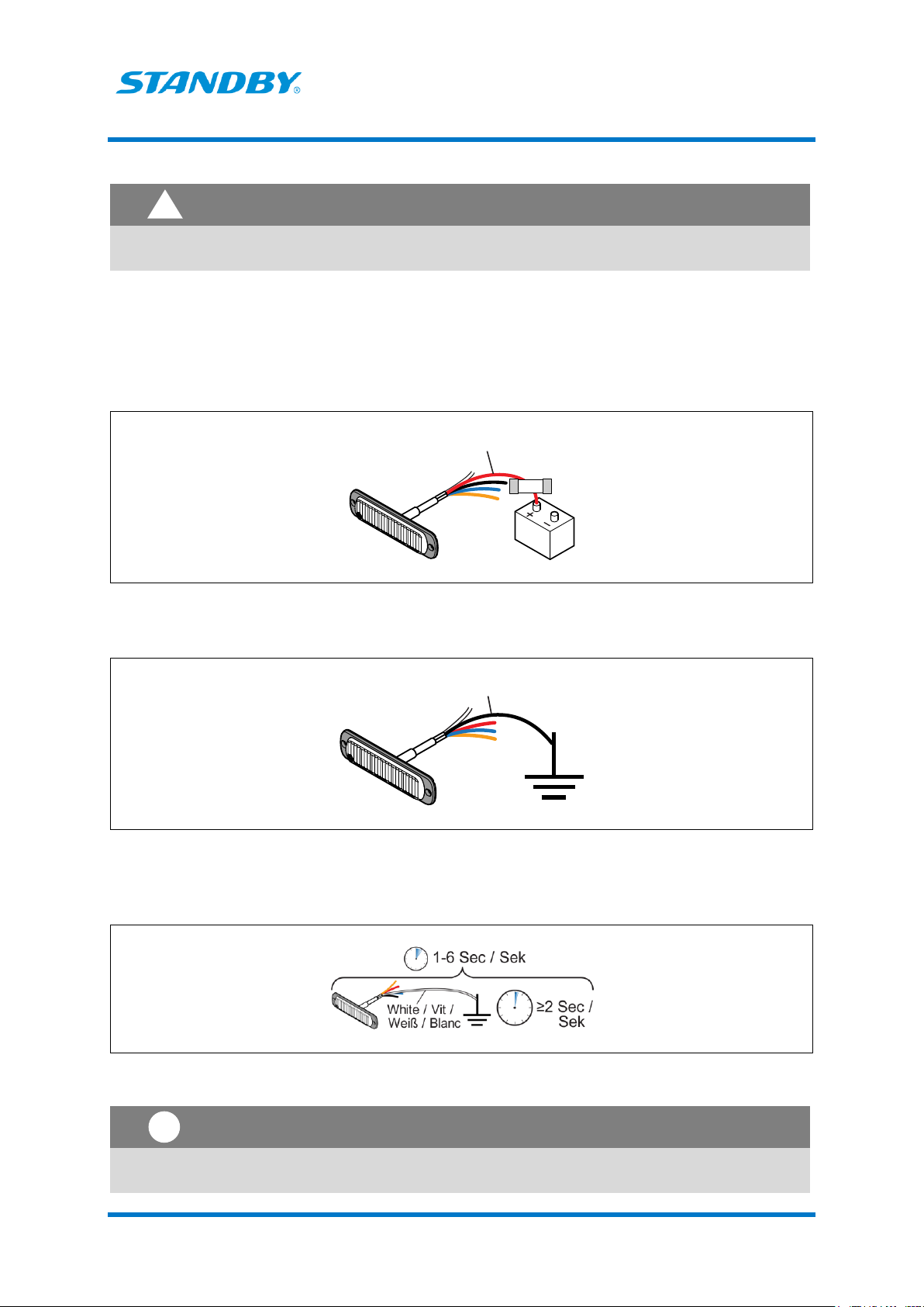
WARNING
Risk of eye damage. Do not look into the beam at close range.
1. If already in configuration mode, go to step 6.
2. If the lamp is connected to the power supply, disconnect it.
3. Connect the red wire to 10-30 V DC via a 5 A fuse.
4. Connect the black wire to ground.
5. Within 1 to 6 sec: temporarily connect the white wire to ground and let it stay connected for at
least 2 sec.
The lamp enters configuration mode and a flash sequence indicating the current settings starts.
Note
If this step is performed incorrectly, you must restart from step 2.




!
!
L52 2C –Manual
WAM4522CB 4 Standby AB –standbygroup.se
6. Temporarily connect the white wire to ground to enter configuration mode for flash pattern.
7. Count the number of blank flashes (lamp off) per flash sequence to find out the current flash
pattern setting.
8. Temporarily connect the white wire to ground to change to the next version of flash pattern. Each
time the white wire is temporarily connected to ground the next version of flash pattern is selected.
9. To change the sync mode setting, see Sync Mode. To change the input X2/X3 setting, see Input
X2/X3. To reset to factory settings, see Factory Reset.
10. Disconnect the power supply to save the selected settings and exit configuration mode.


L52 2C –Manual
WAM4522CB 5 Standby AB –standbygroup.se
Sync Mode
Introduction
The sync mode setting controls how the flashing of two or more lamps is synchronized. There are four
available combinations of sync mode, see table.
•Simultaneous means that the lamps are in sync, that is they come on and go off at the
same time.
•Alternate means that the lamps are out of sync.
The preset setting of sync mode is Simultaneous for color 1 and Alternate for color 2.
When in configuration mode, the number of bright flashes of color 1 per flash sequence show the
current sync mode setting, see table.
Bright flashes (color 1)
per flash sequence
Sync mode
Color 1
Color 2
1
Simultaneous
Alternate
2
Alternate
Simultaneous
3
Alternate
Alternate
4
Simultaneous
Simultaneous
L52 2C –Manual
WAM4522CB 6 Standby AB –standbygroup.se
Setting the Sync Mode
WARNING
Risk of eye damage. Do not look into the beam at close range.
1. If already in configuration mode, go to step 6.
2. If the lamp is connected to the power supply, disconnect it.
3. Connect the red wire to 10-30 V DC via a 5 A fuse.
4. Connect the black wire to ground.
5. Within 1 to 6 sec: temporarily connect the white wire to ground and let it stay connected for at
least 2 sec.
The lamp enters configuration mode and a flash sequence indicating the current settings starts.
Note
If this step is performed incorrectly, you must restart from step 2.




!
!
L52 2C –Manual
WAM4522CB 7 Standby AB –standbygroup.se
6. Temporarily connect the blue wire to ground to enter configuration mode for sync mode.
7. Count the number of bright flashes of color 1 per flash sequence to find out the current sync mode
setting.
8. Temporarily connect the blue wire to ground again to change to the next version of sync
mode. Each time the blue wire is temporarily connected to ground the next version of sync mode is
selected.
9. To change the flash pattern setting, see Flash Pattern. To change the input X2/X3 setting,
see Input X2/X3. To reset to factory settings, see Factory Reset.
10. Disconnect the power supply to save the selected settings and exit configuration mode.


L52 2C –Manual
WAM4522CB 8 Standby AB –standbygroup.se
Input X2/X3
Introduction
The input X2/X3 controls how the colors of the lamp are activated. There are four available
combinations of input X2/X3, see table.
•Pull down means that the color is activated by a sourcing signal (+).
•Pull up means that the color is activated by a sinking signal (-).
The preset setting of input X2/X3 mode is Pull Down for both color 1 and color 2.
When in configuration mode, the number of bright flashes of color 2 in the flash sequence show the
current input X2/X3 setting, see table.
Bright flashes (color 2) per
flash sequence
Input X2/X3
Color 1
Color 2
1
Pull down
Pull down
2
Pull up
Pull up
3
Pull down
Pull up
4
Pull up
Pull down
Setting the Input X2/X3
WARNING
Risk of eye damage. Do not look into the beam at close range.
1. If already in configuration mode, go to step 6.
2. If the lamp is connected to the power supply, disconnect it.
3. Connect the red wire to 10-30 V DC via a 5 A fuse.
4. Connect the black wire to ground.




!
L52 2C –Manual
WAM4522CB 9 Standby AB –standbygroup.se
5. Within 1 to 6 sec: temporarily connect the white wire to ground and let it stay connected for at
least 2 sec.
The lamp enters configuration mode and a flash sequence indicating the current settings starts.
Note
If this step is performed incorrectly, you must restart from step 2.
6. Temporarily connect the orange wire to ground to enter configuration mode for input X2/X3.
7. Count the number of bright flashes of color 2 to find out the current input X2/X3 setting.
8. Temporarily connect the orange wire to ground again to change to the next version of input X2/X3.
Each time the orange wire is connected to ground the next version of input X2/X3 is selected.
9. To change the flash pattern setting, see Flash Pattern. To change the sync mode setting, see Sync
Mode. To reset to factory settings, see Factory Reset.
10. Disconnect the power supply to save the selected settings and exit configuration mode.
 
 
!
L52 2C –Manual
WAM4522CB 10 Standby AB –standbygroup.se
Factory Reset
Introduction
The settings can be changed back to the factory settings.
The factory settings are the following(color 1/color 2):
•Flash pattern - Double/Double
•Sync mode - Simultaneous/Alternate
•Input X2/X3 - Pull down/pull down
Reset to Factory Settings
WARNING
Risk of eye damage. Do not look into the beam at close range.
Note
All current settings, that is flash pattern setting, sync mode setting and Input X2/X3, are reset
to the default settings.
1. If already in configuration mode, go to step 6.
2. If the lamp is connected to the power supply, disconnect it.
3. Connect the red wire to 10-30 V DC via a 5 A fuse.
4. Connect the black wire to ground.




!
!
L52 2C –Manual
WAM4522CB 11 Standby AB –standbygroup.se
5. Within 1 to 6 sec: temporarily connect the white wire to ground and let it stay connected for at
least 2 sec.
The lamp enters configuration mode and a flash sequence indicating the current settings starts.
Note
If this step is performed incorrectly, you must restart from step 2.
6. Connect the BLUE and the WHITE wire to ground and let them stay connected for at least 2
seconds.
7. The reset is confirmed with a bright steady light for 2-3 seconds.
!
L52 2C –Manual
WAM4522CB 12 Standby AB –standbygroup.se
Connections
The function of each wire and how to connect the wires depend on which version of flash pattern and
input X2/X3 that is selected, see tables below.
For more information about flash pattern and input X2/X3, see Flash Pattern and Input X2/X3.
Table 1. Connections when flash pattern Double/Double, Double/Triple, Double/Steady
burn or Triple/Steady burn is selected.
Wire
Functions
Connect to
Black
Power supply
Good and suitable ground
Red
Power supply
10-30 V DC via a 5 A fuse
Blue
Activates the flashing of
color 1
Sourcing output (+) of an
I/O unit*
Orange
Activates the flashing of
color 2
Sourcing output (+) of an
I/O unit**
White
Synchronizes the flashing
of two or more lamps
Sync cable of the other
lamps










L52 2C –Manual
WAM4522CB 13 Standby AB –standbygroup.se
Table 2. Connections when flash pattern Steady burn 1/Steady burn 1 is selected.
Wire
Functions
Connect to
Black
Power supply
Good and suitable ground
Red
Power supply
10-30 V DC via a 5 A fuse
Blue
Activating Steady burn for
color 1
Sourcing output (+) of an
I/O unit*
Orange
Activating Steady burn for
color 2
Sourcing output (+) of an
I/O unit**
White
Change color 1 from
Steady burn to Double
Change color 2 from
Steady burn to Double
Ground when color 1 is
active
Ground when color 2 is
active









L52 2C –Manual
WAM4522CB 14 Standby AB –standbygroup.se
Table 3. Connections when flash pattern Steady burn 2/Steady burn 2 is selected.
Wire
Functions
Connect to
Black
Power supply
Good and suitable ground
Red
Power supply
10-30 V DC via a 5 A fuse
Blue
Activating Steady burn for
color 1
Sourcing output (+) of an
I/O unit*
Orange
Activating Steady burn for
color 2
Sourcing output (+) of an
I/O unit**
White
Change color 1 from
Steady burn to Triple
Change color 2 from
Steady burn to Triple
Ground when color 1 is
active
Ground when color 2 is
active









L52 2C –Manual
WAM4522CB 15 Standby AB –standbygroup.se
Table 4. Connections when flash pattern Double/Steady burn 3 is selected.
Wire
Functions
Connect to
Black
Power supply
Good and suitable
ground
Red
Power supply
Activating the flashing of
color 1
10-30 V DC via a 5 A
fuse
Sourcing (+) output of
an I/O unit
Blue
Activating Steady burn
for color 2
Direction-indicator
control system or
sourcing output (+) of
an I/O unit
Orange
Change from color 1 to
color 2
Sourcing output (+) of
an I/O unit
White
Synchronizing the
flashing of two or more
lamps
Sync cable of the other
lamps
* If input X2/X3 for color 1 is Pull down. If not, connect the wire to a sinking output (-) of an I/O unit.
** If input X2/X3 for color 2 is Pull down. If not, connect the wire to a sinking output (-) of an I/O unit.








L52 2C –Manual
WAM4522CB 16 Standby AB –standbygroup.se
Installation
CAUTION
The lamp must be mounted on a flat surface.
To prevent moisture from entering the lamp through the cable end, make sure that the cable
end is sealed or located in a dry part of the vehicle.
When using a pressure washer, keep a minimum distance of 40 cm.



!

This manual suits for next models

8

Other Standby Automobile Accessories manuals

Standby W3 User manual

Standby

Standby W3 User manual

Standby W3 User manual

Standby

Standby W3 User manual

Standby L88 User manual

Standby

Standby L88 User manual

Standby Vega User manual

Standby

Standby Vega User manual

Standby P4 User manual

Standby

Standby P4 User manual

Standby L88 User manual

Standby

Standby L88 User manual

Standby L54 User manual

Standby

Standby L54 User manual

Standby L56 2C User manual

Standby

Standby L56 2C User manual

Standby Vega User manual

Standby

Standby Vega User manual

Standby L54 User manual

Standby

Standby L54 User manual

Standby L52 User manual

Standby

Standby L52 User manual

Standby LB200 User manual

Standby

Standby LB200 User manual

Standby L52 User manual

Standby

Standby L52 User manual

Standby P1 PANEL User manual

Standby

Standby P1 PANEL User manual

Popular Automobile Accessories manuals by other brands

Axxess AXDSPL-VW1 installation instructions

Axxess

Axxess AXDSPL-VW1 installation instructions

KFI OPEN TRAIL instruction manual

KFI

KFI OPEN TRAIL instruction manual

ECS Electronics KI-132-DX Fitting instructions electric wiring

ECS Electronics

ECS Electronics KI-132-DX Fitting instructions electric wiring

Metra Electronics 70-7003 installation guide

Metra Electronics

Metra Electronics 70-7003 installation guide

iDataLink Maestro RR install guide

iDataLink

iDataLink Maestro RR install guide

Safe Fleet Prime Design VRR FT31B Assembly instructions

Safe Fleet

Safe Fleet Prime Design VRR FT31B Assembly instructions

UMBRA RIMORCHI 31080/C Fitting instructions

UMBRA RIMORCHI

UMBRA RIMORCHI 31080/C Fitting instructions

Prorack K334 Fitting instructions

Prorack

Prorack K334 Fitting instructions

JSPORT JSRLP024 installation instructions

JSPORT

JSPORT JSRLP024 installation instructions

iPark IPTSF407 manual

iPark

iPark IPTSF407 manual

CrimeStopper CS-840RKE installation guide

CrimeStopper

CrimeStopper CS-840RKE installation guide

CEMO DT-Mobil Easy 200 L Original operating instructions

CEMO

CEMO DT-Mobil Easy 200 L Original operating instructions

Skiguard Sport Install instructions

Skiguard

Skiguard Sport Install instructions

Dometic COOLAIR RT780 operating manual

Dometic

Dometic COOLAIR RT780 operating manual

curt 16993 installation manual

curt

curt 16993 installation manual

Luverne 431411 Installation instructions and parts list

Luverne

Luverne 431411 Installation instructions and parts list

Alfa Network Blue&me Installation

Alfa Network

Alfa Network Blue&me Installation

Gator ARV43M instruction manual

Gator

Gator ARV43M instruction manual

manuals.online logo
manuals.online logoBrands
  • About & Mission
  • Contact us
  • Privacy Policy
  • Terms and Conditions

Copyright 2025 Manuals.Online. All Rights Reserved.