Part Number: 76004-16100
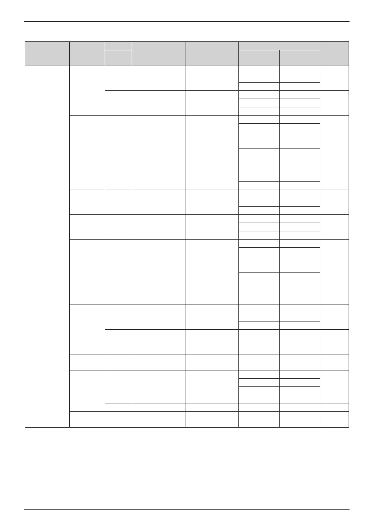
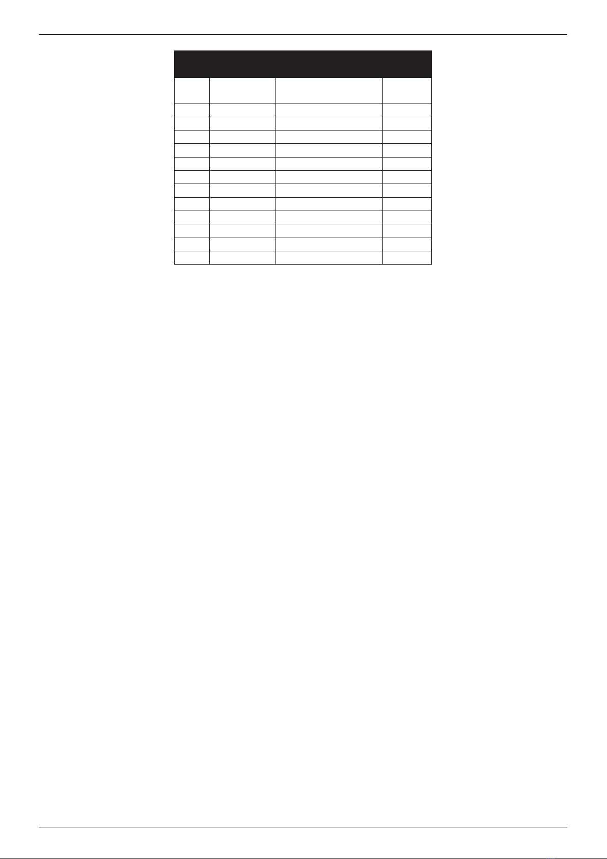
Item Part Number Description Qty
1 - Nose Pieces - Supplied
Separately
-
2 76003-16001 Nose Casing 1
3 07003-00067 O Ring 1
4 76003-16203 Jaw Guide 1
5 71230-16101 Jaws (3 pcs) 1 Set
6 07498-04502 Jaw Spreader 1
7 07498-03003 Buer 1
8 07500-00418 Jaw Pusher Spring 1
9 76003-16002 Pulling Head 1
10 76003-15004 Jaw Guide Lock 1
11 DPN901-020 Spring 1
12 76003-15003 Pulling Head Adapter 1
13 07003-00277 O Ring 1
FITTING INSTRUCTIONS
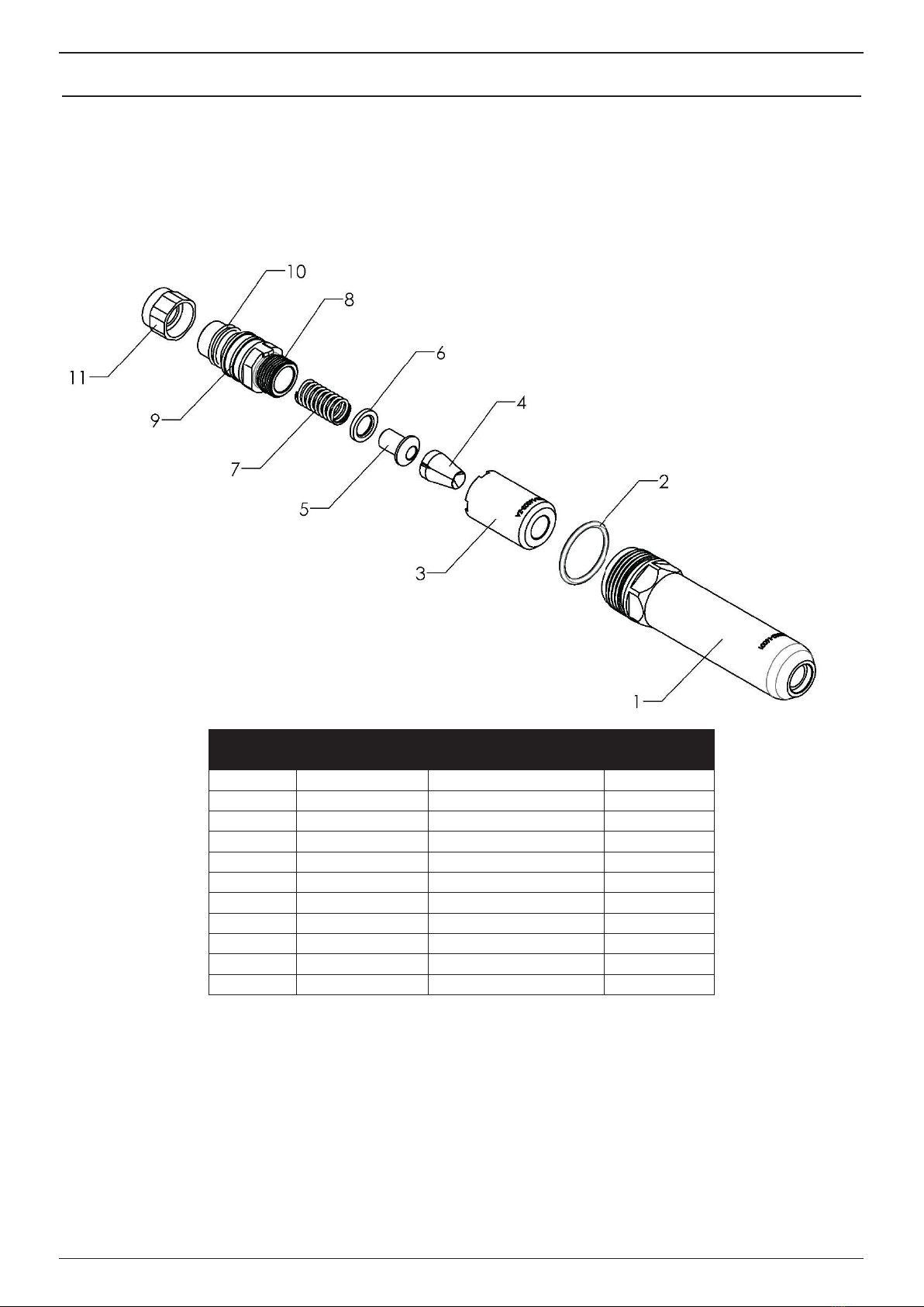
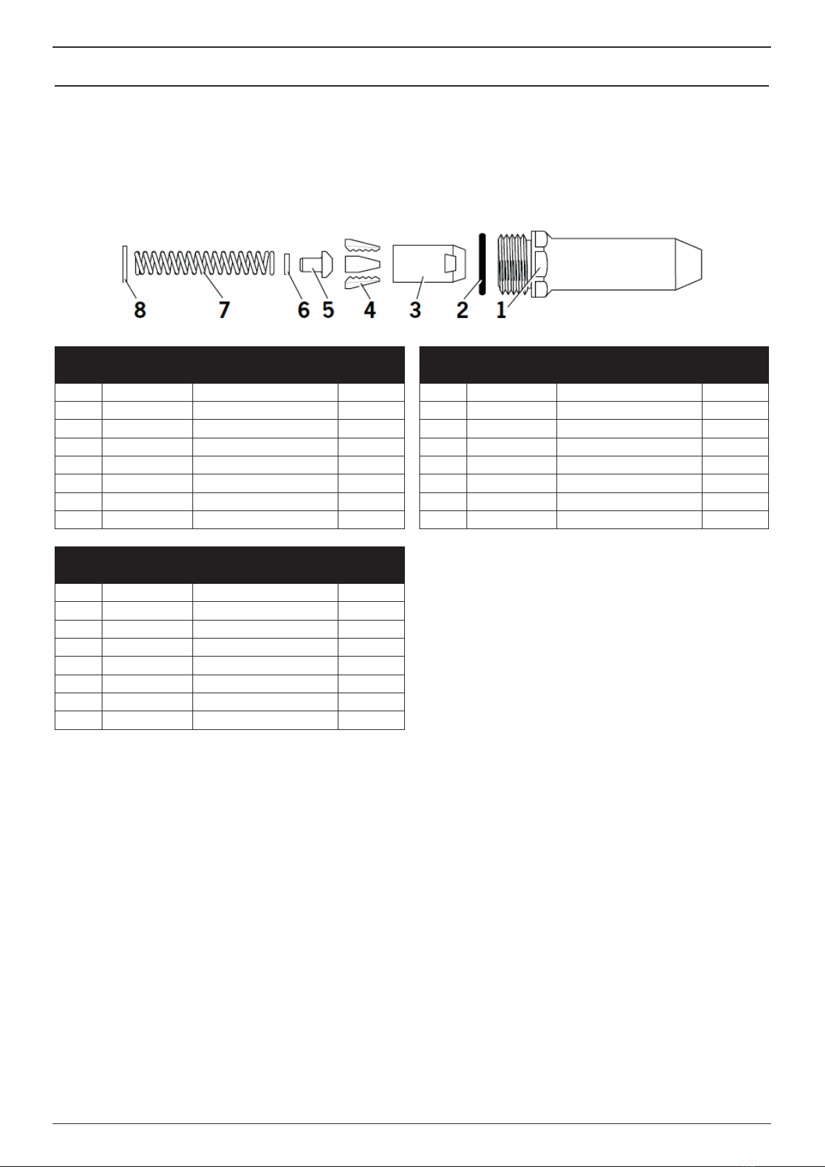
Item numbers in bold refer to nose assembly components in the tables and illustration above.
• The air supply must be disconnected.
• If necessary, remove the complete nose assembly 76003-15000 as described in the ProSet®XT3 and ProSet®XT4
instruction manual.
• Lightly coat jaws (5) with moly lithium grease.
• Drop Jaws (5) into the jaw guide (4).
• Insert the jaw pusher spring (8), jaw pusher or jaw spreader (6) and O ring or buer (7) into the pulling head (9).
• Pull back the jaw guide lock (10) and screw the jaw guide (4) fully on to the pulling head (9).
• Release the jaw guide lock (10) and then partially unscrew the jaw guide (4) until the jaw guide lock (10) tooth clicks
into the next slot on the jaw guide (4).
• Attach the pulling head assembly, Jaws Guide, Jaws, Jaw Pusher, Buer and Spring (4, 5, 6, 7, 8, 9, 10, 11, 12 & 13) to
the tool piston and then tighten the locknut (71210-02103) against it using spanners.
• Place nose casing (2) over the jaw guide (4) and tighten fully onto the tool.
• Nose tips (1) should be installed in the Nose Casing (2) and tightened to a torque of 7.0 – 7.5 Nm.
• If required, apply Loctite 932 on the Nose Tip (1) thread to prevent the part from coming loose in use.
SERVICING INSTRUCTIONS
• Nose assemblies need to be serviced at weekly intervals or every 5,000 cycles. Hold some stock of all internal
components of the nose assembly and nose pieces, they need regular replacement.
• The air supply must be disconnected.
• Remove the nose casing (2), including the nose piece (1), and O ring (3) from the tool.
• Pull back the jaw guide lock (10) against the spring (11) and then remove the jaw guide (4).
• Remove the jaws (5) from the jaw guide (4).
• Remove jaw pusher or jaw spreader (6), O ring or buer (7), and Jaw pusher spring (8), from the pulling head (9).
• Remove the pulling head assembly (9,10, 11, 12 & 13) from the tool piston using spanners
• Inspect all components. Any worn or damaged parts must be replaced by a new part.
• Particularly check wear on the Jaws (5).
• Clean all parts and apply moly lithium Grease (07992-00020) to jaws (5) and taper bore of jaw guide (4).
• Assemble according to tting instructions above.
9
ORIGINAL INSTRUCTION ENGLISH