Star Lake ROC300-TA45 User manual

F40-U
F40-U
F40-U
3U GPGPU short Depth Edge
Computing Server
User Manual
Intel® Xeon Silver Ice Lake 4310 12 Cores 2.1/3.3 GHz, 120W, 18MB cache
Dual Nvidia MXM RTX A4500 5888 CUDA cores PCIe Gen 4.0 x16
Two Ethernet LAN ports (LAN1, LAN2) and a dedicated IPMI LAN
4x NVMe M.2 (Gen4 x4)
Equipped with latest tool less design, storage, HDD trays, system fa
ns and PCIe riser brackets for easy upgrades and maintenance.
Size: 450.0 x 450.0 x 131.0 mm.
4x 80mm Fan, 11000RPM
Redundant 2U 1600W 1+1 CRPS
ROC300-TA45

Contents/目錄
1Chapter1 : General Information......................................................................................................7
1.1 Introduction...............................................................................................................................7
1.2 Specifications.............................................................................................................................8
1.3 Power Supply Options… .........................................................................................................9
1.4 Environmental Specifications... ...........................................................................................10
1.4.1 Table1.2 list ............................................................................................................................10
1.4.2 Dimension Diagram................................................................................................................10
1.4.3 Feature Overview ...............................................................................................................11
1.5 Removing the Top Cover......................................................................................................11
1.6 Installing the GPU Card.........................................................................................................12
1.6.1 Remove the PCIe slot cover....................................................................................................12
1.6.2 Plug the MXM carrier card with MXM GPU card into the PCIe slot1 (then 7 for 2nd MXM card) 12
1.6.3 Plug GPU power into the MXM carrier board........................................................................12
1.7 Installing Disk Drives..............................................................................................................13
1.7.1 Installing SSD in the Mobile SSD tray .....................................................................................13
1.7.2 Installing the SSD....................................................................................................................13
1.8 PSU Installation and Removal..............................................................................................14
1.8.1 CRPS module installation .......................................................................................................14
1.8.2 CRPS module removal ............................................................................................................14
1.9 Slide Rail or Pallet... ................................................................................................................14
2Chapter2 : Operation.. ....................................................................................................................16
2.1 The Front Panel... ....................................................................................................................16
2.1.1 Switch, Buttons and I/O Interfaces. .......................................................................................16
2.1.2 LED indicators for System Status............................................................................................16
2.1.3 LED Indicators for SSD Power & Status ..................................................................................16
2.2 The Rear Panel.........................................................................................................................16
2.2.1 Plug the AC power with standard IEC power cable................................................................17
2.2.2 Plug the cable into the I/O jack by the Device .......................................................................17
2.2.3 Broke the cover to install function card into PCIe slot...........................................................17
2.3 Replacing the system Cooling Fan... ..................................................................................17
3Chapter 3 : Motherboard Overview.............................................................................................18
3.1 Motherboard Image….................................................................................................................18
3.2 Motherboard Layout…................................................................................................................19
3.3 System Diagram….......................................................................................................................21
3.4 Memory Support and Installation…............................................................................................21
3.4.1 DIMM Installation...................................................................................................................22
3.4.2 DIMM Removal.......................................................................................................................23
3.4.3 Rear I/O Ports.........................................................................................................................23

3.4.4 Universal Serial Bus (USB) Ports and Headers........................................................................24
3.5 Troubleshooting Procedures…....................................................................................................24
3.5.1 Before Power On....................................................................................................................24
3.5.2 No Power................................................................................................................................25
3.5.3 No Video.................................................................................................................................25
3.5.4 System Boot Failure................................................................................................................25
3.5.5 Memory Errors .......................................................................................................................25
3.5.6 Losing the System's Setup Configuration...............................................................................26
3.6 Battery Removal and Installation….............................................................................................26
3.6.1 Battery Removal.....................................................................................................................26
3.6.2 Proper Battery Disposal..........................................................................................................26
3.6.3 Battery Installation.................................................................................................................26
4Chapter 4 : UEFI BIOS......................................................................................................................27
4.1 Introduction.............................................................................................................................27
4.2 Main Setup...............................................................................................................................27
4.2.1 Advanced Setup Configurations.........................................................................................29
4.2.2 Boot Feature...........................................................................................................................29
4.2.3 CPU Configuration..................................................................................................................30
4.2.4 CPU1 Core Disable Bitmap .....................................................................................................31
4.2.5 Advanced Power Management Configuration.......................................................................33
4.2.5.1 CPU P State Control................................................................................................................34
4.2.5.2 Hardware PM State Control ...................................................................................................34
4.2.5.3 CPU C State Control................................................................................................................35
4.2.5.4 Package C State Control .........................................................................................................35
4.2.5.5 CPU T State Control................................................................................................................35
4.2.6 Chipset Configuration.............................................................................................................35
4.2.6.1 North Bridge...........................................................................................................................35
4.2.6.2 Uncore Configuration.............................................................................................................35
4.2.6.3 Memory Configuration...........................................................................................................37
4.2.6.4 Memory Topology..................................................................................................................37
4.2.6.5 Memory RAS Reliability_Availability_Serviceability Configuration........................................37
4.2.7 I/O Configuration....................................................................................................................38
4.2.7.1 CPU1 Configuration................................................................................................................38
4.2.7.2 IOAT Configuration.................................................................................................................38
4.2.7.3 Intel® VT for Directed I/O(VT-d).............................................................................................39
4.2.7.4 Intel®VMD (Volume Management Device) Technology.........................................................39
4.2.7.5 Intel® VMD for Volume Management Device on CPU1 .........................................................39
4.2.8 South Bridge...........................................................................................................................40
4.2.9 Server ME Configuration........................................................................................................40
4.2.10 PCH SATA Configuration.........................................................................................................41

4.2.11 Network Configuration...........................................................................................................42
4.2.11.1MAC: (MAC address)-IPv4 Netwrok Configuration................................................................42
4.2.11.2MAC: (MAC address)-IPv6 Netwrok Configuration................................................................43
4.2.11.3Enter Configuration Menu .....................................................................................................43
4.2.11.4Advanced Configuration.........................................................................................................43
4.2.12 KMIP Server Configuration.....................................................................................................43
4.2.12.1CA Certificate..........................................................................................................................44
4.2.12.2Client Certificate.....................................................................................................................44
4.2.12.3Client Private Key ...................................................................................................................44
4.2.13 PCIe/PCI/PnP Configuration...................................................................................................44
4.2.14 Super IO Configuration...........................................................................................................45
4.2.14.1Serial Port 1 Configuration.....................................................................................................46
4.2.14.2Serial Port 2 Configuration.....................................................................................................46
4.2.14.3Serial Port Console Redirection..............................................................................................46
4.2.14.3.1 Console Redirection Settings (Available when the Console Redirection is set to Enabled) 46
4.2.14.3.2 Console Redirection Settings (Available when the Console Redirection is set to Enabled) 48
4.2.14.3.3 Console Rediredtion Settings (Available when the Console Redirection EMS is set to Enable)49
4.2.15 ACPI Settings ..........................................................................................................................50
4.2.16 Trusted Computing (Available when a TPM device is installed and detected by the BIOS)..50
4.2.17 HTTP Boot Configuration........................................................................................................52
4.2.18 iSCSI Configuration.................................................................................................................52
4.2.18.1Attempt Priority .....................................................................................................................52
4.2.18.2Host iSCSI Configuration.........................................................................................................52
4.2.18.3Add an Attempt......................................................................................................................53
4.2.18.4Delete Attempts.....................................................................................................................53
4.2.18.5Change Attempt Order...........................................................................................................53
4.2.19 Intel® i210 Gigabit Netwrok Connection –(MAC address) ....................................................53
4.2.19.1Firmware Image Properties....................................................................................................53
4.2.19.2NIC Configuration...................................................................................................................53
4.2.20 TLS Authenticate Configuration .............................................................................................54
4.2.20.1Server CA Configuration / Client Certification Configuration ................................................54
4.2.20.2Enroll Certification..................................................................................................................54
4.2.20.3Enroll Certification Using File.................................................................................................54
4.2.20.4Commit Changes and Exit.......................................................................................................54
4.2.20.5Discard Changes and Exit .......................................................................................................54
4.2.20.6Delete Certification ................................................................................................................54
4.2.21 Driver Health ..........................................................................................................................54
4.3 Event Logs................................................................................................................................54
4.3.1 Change SMBIOS Event Log Settings .......................................................................................55
4.3.2 View SEMBIOS Event Log .......................................................................................................55

4.4 IPMI............................................................................................................................................55
4.4.1 System Event Log ...................................................................................................................56
4.4.2 BMC Network Configuration..................................................................................................57
4.5 Security .....................................................................................................................................58
4.5.1 SMCI Securuty Erase Configuration........................................................................................59
4.5.2 Secure Boot ............................................................................................................................60
4.5.2.1 Enter Audit Mode...................................................................................................................60
4.5.2.2 Enter Deployed Mode / Exit Deployed Mode ........................................................................60
4.5.3 Key Management (Available when Secure Boot Mode is set to Custom)..............................60
4.5.3.1 Restore Factory Keys..............................................................................................................61
4.5.3.2 Reset to Setup Mode..............................................................................................................61
4.5.3.3 Export Secure Boot variable...................................................................................................61
4.5.3.4 Enroll EFI Image......................................................................................................................61
4.5.3.5 Remove ‘UEFI CA’ from DB.....................................................................................................61
4.5.3.6 Restore DB defaults................................................................................................................61
4.5.3.7 Platform Key(PK) ....................................................................................................................61
4.5.3.8 Key Exchange Keys .................................................................................................................61
4.5.3.9 Authorized Signatures............................................................................................................62
4.5.3.10 Forbidden Signatures .............................................................................................................62
4.5.3.11 Authorized TimeStamps.........................................................................................................62
4.5.3.12 OsRecovery Signature ............................................................................................................63
4.5.4 TCG Storage Device Security Configuration...........................................................................63
4.5.5 Storage Device........................................................................................................................63
4.5.6 Password Configuration .........................................................................................................63
4.5.7 Set Admin Passwrod...............................................................................................................64
4.5.8 Set User Passwrod..................................................................................................................64
4.6 Boot ...........................................................................................................................................64
4.6.1 Delete Boot Option ................................................................................................................66
4.6.2 UEFI Network Drive BBS Priorities..........................................................................................66
4.6.3 UEFI Application Boot Priorities .............................................................................................66
4.6.4 Add New Boot Option ............................................................................................................66
4.6.5 UEFI USB Key Drive BBS Priorities ..........................................................................................66
4.6.6 USB Key Drive BBS Priorities ..................................................................................................66
4.6.7 UEFI Hard Disk BBS Priorities..................................................................................................66
4.6.8 Hard Disk Drive BBS Prioritues ...............................................................................................66
4.7 Save & Exit ...............................................................................................................................66
5Appendix A BIOS POST Codes... ...................................................................................................68
5.1 BIOS POST Codes ...................................................................................................................68
6Appendix B SoftWare......................................................................................................................68

6.1 Microsoft Windows OS Installation....................................................................................68
6.2 Driver Installation ...................................................................................................................70
6.3 SuperDoctor® 5.....................................................................................................................71
6.4 IPMI............................................................................................................................................71
6.5 Logging into the BMC(Baseboard Management Controller).......................................72

7
1Chapter1 : General Information..
1.1 Introduction...
ROC300-TA45 is an efficient 3U rackmount workstation designed with the most advanced NVIDIA
Quadro RTX (A4500) professional GPU, specifically designed for the most demanding workflows of today.
Experience GPU acceleration performance through innovative computers and mobile devices that
combine real-time ray tracing, programmable shading technology, and artificial intelligence.
ROC300-TA45 adopts the latest industrial design, providing users with high-performance and
cutting-edge operating platforms. This machine supports EATX/ATX/MicroATX motherboards, with
efficient power switching and easy maintenance of fans. ROC300-TA45 provides 6 SAS/SATA HDD
Hot-Swap drive bays and 4 built-in M.2 SSD, providing a flexible solution for data storage. The
high-performance series can support up to 1600W power supply and has excellent heat dissipation
capacity to support up to two A4500 GPU cards and extra two acceleration cards. In addition, the system
fan can increase or decrease speed based on the temperature inside the chassis to effectively reduce
noise under low system loads. A wide range of standard computing peripherals can be integrated with
these chassis to accommodate robust applications in rugged environments, 24 hours a day, 7 days a
week.

8
1.2 Specifications...
Model Name
ROC300-TA45
Form Factor
EATX/ ATX/ Micro ATX
CPU
Intel Xeon Silver Ice Lake 4310 with Fansink
Chipset
C621A
Memory
DDR4 256GB (4x 64GB)
Display
1x VGA (AST2500)
GPU
2x NVIDIA MXM A4500 with Fansink
Storage
2x M.2 2TB NVMe
Front I/O
Indicators
1x Power Status; 2x LAN activity, 1x UID, 1x HDD Status; 1x System
Alarm
Front Control
1x Power On/Offf; 1x System Reset; 1x UID; 1x USB3.0
Drive Bay
6x SAS/SATA Hot-swap bay
Cooling Fan
4x 80x80 mm, 11000RPM, Hot-swap
Rear I/O
LAN
1x LAN1 : 1GbE ; 1x LAN2 : 10GbE
Net Work
1x IPMI (AST2500)
Display
1x VGA (AST2500)
Serial
4x USB3.2; 2x USB2.0; 1x Type C (USB3.2)
COM
1x COM
Audio
450 x 450 x 1
S/PDIF
1x out
PSU Form Factor
2U 1600W 1+1 CRPS
Expansion
PCIe Slot opening
2x MXM Carrier Card; 2x Opening slot for U55C
Dimension (D x W x H)
450.0 x 450.0 x 131.0 mm
9
1.3 Power Supply Options…
1.3.1 Features
1.3.1.1 A High Reliability PDB(power distribution board)
1.3.1.2 CRPS Module Compatible
1.3.1.3 2U Narrow Form Factor
1.3.1.4 Meet PMBus 1.2
1.3.1.5 Design for 5,000 Meter above Sea level
1.3.1.6 High Reliability
1.3.1.7 Low Ripple & Noise
1.3.1.8 Over Current Protection
1.3.1.9 Over Temperature Protection
1.3.1.10 Over Voltage Protection
1.3.2 Genernal Specification
GENERNAL SPECIFICATION
Dimension
210 x 76 x 83.8 mm(Lx W x H)
Hold-up Time at 100%
12V = 11ms
Operating Altitude
5,000 meters above Sea level
Environment
Working Temperature
0℃to 55℃
Storage Temperature
-40℃to +70℃
Working Humidity
5% to 90% RH non-condensing
Storage Humidity
5% to 95% RH non-condensing
MTBF
500,000 hours of continuous operation at 55℃, 100% output load.
1.3.3 Table 1.1:Power supply output rating
Output
power
Input
Voltage
Current Range
DC Outputs
+3.3V
+5V
+12V
-12V
+5VSB
1600W
100-240VAC
(1000W)
Max. Current
12A
24A
80.5A
0.3A
5A
Combined Power
972W
3.6W
25W
200-240VAC
(1600W)
Max. Current
12A
24A
130.3A
0.3A
5A
Combined Power
1572W
3.6W
25W
10
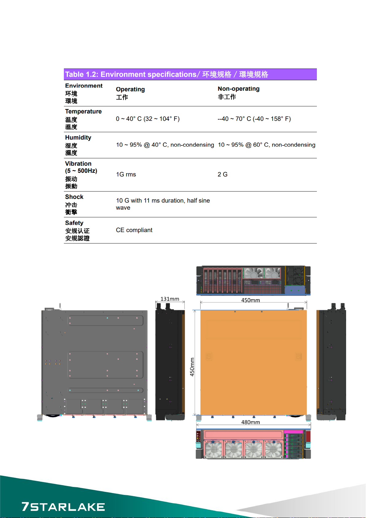
1.4 Environmental Specifications...
1.4.1 Table1.2 list
1.4.2 Dimension Diagram
11
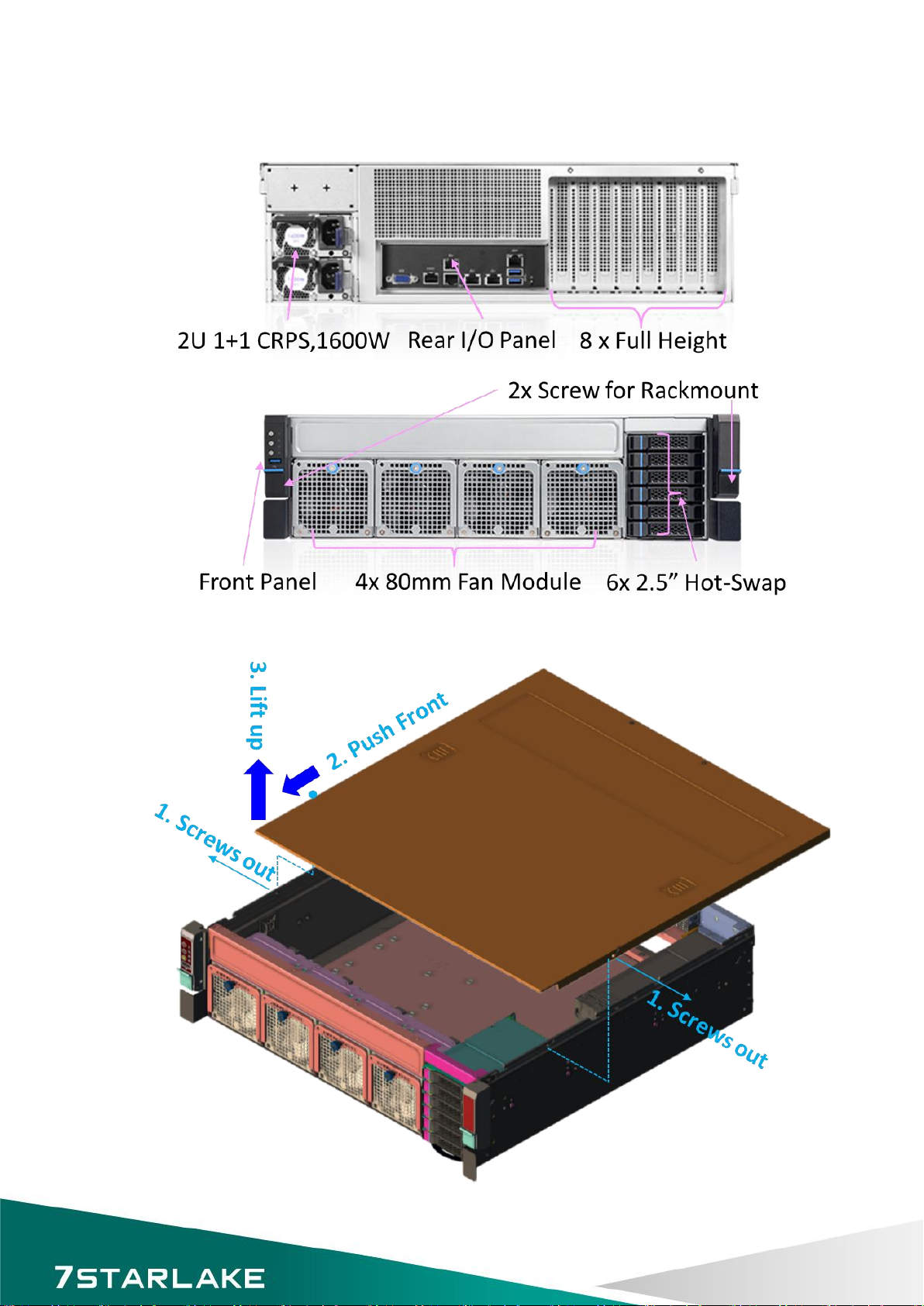
1.4.3 Feature Overview
1.5 Removing the Top Cover...
12
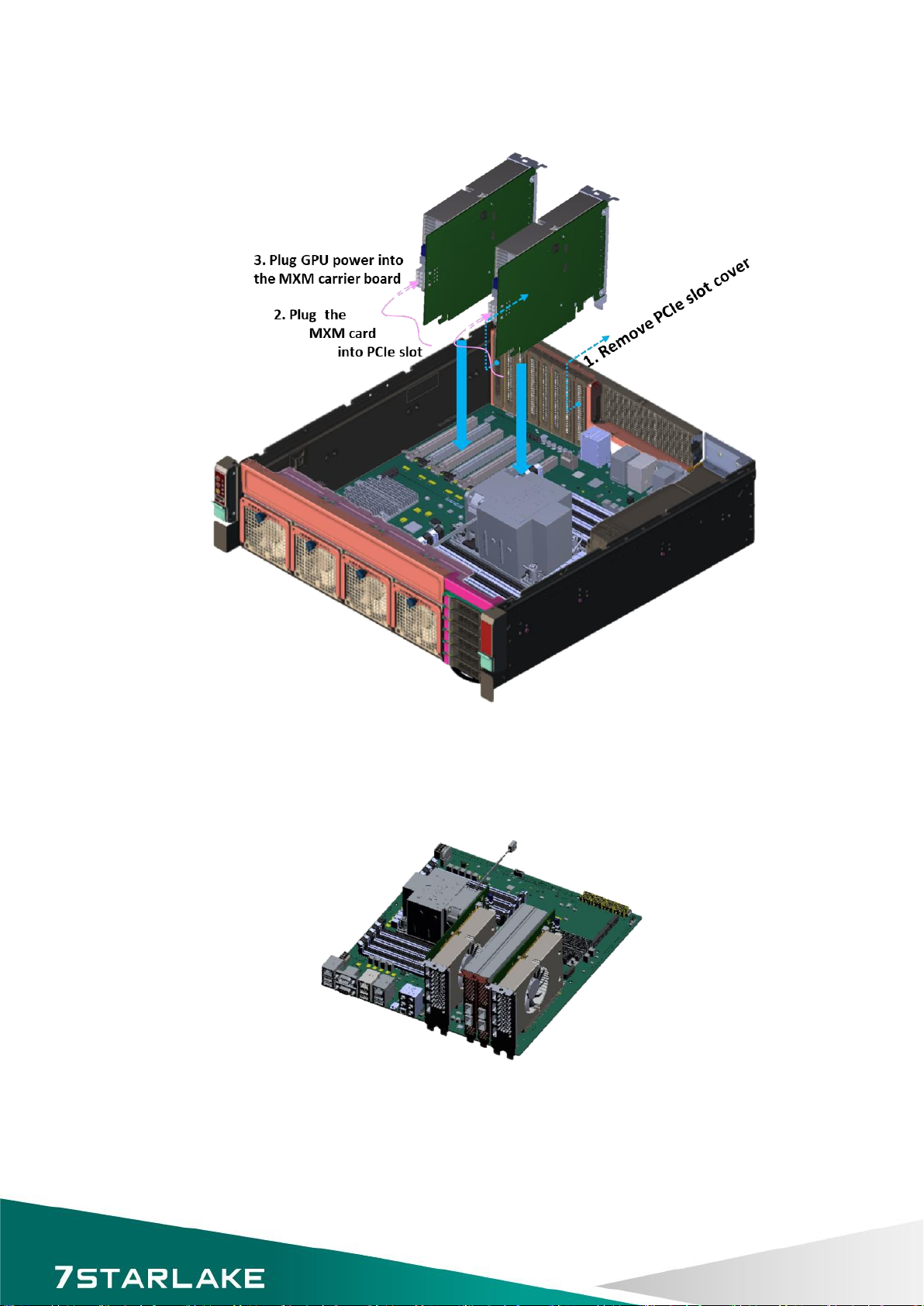
1.6 Installing the GPU Card...
1.6.1 Remove the PCIe slot cover
1.6.2 Plug the MXM carrier card with MXM GPU card into the PCIe slot1 (then 7 for 2nd MXM
card)
1.6.3 Plug GPU power into the MXM carrier board
✽
Suggest to install extra accelerated card at Slot 4 &5.
13
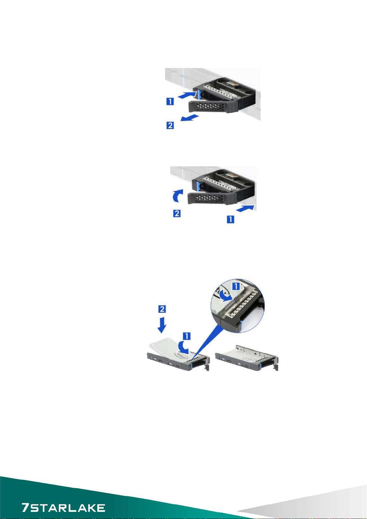
1.7 Installing Disk Drives...
1.7.1 Installing SSD in the Mobile SSD tray
Figure 2.5Removing the mobile SAS / SATA HDD trays
1. Press the tray button and release the lever as shown.
2. Pull the SSD assembly out of the drive bay.
1. With the open latch, insert the SSD assembly into the drive bay until the end of the SSD cage.
2. Push in the lever when it is secured with a click.
1.7.2 Installing the SSD
Figure 2.6 2.5”SSD installation (tool-less type)
1. Slide in the SSD until align the anchor points of SSD tray.
2. Push down the SSD when it is secured with a click.

14
1.8 PSU Installation and Removal...
1.8.1 CRPS module installation
1. Insert CRPS module into the PSU cage and push until it is secured into place.
1.8.2 CRPS module removal
1. Press the latch without release as shown.
2. Pull the module handle to remove it from the PSU cage.
1.9 Slide Rail or Pallet...
1. Attach the inner rail to the chassis base while aligning T-pins on the side of the system with the slots on the inner rail.
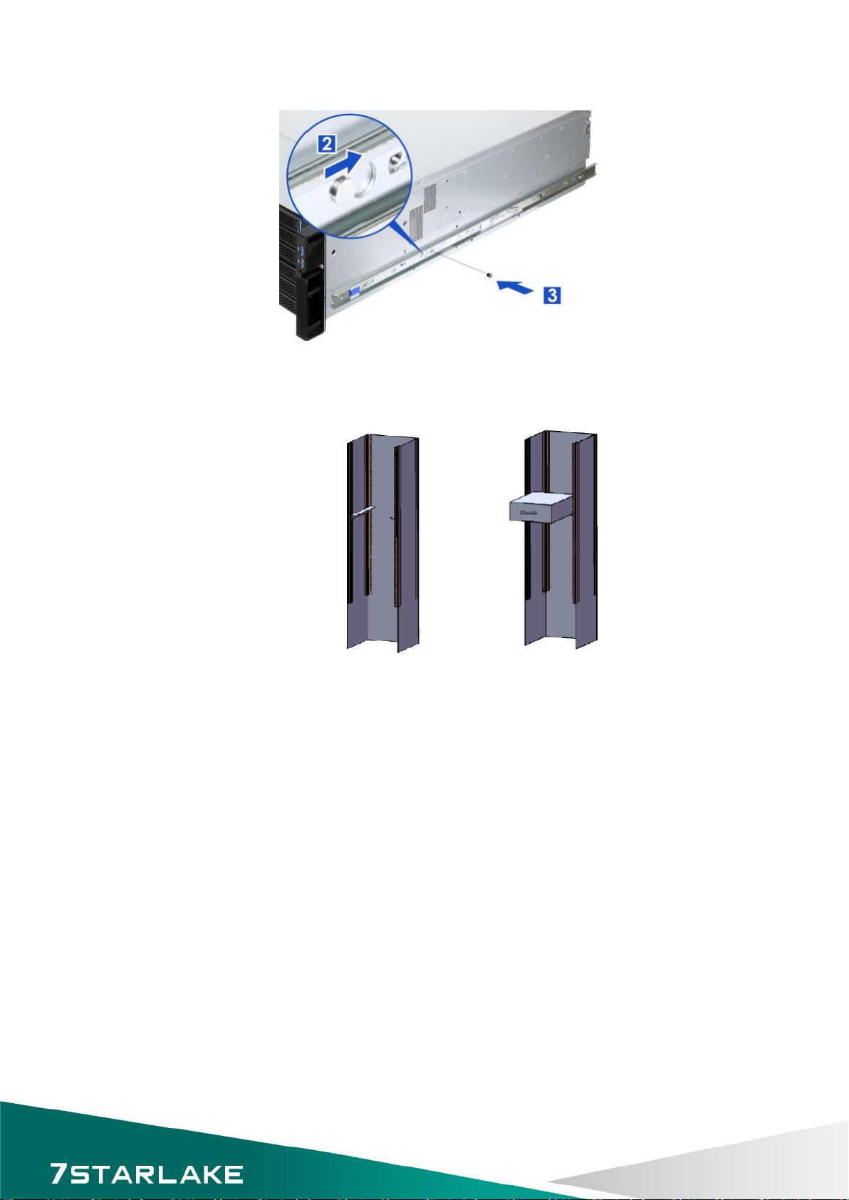
15
2. Engage T-pins with the slots on the inner rail as shown.
3. Secure the inner rail with one screw.
Install the chassis in the cabinet with the slide rail or pallet supplied /

16
2Chapter2 : Operation..
2.1 The Front Panel...
(Overview)
2.1.1 Switch, Buttons and I/O Interfaces.
2.1.2 LED indicators for System Status
2.1.3 LED Indicators for SSD Power & Status
2.2 The Rear Panel...

17
2.2.1 Plug the AC power with standard IEC power cable
2.2.2 Plug the cable into the I/O jack by the Device
2.2.3 Broke the cover to install function card into PCIe slot
2.3 Replacing the system Cooling Fan...

18
3Chapter 3 : Motherboard Overview
3.1 Motherboard Image…

19
3.2 Motherboard Layout…
✽
Notes:
CPU SLOT1/3/5/7 : PCIe 4.0 x16 Slots
* SLOT1 will be disabled when either M.2-C01 or M.2-C02 is in use.
* SLOT1 will change to PCIe x8 when M.2-C03 or/and M.2-C04 are in use.
* SLOT3/5/7 will change to PCIe x8 when SLOT2/4/6 is in use respectively.
CPU SLOT2/4/6 : PCIe 4.0 x16 Slots (PCIe 4.0 x8 link)

20
Notes:
•See Chapter 2 for detailed information on jumpers, I/O ports, and JF1 front panel connections.
•" " indicates the location of Pin 1.
•Jumpers/LED indicators not indicated are used for testing only.
•Use only the correct type of onboard CMOS battery as specified by the manufacturer. Do
not install the onboard battery upside down to avoid possible explosion.
Table of contents
Other Star Lake Server manuals


Popular Server manuals by other brands

Wahsega
Wahsega Carina Event Manager Installer's guide

ADLINK Technology
ADLINK Technology cPCIS-6130R Series user manual

Supermicro
Supermicro SUPERSERVER E102-9AP-L user manual

ViewSonic
ViewSonic SC-T35 user guide

Polycom
Polycom RSS 2000 Getting started guide

BITMAIN
BITMAIN ANTMINER T17+ installation guide

Fujitsu
Fujitsu PRIMERGY TX150 S5 Service supplement

AMX
AMX AXF-S AXCESS SERVER CARDFRAME (WITH AXC-S... reference guide

Fujitsu
Fujitsu SPARC Enterprise T2000 Getting started guide

HP
HP QUICKSPECS BL20P specification

Lenovo
Lenovo ThinkSystem SR635 Maintenance manual

IBM
IBM 866251Y - Netfinity 5500 M20 Hardware Maintenance Manual


