Stara TORNADO 600MD Technical reference manual

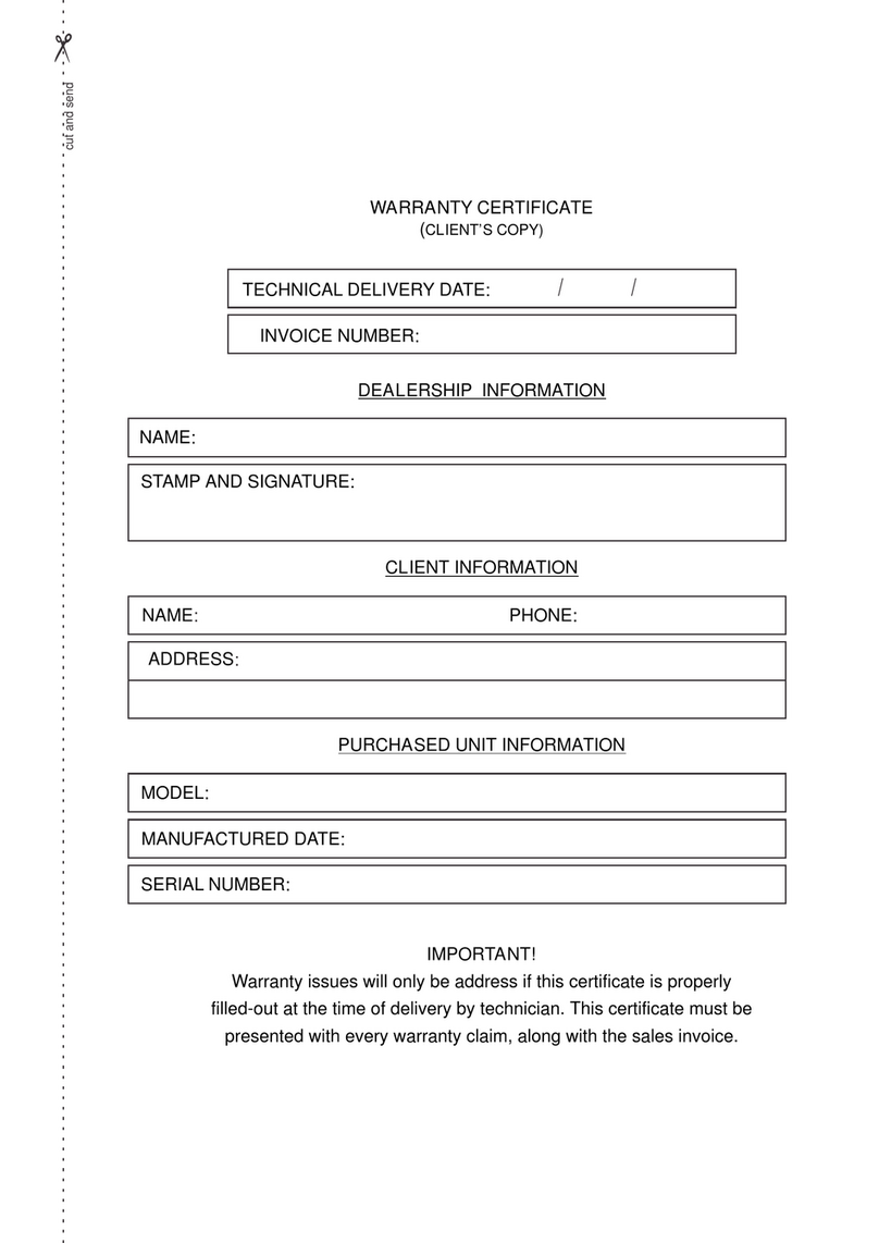
WARRANTY CERTIFICATE
(CLIENT’S COPY)
DEALERSHIP INFORMATION
CLIENT INFORMATION
PURCHASED UNIT INFORMATION
INVOICE NUMBER:
TECHNICAL DELIVERY DATE: / /
IMPORTANT!
Warranty issues will only be address if this certificate is properly
filled-out at the time of delivery by technician. This certificate must be
presented with every warranty claim, along with the sales invoice.
NAME:
NAME PHONE:
MODEL:
MANUFACTURED DATE:
SERIAL NUMBER:
STAMP AND SIGNATURE:
ADDRESS
:
:
cut and send


TECHNICAL DELIVERY TERMS
(this form must be completed by the technician and sent to stara)
CUSTOMER DATA
PURCHASED PRODUCT DATA
MODEL:
MANUFACTURED DATE
NAME: PHONE No.:
OPERATOR(S) NAME(S):
ADDRESS:
TECHNICIAN/DELIVERY AGENT:
INVOICE No.:
DELIVERY DATE / /
:
We declare that the implement referenced in this document, is being
delivered under normal conditions of use, as described and, with the
various adjustments and instructions.
CUSTOMER SIGNATURE TECHNICIAN OR DEALER’S SIGNATURE
ADDITIONAL INFORMATION
cut and send


Instructions for Warranty Claims
Technical Delivery
A) Stara, claims the right of a Technical Delivery to the original owner/purchaser of
the equipment, touching on the following items like: assembly, adjustments,
operations, maintenance and warranty.
B) The owner of the machine should designate one or more operators to be
trained.
C) It shall be up to the owner, that all instructions listed in the Operation and
Maintenance Manual be adhered to and be rigorously followed.
D) Maintain the equipment and all respective manuals in a perfect state of
conservation, and on a regular maintenance schedule, thus preserving the right to
warranty claims.
Warranty Terms
1) The warranty here expressed is the responsibility of the equipment dealership
along with the owner/purchaser of said equipment. Thus, it is understood, that
there is no direct dealings between the said owner/purchaser and the factory.
2) It is here defined that the first purchaser of the equipment is the DEALERSHIP,
and the second ownership will be here established as the CLIENT.
3) The following conditions are basic and will be that, the dealership will submit to
Stara's judgment all warranty claims.
Conditions of the Warranty
A) Stara guarantees its product “only to” the DEALERSHIP, and for the period of
six months, starting on the day of delivery to the CLIENT, along with the original
invoice and warranty certificate, which must be presented at the time of claim.
B) Stara restricts its responsibility strictly to the terms herewith contained in this
warranty, which will become non-transferable an will terminate automatically, in
case of the resale of the equipment by the second owner, the CLIENT or warranty
termination by the CLIENT.
C) The warranty covers exclusively material defects and/or of fabrication defects,
being that, labor, freight, and other expenditures are not covered by the Warranty,
for they are the responsibility of the DEALERSHIP.
D) Requested revisions by the CLIENT, even though the equipment is still under
warranty, will be subject to charges.

E) The warranty of parts and components which were replaced, will end herewith
the warranty of the equipment.
F) In cases of warranty service delays, those will not warrant the purchaser the
right to indemnity for damages, or extension of the warranty.
Items Excluded from the Warranty
Not included are such items as: hydraulic oils and lubricants, filters, greases and
the like,charges for roadside assistance or help, on-site assistance and any
equipment maintenance or help by Stara personnel; all these are the
responsibility of the purchaser.
Also not inclusive are: tires, inner tubes, electrical and electronic equipment,
batteries, engine, starter motor, alternator, fuel injection pump, these again are not
inclusive of Stara's warranty since they have specific manufacturer's warranty on
each of said components.
Other charges or expenses such as: transportation or travel expenses, towing
services, material damages or damages against the owner or his agents , these
are the sole responsibilities of the purchaser, until otherwise proven through the
results of investigations done by qualified and certified agents of the state or
government.

Warranty Forfeiture
The warranty will become null and void at such time as:
A) it is established that the defects or damages are the result of, inappropriate use
of the equipment, through the failure of not following instructions as specified on
the supplied manual, or the failure of untrained or inexperienced operators.
B) the product suffered repairs or modifications in repair shops which are not part
of Stara's authorized dealerships.
C) the parts or components present damages due to inappropriate use, or
damaged by other parts which are not genuine or original parts of the equipment,
by the end user.
D) the product suffers any type of misuse, even to the extent of causing safety
issues,concerns or breaches, and it will be per the company's judgment on such
matters, and it will carry the final word, until otherwise proven through the results of
investigations done by qualified and certified agents of the state or government.
E) the equipment is not up to date on all current revisions or upgrades, and/or if the
owner will not furnish solicited documentation.
F) the hydraulic system is contaminated by impurities of unauthorized or non-
recommended fluids.
G) the equipment is found to have damaged, scraped, illegible or no ID plate.
H) the warranty is found to have incomplete or erroneous information or any
unauthorized alterations.
I) the equipment was adversely misused in situations such as: working or was
driven at speeds which exceeded recommended speeds, overloading equipment
during work, etc.
Note: Any fabrication defects and/or material defects, the object of this warranty,
will not constitute, and under no hypothesis will it be a motive to rescind any
purchase or sales contracts/agreements, nor will it warrant the purchaser the right
to indemnity of any nature, save only those established by Consumer Rights or
Civil Codes; as specified in the country of purchase or sale.
TECHNICAL ASSISTANCE
Besides the instruction manual, the users of Stara products can call the nearest
authorized dealership to obtain any needed assistance. The dealership, by its
own merit, can seek information and assistance from the After-Sales Department
at Stara, whenever a difficult situation presents itself, or the need arises to resolve
any problems.

REPLACEMENT PARTS
Parts replacement should only be done using original parts from Stara, the
which , besides preserving the warranty rights as a consumer, will not
compromise the operation and the maintenance of the equipment.
PROJECT MODIFICATIONS
Stara S/A reserves the right to introduce project modifications of its
products for the end of its improvements or refinement, regardless of any
obligations to upgrade any previously manufactured equipment.
Stara S/A AgriculturaMachinery and Implements, Ind.
Não-Me-Toque, RS, Brazil

STARA S.A. - Agricultural Machinery and Implements Industry
AV. STARA, 519
Não-Me-Toque,RS - Brazil
CEP 99470-000
Phone/Fax:+55 54 3332-2800
e-mail: [email protected]
Home page:
Jan./2011 - Rev. 03
www.stara.com.br
INSTRUCTION AND
PARTS MANUAL
Constant Evolution
TORNADO 600MD
MONO DISC SPREADER


TABLE OF CONTENTS
INTRODUCTION
1 - ..................................................................................06
2 - .............................................................................06
3 - TECHNICAL SPECIFICATIONS...................................................................07
4 - SAFETY MEASURES...................................................................................07
5 - TORNADO 600MD ASSEMBLY....................................................................08
6 - MOUNTING AND ADJUSTMENTS...............................................................09
6.1 - Hooking-up Implement to Tractor...........................................................09
6.2 - Drive-shaft Mounting.............................................................................11
6.3 - Adjustment and Procedures..................................................................12
6.3.1 - Rate Adjustments..........................................................................12
6.3.2 - Product Placement Positioning.....................................................12
6.3.3 - Vane Adjustments.........................................................................14
6.3.4 - Overlapping Adjustment Between Runs........................................14
6.3.5 - Procedure for Final Coverage.......................................................15
6.3.6 - Procedure to Confirm Rates..........................................................16
7 - PRODUCT APPLICATION TABLES..............................................................17
3
7.1 - TABLE I - Potassium Chloride (00-00-60) 1120 kg/m ............................17
3
7.2 - TABLE II - Formulated NPK Fertilizer/in grain(05-20-30) 1030kgm .......18
3
7.3 - TABLE III - NPK Fertilizer Mixture (05-20-30) 990kg/m .........................18
3
7.4 - TABLE IV - Ammonia Sulfate1090kg/m ................................................19
3
7.5 - TABLE V - Triple Superphosphate(00-42-00) 1100kg/m .......................19
3
7.6 - TABLE VI - Urea (45-00-00) 765kg/m ...................................................20
3
7.7 -TABLE VII - Pre-germinated Rice/ 3 days (IRGA-409) 660kg/m .............20
3
7.8 - TABLE VIII - Dry Rice (IRGA-409) 600kg/m ..........................................21
3
7.9 - TABLE IX - Common White Oats 490kg/m ............................................21
3
7.10 - TABLE X - Dark Oats 540kg/m ............................................................22
3
7.11 - TABLE XI - Barley BR-2 710kg/m ........................................................22
3
7.12 -TABLE XII - Common Small Corn 844kg/m ..........................................23
3
7.13 - TABLE XIII - Wheat (CEP-27) 820kg/m ...............................................23
8 - ACESSORIES - USE AND ADJUSTMENTS.................................................24
8.1 - Conductors used in Row Distribution....................................................24
8.1.1 - Adjustment of the Tornado 600 MD to Fertilize in 2 rows................25
8.2 - Larger Agitador (Christmas Tree)..........................................................25
8.2.1 - Main Components.........................................................................26
8.3 - Protective Cap-f/Seeds(Chinese Cap)..................................................27
9 -
TORNADO 600MD............................................................................................28
10 - ..........................................................................................28
10.1 - Daily Maintenance..............................................................................28
10.2 - Periodic Maintenance.........................................................................29
...............................................................................................05
MAIN COMPONENTS
IDENTIFICATION PLATE.
PROBLEMS, POSSIBLE CAUSES AND/OR SOLUTIONS FOR THE
MAINTENANCE

TABLE OF CONTENTS
10.3 - Lubrification........................................................................................29
10.3.1 - Recommended Oils....................................................................29
10.3.2 - Recommended greases..............................................................30
10.3.3 - Special Precautions....................................................................30
10.3.4 - Storage.......................................................................................30
11 - ......................................................................................31
11.1 - ...........................................31
11.2 - .............................................32
11.3 - .......................................35
11.4 - ............................................................36
11.5 - .............................................37
11.6 - ..........................................................38
PARTS CATALOG
TORNADO 600 MD MAJOR ASSEMBLY
TORNADO 600 MD SUB-ASSEMBLIES
FASTENER PKG ASSY-TORNADO 600 MD
PROTECTIVE CAP-F/SEEDS
MIXER/CHRISTMAS-TREE PKG ASSY
DEFLECTOR PKG ASSY..........
5

INTRODUCTION
Dear Client,
The Centrifugal Mono-disc Spreader, model Tornado 600MD, was
developed to distribute through a casting process, fertilizers, corrective agents
and seeds in general, with uniformity and precision.
The distribution is done by a single disc, with 4 adjustable vanes, which
allows for different densities, granularity and work rows.
The Tornado 600MD is hooked-up to a tractor on the three point hydraulic
system, with pins of categories I and II, and activated by the PTO.
Using certain accessories, it is possible to row-spread and even apply
powdered products.
To use the equipment properly, it is important that this instruction manual is
read attentively, and keep it in pristine conditions for future usage and
consultations, should there arise questions and doubts.
STARA makes available to you exclusive call-ins to the After-Sales
Department, to better assist you and your dealer, so that you will optimize the
usage of your equipment.
NOTE: This manual is available on our site: along with
information on our complete line of products.
Stara S/A Agricultural Machinery and Implements, Ind.
Não-Me-Toque, RS, Brazil
www.stara.com.br,
6

7

2 - ID PLATE
The ID plate (Figure 02) shows the model no. of the machine, weight, serial
no., and also the date manufactured. This information is fundamental in the
traceability of the machine during its life cycle. The ID plate is placed on the
chassis of the implement.
1 - MAIN COMPONENTS
MOD.: PESO: kg
Nº
SÉRIE:
FAB.:
MÊS/ANO /
STARA S.A. IND. DE IMPLEMENTOS AGRÍCOLAS
NÃO-ME-TOQUE - RS BRASIL
Figure 02
1 - Chassis
2 - Reservoir
3 - Gear Box
4 - Drive-shaft
5 - Disc
6 - Vanes
7 - Agitators
Figure 01
1
2
3
4
5
6
7
8

3 - TECHNICAL SPECIFICATIONS
- Maximum capacity of trailer............................ 600 liters or 700 kg
- Empty weight.................................................140kg
- Height............................................................127cm
-Width .............................................................143cm
-Working width................................................. 4 to 22m
- Flow range - Seeds........................................ 2.5 to 420 kg/ha
- Granular fertilizer............... 30 to 1000 kg/ha
-Dry powdered fertilizer ....... 300 to 5000 kg/ha
- PTO revolutions............................................. 540 rpm
- Hook-up pins Categories ............................... I and II
- Hook-up system............................................. 3 points
- Lubrication points .......................................... 2
4 - SAFETY MEASURES
The Tornado 600MD is a simple implement which does not pose high risks
to the operator, still it is important to observe certain safety measures, such as:
a) When hitching the implement, remember to place the locking pins on the 3-
point hitches;
b) Confirm the drive-shaft length before hooking it up (see item “Mounting the
drive-shaft” page 11);
c) Only hookup the PTO when the tractor is turned off;
d) Do not stand near the drive-shaft while it is in motion ;
e) Never turn off the engine with the PTO turned on;
f) Avoid allowing joy-riders or hitch-hikers on-board while the operator is
working;
g) Check your surroundings before maneuvering the tractor or the implement,
to avoid injury to personnel, animals or obstacles;
h) Do not turn-off the PTO with the slide-gate open;
i) Do not turn-on the PTO with the implement stationary;
j) Do not allow personnel to remain in the area of the product distribution;
k) Remain alert, making sure that there are no foreign objects mixed-in with the
product to be distributed.
9

5 -TORNADO 600MD ASSEMBLY
To lessen the implement’s transportation volume, the reservoir and the
portal opening lever leave the factory disassembled from the chassis, and will be
mounted in the field. The reservoir is mounted to the chassis using 3 reinforced
plates, which can be easily removed for cleaning.
To proceed with the assembly, mount the 3 plates to the reservoir using 14
screws onto the pre-existing drilled holes(Figure 03), make sure that the screw
heads are inside the reservoir.
Figure 03
10

6 - HOOK-UP, ADJUSTMENTS AND PROCEDURES
ATTENTION! Before hooking-up and operating the implement follow these
procedures :
- Verify that the inside of the reservoir is clean of all foreign objects. Remove it,
should you find any foreign objects.
- Remove the transmission main oil plug and replace it with a breather, as
shown (Figure 04).
- To check the gear box oil level, place the implement on a level surface and
remove the rear end plug (Figure 04).
6.1 - Hooking-up the Implement to the Tractor
The Tornado 600MD, in principal, can mount on any tractor possessing a
hydraulic lift.
To hook-up the spreader to the tractor, follow these steps:
1st) Dis-arm the tractor traction bar and move it to the side, or remove it
completely, leaving room for the drive-shaft.
2nd) Hook-up the implement onto to the 3-points of the tractor hydraulic
system. The mounting pins of the Tornado 600MD where made for two types of
categories I and II (Figure 05).
ATTENTION! It is important that the arms of the 3rd point and of the two
side braces (Figure 06), should be adjusted with the maximum slackness of 5 cm,
so that these items will not interfere with the tractor’s tires.
3rd) Level the implement in relation to the terrain. Checking all sides so that the
implement is leveled (Figures 07 and 08), also verify that the distance of the disc to
the ground should be 75 cm (Figure 08).
Figure 04
Replace the Main Oil Plug
with a Breather.
Rear End Plug
(check oil level)
11

Cat. I = Ø 22
Cat. II = Ø 28
Figure 05
Figure 07 Figure 08
Figure 06
75cm
max. 5 cm
3
12

6.2 - Drive-Shaft Mounting
Raise the implement until the drive-shaft reaches the same height of the
tractor’s PTO (Figure 08).
Place half of the drive-shaft on the side of the implement, and the other half
of the PTO, placing them side-by-side, to adjust their length.
If the drive-shaft is too long, cut the tube to the same length (Figure 09).
The two tubes (male and female), should have the minimum gap of 25mm
on either side (Figure 09).
Avoid over-cutting the tubes, thus maintaining an area of engagement
between the male and female, in case of maximum drive-shaft span, or be it, when
the implement is elevated to major heights.
Remove dirt and grease of the thinner tube’s external side.
o
ATENTION! The drive-shaft angle should never exceed 30 , when in the
working position (Figure 10).
Figure 10
0
max. 30
Figure 09
Min.
25 mm
Min.
25 mm
13
Table of contents
Other Stara Spreader manuals
Popular Spreader manuals by other brands
Agri-Fab
Agri-Fab Agri-Fab 45-03153 owner's manual
Roto-Spread
Roto-Spread 532-16 Operation and parts manual

Trynex
Trynex SnowEx V-MAXX SP-2400 H Owner's/operator's manual

Millcreek
Millcreek 27+ Operator's manual

MTD Pro
MTD Pro HWSS 100 Assembling instructions
LEHNER
LEHNER AgroDos Operating instructions with parts list
