Neilsen CT2214 User manual

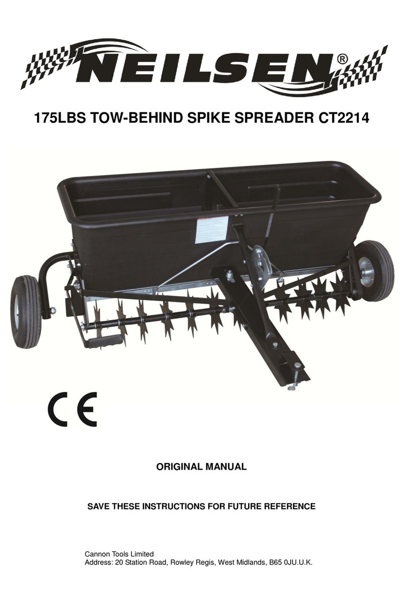
175LB TOW-BEHIND SPIKE SPREADER CT2214
INSTRUCTION MANUAL
SAVE THESE INSTRUCTIONS AND PRECAUTIONS.
READ ALL PRECAUTONS AND INSTRUCTIONS BEFORE USE.
Cannon Tools Limited
Address: 20 Station Road, Rowley Regis, West Midlands, B65 0JU.U.K.

1

1
EC DECLARATION OF CONFORMITY
We CANNON TOOLS LTD
20 Station road, Rowley Regis, West Midlands,B65 0JU.U.K.
Declare that the following machine complies with the appropriate basic safety
and health requirements of the EC Directive based on its design and type, as
brought into circulation by us.
In case of alteration of the machine, not agreed upon by us, this declaration will
lose its validity.
Product description:175LB TOW-BEHIND SPIKE SPREADER
Model: CT2214
Applicable EC Directives:
EC Machinery Directive 2006/42/EC
Harmonized standards
EN ISO 12100:2010, EN 349:1993+A1:2008,
EN ISO 14120:2015, EN ISO 13857:2008
20 Station Road, Rowley Regis, West Midlands, B65 0JU.U.K.
Mr. Gurcharan Tony Singh Sanghera
Managing Director
CANNON TOOLS LTD
sign
Gurcharan Tony Singh Sanghera
2021-07-06

2
1. SPECIFICATIONS
Capacity: 175LB
Spread Width: 4"/1M
Pneumatic Tyre: 10"
Coverage: 40000 Sq/ft
Spikes: 12 spike wheels, 7" dia.
Adjustable flow control lever with stop feature.
Works with lawn/garden tractors and ATVs.
2. GENERAL SAFETY INSTRUCTIONS
Warning: When using tool, basic safety precautions should always be followed to
reduce the risk of personal injury and damage to equipment. Read all instructions
before using this tool!
STAY ALERT. Do not operate the machine while under the influence of drugs,
alcohol, or any medication that could affect your ability to use it properly. Do not
use this machine when you are tired or distracted from the job at hand. Be aware
of what you are doing at all times. Use common sense.
USERS. Do not at any time carry passengers sit or stand on the machine. Do not
allow children to play on, stand upon or climb in the machine. Never allow
children or people unfamiliar with these instructions to use the machine.
Local regulations can restrict the age of the operator.
AVOID DANGEROUS CONDITIONS. Make sure there is adequate surrounding
workspace. Cluttered areas invite injuries. Keep your work area clean with
sufficient light. Keep the area around the machine clear of obstructions, grease,
oil, rubbish & other debris which could cause persons to fall onto moving
parts.
KEEP BYSTANDERS AND CHILDREN AWAY. Keep unauthorised persons a
safe distance away from the machine. If approached, stop the machine
immediately. Do not allow children to handle, climb on or use the machine. Keep

3
in mind the operator or user is responsible for accidents or hazards occurring to
other people or their property.
INSPECT YOUR MACHINE. Check all bolts, nuts & screws for tightness before
each use, especially those securing guards & drive mechanisms. Vibration
during use, may cause these to loosen. Replace damaged, missing or
failed parts before using. Warning labels carry important information. Replace
any missing or damaged warning labels.
DRESS PROPERLY. Do not wear loose clothing, gloves, scarfs, neckties
or jewellery (rings, wrist watches), which can be caught in moving parts.Always
wear long trousers. Always wear substantial non slip, substantial or heavy-duty
safety footwear are highly recommended when working. Never operate barefoot
or when wearing sandals. Wear a face or dust mask if the operation is dusty.
Always wear safety glasses/goggles and/or face shields. Everyday eyeglasses
have only impact resistant lenses; they are not safety glasses/goggles. Wear
protective hair covering to contain long hair, preventing it from getting caught in
machinery.
DO NOT OVERREACH. Keep proper footing and balance at all times
when using the machine. Never stand on the machine. Serious injury could occur
if the machine is tipped or if the moving parts are unintentionally contacted. Do
not store anything above or near the machine, where anyone might stand on the
machine to reach them.
AVOID INJURY FROM UNEXPECTED ACCIDENT. Keep hands & feet out of the
way of all moving parts. Do not place any part of your body or any tool e.g. in
moving parts of the machine during operation.
DO NOT FORCE TOOL. Always work within the rated capacity. Do not operate
for a purpose for which it was not intended. Before operating vehicle on any
grade (hill) refer to the safety rules in the vehicle owner’s manual concerning
safe operation on slopes. Stay off steep slopes! Always operate at reduce speed
in rough terrain, along creeks, ditches and on hillsides. Do not operate close to
creeks, ditches and public highways. To avoid personal injury and/or equipment
damage DO NOT EXCEED 5 MPH. Always use caution when loading and
unloading the cart.

4
Only tow with recommended vehicles (Lawn/Garden Tractors and ATVs). Always
secure and lock dump cart to the vehicle hitch before operating.
This equipment is not designed to be used with zero-turn mowers.
NEVER LEAVE MACHINE RUNNING UNATTENDED. Do not leave the
machine unattended until it has come to a complete stop.
TYRE INFLATION. WARNING! Over-inflated tyres can explode and cause
serious injury. Avoid injury by NEVER over inflating tyres beyond the maximum
pressure printed on the side of the tyre wall. ALWAYS use FOOT or HAND pump
inflation devices.
INSPECT. Before using, always visually inspect to see that the tools are not worn
or damaged. Replace worn or damaged elements and bolts in sets, to preserve
balance. Always secure and lock aerator spreader to the vehicle hitch before
operating.
CRUSH AND CUT HAZARDS. Always keep hands and feet clear from moving
parts while operating the equipment. Always clear and keep work area clean
when operating. Always wear safety gear, eye protection, gloves and work
boots when operating the aerator spreader.
MAINTAIN YOUR MACHINE WITH CARE. Clean the machine immediately after
use. Keep the machine clean to ensure it operates to its full & safest
performance. When maintaining this machine, only the manufacturer’s original
replacement parts should be used.
PROTECT THE ENVIRONMENT. Take left over materials to an authorised
collection point or follow the stipulations in the country where the machine is
used. Do not discharge into drains, soil or water.
STORE IDLE EQUIPMENT. When not in use, the machine should be stored in a
dry location. Keep the machine away from children and others not qualified to
use it.

5
3. CONTROLS AND FEATURES IDENTIFICATION
Read this owner’s manual before operating the equipment. Familiarize yourself
with the location and function of the controls and features. Save this manual for
future reference.
1) Flows Control Lever – Controls the flow of material.
2) Poly Hopper – Do not exceed maximum load capacity 175lb.
3) Tires / Wheel – Do not exceed the recommended rate 25 PSI.
4) Aerator Spikes – Puts small holes in the ground.
5) Hitch – Pin-type design use only with approve vehicles.
6) Spike Control Handle – Lifts and lowers the aerator spikes.
1
3
2
6
5
4

6
4. ASSEMBLY
1. READ THE INSTRUCTIONS BEFORE ASSEMBLY
Read the towing vehicle owners manual and towing vehicle safety rules.
Know how to operate your tractor before using the tow-behind spreader.
Wear eye and hand protection when handling and when applying lawn or
garden chemicals.
Never operate tractor and spreader attachment without wearing substantial
footwear, and do not allow anyone to ride or sit on spreader attachment frame.
Never allow children to operate the tractor or spreader attachment, and do
not allow adults to operate without proper instructions.
Always begin with the transmission in first (low) gear and with the engine at
low speed, and gradually increase speed as conditions permit.
When towing spreader do not drive too close to a creek or ditch and be alert
for holes and other hazards which could cause you to loose control of the
spreader and tractor.
Before operating vehicle on any grade (hill) refer to the safety rules in the
vehicle owner’s manual concerning safe operation on slopes. Stay off steep
slopes!
2. Take all parts out of the shipping crate and inspect components to ensure
there are no missing pieces before starting to assemble the aerator spreader
follow steps 1 through 8.
TOOLS REQUIRED
Rubber or Wooden Hammer
10, 13, 14, 22 & 24mm Wrenches
Adjustable Wrench
Pliers

7
3. ASSEMBLY
STEP 1: Attach Tow Bar Assembly to the Hopper
1. Remove the two M6 lock nuts in the bottom front of the hopper (Pic.1).
2. Put a M14 hex nut and Ø14 big washer to the support strut of the fluted disc
assembly, then attach the support strut to the card slot of the tow bar, and tighten
with a Ø14 big washer and M14 hex nut. (Pic.1).
3. Insert the original bolts through the holes on the beveled side of the tow bar
assembly. Secure using the M6 lock nuts (Pic.2).

8
STEP 2: Attach Handle Assembly to the Hopper
1. Remove one M6 lock nut from the front top of the hopper (Pic.3).
2. Insert the original bolt through the holes on the adjustable handle assembly.
Loosely secure using a M6 lock nut.
3. Insert one M6x16 hex bolt with an Ø6 big washer through the other hole at the
top of the hopper and the adjustable handle assembly.
4. Loosely tighten the parts together using the M6 lock nut (Pic.4).

9
STEP 3: Assemble the Tow Bar and Adjustable Handle Together
1. Remove the M8x25 hex bolt and M8 lock nut on the tow bar assembly (Pic.5)
2. Insert the M8x25 hex bolt through the hole at the bottom of the adjustable
handle assembly and the tow bar assembly.
3. Secure together using a M8 lock nut (Pic.6).
4. Put the adjustable handle assembly in a suitable position and tighten all
hardware in the prior steps 2 and 3.
STEP 4: Attach Hitch Studs and Support
1.Remove the hitch studs at one of end of the hitch rod (Pic.7).
2.Insert the hitch rod through the hole at the bottom of the adjustable handle and
screw on the hitch studs (Pic.8).

10
3. Insert tow hitch studs at each end of the hitch rod and through hitch support
hole (left and right) at the bottom of the hopper. Secure using M6 lock nut
(Pics.9&10).
NOTE: Hitch studs should not be screwed too tight, they need to be able to rotate freely.
STEP 5: Attach the Control Handle
1. Remove the M6 lock nut on the upper left of the hopper (Pic.11)
2. Insert the original bolts through the support rod, wheel assembly bracket and
control handle and loosely secure together using a M6 lock nut.
3. Insert the M6x16 hex bolt through the hole on the hitch plate and hole on the
support rod and loosely secure using a M6 lock nut.
4. Use a M8x20 hex bolt to attach the control handle and wheel assembly
bracket together and loosely tight with a M8 lock nut (Pics.11&12).

11
STEP 6: Attach & Adjust the Tow Bar and Support Rod
1. Insert two M6x16 hex bolts through the holes on the support rod and the tow
bar and loosely tighten using two M6 lock nuts (Pic.13&14).
2. Put in position the tow bar and support rod and tighten all hardware in steps 5
and 6.
STEP 7: Attach the Wheels
1. Attach the wheels on the wheel brackets and secure using M16 lock nuts
(Pics15&16).

12
STEP 8: Final Adjustment and Assembly
1. Securely tighten all hardware in steps 1 through 7 before operating the spike
aerator spreader.

13
5. OPERATION
WARNING! Before operating or using this equipment, review the instructions below and safety
information. Failure to follow these instructions may result in property damage or injury to the
operator or bystanders.
IMPORTANT: Aerating is putting small holes in the soil up to 2.5 inches in length to create a
small reservoir that will bring oxygen, fertilizer and water down to the roots. For best aerating
results follow the soil/lawn preparation and operating aerator procedures.
SOIL AND LAWN PREPARATION
1. Remove large and small debris from work area.
2. If the ground is hard and dry, it is recommended the ground be sprinkled or
watered for one or two hours prior to aerating.
3. If the ground is wet or muddy DO NOT attempt to aerate or fertilize.
4. Mow lawn and remove loose clippings before aerating or fertilizing.
USING YOUR AERATOR SPREADER
1. DO NOT at any time carry passengers sit or stand on the aerator spreader.
2. Only tow with recommended vehicles (Lawn/Garden Tractors and ATVs).
3. Refer to the vehicle owner’s manual for proper safety and towing instructions.
4. Always secure and lock the aerator spreader to the vehicle hitch before
operating.
5. Determine the approximate square footage of the area to be covered and
estimate the amount of fertilizer or seed required. REFER TO MATERIAL
PACKAGING LABEL.
6. Move the aerator spreader to the area where application is to begin.
7. Loosen the plastic wing nut and move it to the desired setting. Retighten the
nut.
8. Making sure the flow control lever is in the “OFF” position; fill the hopper,
breaking up any lumps.
9. Lower the aerator spikes to the operating position.
10. Start the spreader in motion and then move the flow control lever to the “ON”
position as you travel across your lawn.
11. Do not make sharp turns with spikes in the ground.
12. On sloped lawns, always aerate in an up and down direction. DO NOT
attempt to aerate across the slope always go in an up and down direction.
13. Always use caution when backing the equipment to avoid “jack-knifing”.
Always back up in a straight line.
14. Raise aerator spikes to transport position when crossing over concrete or

14
other hard surfaces.
15. Do not aerate if the ground is extremely hard or dry. If ground is too dry,
sprinkle or water for one to two hours prior to use.
16. Do not aerate if the ground is too wet (muddy).
17. Vehicle braking and stability may be affected with the attachment of this
equipment.
18. Never exceed 5mph when towing the aerator spreader.
19. DO NOT exceed load capacity of 175lbs.
20. Always move the flow control lever to the “Off “ position to prevent
excessive release of fertilizer when stopping, turning or filling the aerator
spreader.
6. MAINTENANCE AND STORAGE
MAINTENANCE
● Rinse/dry inside and outside of the aerator spreader after each use.
● Before operating make sure the tires have the RECOMMENDED TIRE
PRESSURE.
●Regularly grease axle and wheel bearing area or when needed.
● Periodically check all fasteners for tightness.
● Annually clean and lightly lubricate spike assembly and shaft or when needed.
● Use a glossy enamel spray paint to touch up scratched or worn painted metal
surfaces.
● Spikes periodically need to be sharpened with a small grinder to maintain good
penetration.
● Never exceed load capacity rating of 175lbs it will damage the equipment..
IMPORTANT:
If a part needs replacement, only use parts that meet the manufacturer’s
specifications. Replacement parts that do not meet specifications may result in a
safety hazard or poor operations.
STORAGE
● Never allow material to be stored in the hopper for extended periods of time.
● Before storing make sure the aerator spreader is clean and dry for years of
trouble free service.
● Lightly lubricate all metal surfaces and moving parts to prevent rust.
● Store indoors or protected area during severe weather and winter months.

15
7. PARTS DRAWING

16
PARTS LIST
Part#
Description
QTY
Part#
Description
QTY
1
Cotter Pin Ø4x30
6
38
Support Rod
1
2
Flat Washer Ø20
6
39
Hex Bolt M6X35
1
3
Axle Spacer
2
40
Hex Bolt M6X45
1
4
Frame Left
1
41
Carriage Bolt M6X25
1
5
Hex Bolt M6X30
1
42
Teeth Washer Ø8
1
6
Short Bushing
2
43
Big Washer Ø6
19
7
Hex Bolt M5X10
16
44
Bushing
1
8
Scratch Board
4
45
Wing Nut M6
1
9
Middle Bushing
1
46
Nylon Washer
2
10
Handle Locking Plate
1
47
Adjustable Handle
1
11
Hex Bolt M6X16
22
48
Handle Grip
1
12
Mobile Door Assembly
1
49
Control Shelves
1
13
Hitch Studs
2
50
Support Shelves
1
14
Nylon Lock Nut M6
30
51
Gauge and Lever
Assembly
1
15
Flat Washer Ø16
14
52
Flat Washer Ø8
1
16
Fluted Disc Spacer
(Short)
2
53
Hex Bolt M6X20
2
17
Axle Spacer
16
54
Small Sprocket Axle
Assembly
1
18
Fluted Disc & Bushing
Assembly
4
55
Screw Bushing Ø22x18
1
19
Fluted Disc
8
56
Hex Bolt M5X35
2
20
Fluted Disc Spacer
(Long)
6
57
Flat Washer Ø5
2
21
Spring
1
58
Bushing Chain Cover
Spacer
2
22
Hitch Rod
1
59
Nylon Lock Nut M5
2
23
Hex Bolt M16X110
2
60
Bushing Chain Cover
1
24
Wheel Axle Hole Ø16
2
61
Bushing Chain
1
25
Hex Thin Nut M16
2
62
Big Sprocket Axle
Assembly
1
26
Wheel Assembly Bracket
1
63
Big Sprocket Spacer
1
27
Hex Bolt M8X20
2
64
Frame Right
1
28
Nylon Lock Nut M8
3
65
Hex Bolt M6X25
1
29
Nylon Lock Nut M16
2
66
Small Middle Support
1
30
Operating Handle
1
67
Middle Support
1

17
31
Support Rod
2
68
Hopper
1
32
Handle Grip
1
69
Hex Bushing
2
33
Tow-Bar Assembly
1
70
Support Strut
1
34
Hitch Bracket
1
71
Hex Nut M14
2
35
R Pin Ø3x75
1
72
Composite Bearing
1
36
Pin
1
73
Big Washer Ø14
2
37
Hex Bolt M8X25
1

18
CANNON TOOLS LTD
Add: 20 station road, Rowley Regis, west midlands,B65 0JU.U.K.
Made in China
Other manuals for CT2214
1
Table of contents
Other Neilsen Spreader manuals
Popular Spreader manuals by other brands

Buyers
Buyers SaltDogg PRO4000 installation instructions

Precision
Precision TBS4500PRCGY Assembly Instructions & Parts List

Texas
Texas DS 550 Mounting manual

SnowEx
SnowEx VX-3210 owner's manual

Black & Decker
Black & Decker 17182418 instruction manual

Art's-Way Manufacturing
Art's-Way Manufacturing X700 Operator's manual & parts list